What are carbide inserts?
Carbide inserts are tools used for precision machining of metals, including steel, stainless steel, cast iron, high-temperature alloys, and non-ferrous metals. They are interchangeable and come in different styles, grades and sizes.
There are a few basic considerations when choosing the right carbide inserts. One of these is the cutting operation, whether turning, milling or drilling. Carbide is more expensive per unit than other typical tool materials and is more brittle, making it susceptible to chipping and fracture. To overcome these problems, the carbide cutting tip itself is often shaped like a small plate for a larger tipped tool whose shank is made of a different material, usually carbon tool steel. This offers the advantage of using carbide at the cutting interface without the high cost and brittleness of making the entire tool from carbide. Most modern face mills use carbide inserts, as well as a variety of turning and end mills.
Inserts are used at high speeds, resulting in faster processing and ultimately improved finishing. Selecting the correct carbide insert is vital as it can cause damage to the cutting inserts, the machine and the cutting product.
Contour turning cutters TU RB 00223728.049-99.
For roughing and semi-finishing work. The fastening system for the cutting triangular plate is M (clamp).
| Designation | h = h 1 | b | f | L | Cutting inserts | Weight, kg | |
| Right | Left | ||||||
| К01.4931.000 MTJNR1616Н16 | К01.4931.000 -01 MTJNL1616Н16 | 16 | 16 | 20 | 100 | 01114-160308 TNUM-160308 | 0,255 |
| -02 MTJNR2016K16 | -03 MTJNL2016К16 | 20 | 125 | 0,375 | |||
| -04 MTJNR2020K16 | -05 MTJNL2020К16 | 20 | 20 | 25 | 0,405 | ||
| -06 MTJNR2520M16 | -07 MTJNL2520M16 | 25 | 150 | 01114-160408 TNUM-160408 | 0,610 | ||
| -08 MTJNR2525M16 | -09 MTJNL2525M16 | 25 | 25 | 32 | 0,830 | ||
| -10 MTJNR2525M22 | -11 MTJNL2525M22 | 25 | 01114-220408 TNUM-220408 | 0,840 | |||
| -12 MTJNR3225P16 | -13 MTJNL3225P16 | 32 | 170 | 01114-160408 TNUM-160408 | 1,130 | ||
| -14 MTJNR3225P22 | -15 MTJNL3232P22 | 32 | 01114-220408 TNUM-220408 | 1,140 | |||
| -16 MTJNR3232P22 | -17 MTJNL3232P22 | 32 | 32 | 40 | 1,490 | ||
| -18 MTJNR3232P27 | -19 MTJNL3232P27 | 32 | 01114-270612 TNUM-270612 | 1,485 | |||
| -20 MTJNR4032R22 | -21 MTJNR4032R22 | 40 | 200 | 01114-220408 TNUM-220408 | 2,210 | ||
| -22 MTJNR4032R27 | -23 MTJNL4032R27 | 40 | 01114-270612 TNUM-270612 | 2,185 |
The cutters in the basic version are supplied with a cutting plate produced by JSC KZTS, Kirovograd. * The grade of carbide, the number of cutting inserts and the manufacturer of the cutting inserts are specified when ordering.
| Designation | h = h 1 | b | f | L | Cutting inserts | Weight, kg | |
| Right | Left | ||||||
| K01.4932.000 MTNNR1616Н16 | K01.4932.000 -01 MTNNL1616Н16 | 16 | 16 | 9 | 100 | 01114-160308 TNUM-160308 | 0,225 |
| -02 MTNNR2016K16 | -03 MTNNL2016K16 | 20 | 125 | 0,335 | |||
| -04 MTNNR2020K16 | -05 MTNNL2020K16 | 20 | 10 | 0,365 | |||
| -06 MTNNR2520M22 | -07 MTNNL2520M22 | 25 | 150 | 01114-160408 TNUM-160408 | 0,520 | ||
| -08 MTNNR2525M16 | -09 MTNNL2525M16 | 25 | 12,5 | 0,760 | |||
| -10 MTNNR2525M22 | -11 MTNNL2525M22 | 01114-220408 TNUM-220408 | 0,770 | ||||
| -12 MTNNR3225P16 | -13 MTNNL3225P16 | 32 | 170 | 01114-160408 TNUM-160408 | 1,040 | ||
| -14 MTNNR3225P22 | -15 MTNNL3225P22 | 01114-220408 TNUM-220408 | 1,050 | ||||
| -16 MTNNR3232P22 | -17 MTNNL3232P22 | 32 | 16 | 1,370 | |||
| -18 MTNNR3232P27 | -19 MTNNL3232P27 | 01114-270612 TNUM-270612 | 1,365 | ||||
| -20 MTNNR4032R22 | -21 MTNNL4032R22 | 40 | 200 | 01114-220408 TNUM-220408 | 2.060 | ||
| -22 MTNNR4032R27 | -23 MTNNL4032R27 | 01114-270612 TNUM-270612 | 2.035 |
Cutters with a rhombic cutting insert f=55° for finishing contour turning. The cutting plate fastening system is P (lever).
| Designation | h = h 1 | b | f | L | Cutting inserts | Weight, kg | |
| Right | Left | ||||||
| K01.4976.000 PDJNR2020K15 | K01.4976.000-01 PDJNL2020K15 | 20 | 20 | 25 | 125 | 13124-150608 DNMM-150608 | 0,49 |
| -02 PDJNR2525M15 | -03 PDJNL2525M15 | 25 | 25 | 32 | 150 | 0,81 | |
| -04 PDJNR3225P15 | -05 PDJNL3225P15 | 32 | 170 | 1,36 | |||
| -06 PDJNR3232P15 | -07 PDJNL3232P15 | 32 | 40 | 1,55 | |||
| -08 PDJNR4032R15 | -09 PDJNL4032R15 | 40 | 200 | 2,23 | |||
| -10 PDJNR4040R15 | -11 PDJNL4040R15 | 40 | 50 | 2,83 |
What's good about carbide inserts?
Here are some of the reasons why carbide inserts are so good compared to other cutting tools:
- Carbide inserts are efficient and economical compared to other similar cutting tools.
- Some carbide inserts, such as tungsten, are highly durable and increase service life.
- Carbide inserts come in different shapes and grades that can be used in various applications.
- Carbide inserts provide much better surface quality than other tools.
Types and purpose of cutting tools
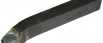
Prefabricated cutting tools can be divided into two main types. The first includes a cutting tool in which the holder and head are made of one piece of metal, and the cutting plate is a separate assembly element mounted at the end of the head. There are two main types of fastening, according to which cutters with mechanical and soldered fastening of plates are distinguished. The second type is a prefabricated cutting tool that has recently become widespread, in which a flat and long head with a cutting part is mechanically attached to a special mandrel that acts as a holder (see figure below). These cutters come with replaceable inserts of varying widths and thicknesses. In addition, some of them have adjustable head extension length.
In addition to normal and reinforced cutting tools of traditional design, there are a number of varieties for working in special conditions, including those that compensate for the shortcomings of low-power and non-rigid turning equipment. These include spring and inverted cutters, which are mainly used in home workshops and small industries. Spring cutters have an arched head and are designed for processing materials with an uneven and hard surface on small machines with a flexible structure. This head compensates for dynamic shocks and smoothes out vibration, which allows you to achieve the desired surface quality and protect the cutting insert from damage.
Inverted cutters became popular five or six years ago when a very easy to use and efficient cutting insert was developed.
Features and advantages of inverted cutting tools
The main advantage of this cutter is the facilitated removal of chips, since when the spindle rotates in reverse, it immediately goes down under its own weight. With this mode, the likelihood of clogging the groove with chips is sharply reduced, which is often the cause of jamming and tool breakage. Other advantages of this model include:
- ease of sharpening the blade;
- work at long reach;
- improved cooling mode (chips from below, coolant from above);
- long service life even with repeated sharpening of the plate.
In addition, its arbor has a precise height adjustment system, which eliminates the need to adjust the position of the tool using shims.
Manufacturing of carbide inserts
Let's take a look at the carbide insert manufacturing process to better understand its types and uses;
The right carbide insert for specific machining applications helps you stay ahead of the competition among cutting tool manufacturers.
Carbide inserts, mainly tungsten and cobalt, are supplied in powder form. The dry raw material is then mixed with a mixture of ethanol and water. The result is a gray slurry with the consistency of a yogurt drink. This mixture is dried and then sent to a laboratory for quality testing. This powder consists of agglomerates, small balls with a diameter of 20 to 200 microns, and is then transported to pressing machines where the inserts are made.
Carbide insert geometry
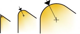
Carbide insert geometries can be divided into three main styles, optimized for several applications including roughing, finishing and medium cutting. Here are some diagrams that explain the working area of each geometry based on geometric chip breaking taking into account the depth of cut.
Roughing
Roughing involves a combination of high depth of cut and feed rate. This process requires maximum edge security.
Roughing
Finishing
Finishing involves watery depth of cut and low feed rates. This process requires low cutting forces.
Finishing
General processing
This operation includes a wide range of deep cut and feed speed combinations.
General processing
Features of using carbide inserts
Dimensions – in mm.
- Primary sharpening of the cutting edge is carried out at the manufacturer. Since it gradually wears out, the product simply turns over, that is, its other face, previously unused, becomes working. Therefore, there is no need to systematically sharpen the edge, which is typical for brazed turning tools.
- For rough processing of workpieces, thicker plates (up to 6) with long edges (up to 25) are used. Technological operations called finishing (for example, grinding) are performed with small products. Their minimum dimensions are: length – 7, thickness – 3.
Manufacturers of quality carbide inserts
Judging by the reviews of amateurs and professionals on thematic websites, there are no significant complaints about the products of the following manufacturers.
- Ceratizit (Luxembourg).
- Proxxon, BDS-Machinen (Germany).
- Ukrainian "Instrument-Service".
What to consider when choosing replacement nozzles
It is understood that they are purchased as a set, but without a cutter.
- Correspondence of linear parameters of tool and inserts.
- Specifics of product use. If metalworking involves removing significant layers from the workpiece, then you should select attachments whose material is inert to high temperatures. Working at high speeds is accompanied by increased vibrations. In this case, you need to pay attention to such characteristics of the samples as resistance to loads (mechanical).
- Type of parts processing. This already comes to the question of the required shape of the nozzles.
Entry Angle for Carbide Inserts
Leading angle KAPR (or leading angle PISR) is the angle between the cutting edge and the feed direction. It is important to select the correct approach/ascent angle for successful turning. The approach/lead angle affects:
- Chip formation
- Direction of cutting forces
- Cutting edge length in section
The role of geometry in plate production
When the role of geometry is discussed, people generally consider the macrogeometry and physical form of the carbides. Equally important here is microgeometry, which concerns the cutting edge of a microscopic shape.
Carbide insert geometry
Insert geometry is an important aspect as it affects the chip breaking pattern. Various shapes and angles provide optimal results in chip crushing depending on the material and application.
With the help of advanced technologies, the cutting surface of the plate is given a round, oval or any other geometric shape. Significant benefits in insert life and stability have been seen with the advent of new technologies. It is safe to say that future technological progress will stimulate further development in this field and even more significant achievements will be achieved.
Designation of turning inserts
The ISO designation for SMP consists of a combination of Latin letters and two-digit numbers, for example: CNMG 16 04 08 FN-43.
Let's write it like this:
1. The first letter of the designation symbolizes the shape of the plate, and it is the initial of the corresponding English word. For example, for plate shapes: R - round, S - square, T - triangular, etc. Table 7.1 shows the accepted designation for the SMP form.
Table 7.1 - Designation of the SMP form
| Form | Designation | |
| hexagonal | H | |
| octagonal | O | |
| pentagonal | P | |
| round | R | |
| square | S | |
| triangular | T | |
| rhombic | ε ,º | C |
| D | ||
| E | ||
| M | ||
| V | ||
| Continuation of Table 7.1 | ||
| rectangular | L | |
| parallelogram | ε,º | A |
| B | ||
| K | ||
| irregular triangular | W | |
| special | Z |
2. The second letter of the designation characterizes the size of the rear angle on the NSR. The need to encode this parameter is caused by the following circumstance. When cutting materials with different physical and mechanical properties, it is necessary to ensure optimal geometric parameters of the cutting part, including the value of the clearance angle on the SMP, which are given in Table 7.2.
Table 7.2 - Designation of the rear angle on the NSR
| The value of the rear angle on the NSR α,º | Special design | |||||||||
| Designation | A | B | C | D | E | F | G | N | P | O |
3. The third letter of the designation characterizes the degree of accuracy in manufacturing the SMP. Multi-blade tools require more precise MSPs than single-blade tools. In addition, more accurate SMPs on single-edged tools allow for unadjusted changes when they become dull.
The ISO standard provides 11 accuracy classes. The accuracy of SMP for turning is regulated mainly by three classes: G (high accuracy), M (medium accuracy) and U (normal accuracy). Table 7.3 shows the maximum deviations for the thickness s of the SMP and the diameter of the inscribed circle d, depending on the accuracy class.
Table 7.3 - Limit deviations of dimensions s and d for SMP forms H, O, P, R, S, T, C, E, V, W
| Accuracy class | Maximum deviations of dimensions, mm | |
| s | d | |
| G | ±0,13 | ±0,025 |
| M | ±0,05 — ±0,15 | |
| U | ±0,08 — ±0,25 |
Maximum deviations of size d for accuracy classes M and U depend on its nominal value.
4. The fourth letter of the designation characterizes the design features of the SMP, which mainly relate to elements for fastening the SMP to the tool body and the presence of chip-curling grooves. The ISO code letters indicating the design features of the SMP are given in Table 7.4.
Table 7.4 - Designation of design features of the SMP
| Designation of features | Schematic illustration | Design features |
| A | Without chip flutes and with hole | |
| G | With double-sided chip curling flutes and hole | |
| M | With one-sided chip-curling flutes and with hole | |
| N | Without chip curling grooves and holes | |
| R | With single-sided chip curling flutes, and without hole | |
| T | With one-sided chip-curling flutes and chamfered hole | |
| W | Without chip curling grooves, and a hole with a chamfer | |
| X | Special design |
5. The fifth character in the form of two numbers characterizing the size of the SMP along the length of the cutting edge, expressed only as an integer. Thus, a cutting edge length of 6.35 is designated as 06 (decimal places are discarded). Moreover, if the number is single-digit, then a zero is added in front of it. For a round-shaped SMP (R), its diameter is indicated. The designation of the length of the cutting edge depending on the shape of the SMP and the diameter of the inscribed circle d is presented in Table 7.5.
Table 7.5 - Designation of cutting edge length
| Diameter of inscribed circle d, mm | SMP form | |||||
| R | S | T | C | D | V | W |
| 5.560 | ||||||
| 6.350 | ||||||
| 9.525 | ||||||
| 12.700 | ||||||
| 15.875 | ||||||
| 19.050 | ||||||
| 25.400 |
6. The sixth character in the form of two numbers characterizes the thickness of the SMP. The principle of formation of this designation is the same as for the length of the cutting edge. The designation of the thickness of the SMP is presented in Table 7.6.
Table 7.6 — Designation of SMP thickness
| SMP thickness, mm | 1,59 | 1,98 | 2,38 | 3,18 | 3,97 | 4,76 | 5,56 | 6,35 | 7,94 | 9,52 | 12,7 |
| Designation | T1 | T3 |
7. The seventh symbol in the form of two numbers characterizes the radius at the top of the SMP. These numbers indicate how many tenths of a millimeter a given radius has. For example, a radius of 0.4 mm is designated 04, a radius of 1.6 mm is designated 16, etc. For round plates, place two zeros in this place. Standard radius values and their designations are given in Table 7.7.
Table 7.7 - Designation of the radius at the top of the SMP
| Radius r, mm | 0,2 | 0,4 | 0,8 | 1,2 | 1,6 | 2,4 | 3,2 | 4,0 |
| Designation |
8. The eighth letter character carries information about the design of the cutting edge. The definition of the designation is given in Table 7.8.
Table 7.8 - Designation of cutting edge design
| Designation | Sketch | Cutting edge design |
| F | Sharp edges | |
| E | Rounded edges | |
| T | Chamfered edges | |
| S | Edges with chamfer and rounding |
Sharp cutting edges F are designed for finishing. Executions E, T, S strengthen the cutting edge and are intended for roughing.
9. The ninth letter character characterizes the feed direction with which the SMP installed in the cutting holder can work. The explanation of the feed direction designation is given in Table 7.9.
Table 7.9 - Designation of feed direction
| Designation | Sketch | Feed direction |
| R | Right | |
| L | Left | |
| N | Right and left |
10. The tenth point of the SMP code is intended for special manufacturer designations. As a rule, this is information about the chip-breaking geometry of the front surface of the SMP. The ISO standard does not regulate this designation item, and it can be alphabetic, numeric, alphanumeric (maximum three characters possible).
Figure 41 – chip breaking geometry
In the course work, it is mandatory for turning inserts to indicate the shape of the front surface of the insert - the chip-breaking geometry, which is given in the directories-catalogs of manufacturers. For example, for semi-finish machining of carbon, alloy, low-carbon and stainless steels, the rake shape shown in Figure 42 is recommended.
Figure 42 - Front surface shape
Types of Carbide Inserts
Depending on the shape and material, several different types of carbide inserts are used for different purposes. These inserts are replacement attachments for cutting tools that typically consist of the cutting edge itself.
The inserts have different geometric shapes. For example:
Round plates
Round carbide inserts are used in grooving and milling machines.
Triangular or triangular inserts
Triangle or Trigon carbide inserts are triangular in shape with three equal sides and three 60 degree corners. These are triangular inserts that resemble a triangle but with modified shapes such as curved sides or mid-corners that include steps at the ends.
Four Sided Carbide Inserts
Four-sided inserts come in diamond, rhombic, square and rectangular shapes. Diamond-shaped inserts have a four-sided shape with two sharp corners for material removal.
Square shaped carbide inserts have four equal sides. On the other hand, rectangular plates have four sides. Two sides are longer than the other two. These types of carbide inserts are used for grooving applications where the short sides of the inserts have the actual cutting edge.
Diamond or parallelogram shaped carbide inserts also come in four-sided shapes, with an angle on the sides to provide cutting edge clearance.
Other shapes of carbide inserts include a pentagon with five equal sides and angles, while octagonal inserts have eight sides.
In addition to shape, carbide inserts also vary in angle. Here are some carbide inserts with different tip angles:
- Ball:
Ball cutter with inserts
The carbide insert for a ball cutter has a hemispherical ball tip, the radius of which is half the diameter of the cutter. This carbide insert can machine internal semicircles, grooves or radii.
- Radius cutter:
Radius cutter
The carbide insert for a radius cutter is a straight insert with a ground edge on the ends. This type of carbide insert is used on cutters.
- Chamfer cutter:
Chamfer cutter
A chamfer cutter has an angled section on the top to produce an angled cut or beveled edge on the workpiece.
Carbide inserts for difficult materials
The cutting tool industry has changed radically, and these changes can be seen in inserts for milling and turning complex materials.
In today's world, carbide, cermet, cubic boron nitride (CBN) and polycrystalline diamond (PCD) coated inserts play a vital role.
Inserts with unique geometry and coating withstand mechanical shock and heat, as well as abrasive wear. However, productive use of these inserts may require various external factors, one of which may be a partnership with a knowledgeable tooling supplier.
Carbide inserts are used in the production of various materials, such as steel alloys. These steel alloys become harder in many applications. This steel hardens to 63 RC and is commonly used in the dyeing and foundry industries.
Mold makers used to cut parts before heat treating, but now precision machining tools are used in a fully hardened state to avoid distortion during heat treatment. With this carbide insert technology, even fully hardened materials can be machined economically.
For example, aerospace machining uses carbide inserts. They used round carbide inserts when they wanted to machine hard steel. The profile thus provides a more reliable tool without vulnerable sharp corners.
Carbide Milling Inserts
Like other industries, carbide inserts are also used in the milling industry. They solve every imaginable application problem. These carbide inserts include ball head carbide inserts, high feed carbide inserts, toroidal head carbide inserts, reverse thrust carbide inserts and flat bottom carbide inserts. All of these carbide inserts solve specific problems in metal processing by means of turning and milling.
Most mold and die processing focuses on common mold materials in the milling industry. Only the geometry of the upper form differs from each other. Here are some mold materials that are preferred in the manufacturing industry:
Aluminum
Aluminum is the preferred material for milling shapes for some segments. These metal removal rates are eight to ten times faster than when machining steel.
Recently, aluminum manufacturers have developed higher quality, high-strength materials with hardness ratings ranging from 157 to 167 Brinell. Aluminum is difficult to machine on very smooth surfaces, so polishing becomes a critical operation in the final process.
Milling aluminum requires C2 inserts for roughing and C3 for finishing. Only general grade, medium grit carbide inserts with excellent wear resistance for roughing and finishing applications where sharp edges are required.
Turning cutters through passage.
Used for semi-finish and finishing turning. The plate fastening system is P (lever).
| Designation | h = h 1 | b | f | L | Cutting inserts | Weight, kg | |
| Right | Left | ||||||
| 2102-4036 PSSNR2525M12 | 2102-4036-01 PSSNL2525M12 | 25 | 25 | 32 | 158,3 | 03123-120412 SNMA-120412 | 0,96 |
| -02 PSSNR3225P15 | -03 PSSNL3225P15 | 32 | 180,2 | 03124-150612 SNMM-150612 | 1,08 |
| Designation | h = h 1 | b | f | L | Cutting inserts | Weight, kg | |
| Right | Left | ||||||
| 2102-4035 PCLNR2525M16 | 2102-4035-01 PCLNL2525M16 | 25 | 25 | 32 | 150 | 05124-160412 CNMM-160412 | 0,72 |
| -02 PCLNR3225P16 | -03 PCLNL3225P16 | 32 | 170 | 1,06 |
| Designation | h = h 1 | b | f | f1 | l | L | Cutting inserts | Weight, kg | |
| Right | Left | ||||||||
| 2109-4009 PTFNR2525M16 | 2109-4009-01 PTFNL2525M16 | 25 | 25 | 32 | 17,4 | 20,2 | 150 | 01124-160408 TNMM-160408 | 1,43 |
| -02 PTFNR2525M22 | -03 PTFNL2525M22 | 24,4 | 25,2 | 01124-220408 TNMM-220408 | 1,57 | ||||
| -04 PTFNR3225P22 | -05 PTFNL3225P22 | 32 | 170 | 2,75 |
Carbide inserts for sintered metals
Thanks to advances in technology, powder metallurgy produces extremely hard sintered metals for a variety of industries. For such industries, powdered nickel composite alloy is made by combining tungsten and titanium carbide to achieve a hardness of 53 to 60 RC.
For machining sintered metals, the choice of inserts depends on the material and workpiece. Carbide inserts with positive rake geometry can effectively cut thin-walled metal structures. However, thick-walled sintered metal parts require ceramic inserts with negative cutting edge geometry that provide a smooth, flat surface to the part.
Carbide particles and nickel alloy matrix reach up to 90 RC. When milling such materials, carbide inserts coated with various materials wear quickly along the flank surface with flat primary cutting edges. However, the superhard particles inside the insert create “micro-particles” that accelerate wear of the insert. It would be helpful if you were careful because sometimes carbide plates also break under the strong pressure of hard shock processing.
Carbide inserts have a high ability to cut hard metals containing tungsten and titanium.
Carbide inserts for top alloys
High-temperature resistant superalloys (HRSA) are widely used in the aerospace industry and are gaining acceptance in the medical, automotive, energy, and semiconductor industries. High-temperature superalloys such as Waspalloy and titanium 6Al4V are bonded to a titanium, magnesium and aluminum matrix, which generally pose processing challenges.
These alloys are super hard and require higher cutting zone temperatures in excess of 2000°F. When it comes to the carbide inserts used to cut these alloys, they are also super hard.
For machining high-temperature superalloys (HRSA), insert selection depends on the material and workpiece. Carbide inserts with positive rake geometry can effectively cut thin-walled high-temperature superalloys (HRSA). However, thick-walled alloy parts require ceramic inserts with negative cutting edge geometry to provide a smooth surface on the part.
Cost of carbide inserts
They are sold in sets, so the price depends on the configuration, shape, size and a number of other indicators. In addition, they may also include cutter bodies, which increases the cost. If we talk about its average value, then a kit without tools will cost 5,310 rubles, and with it – about 7,980.
In principle, it’s not that expensive, considering that, according to experts, the use of replaceable attachments gives a monthly saving of about 450 rubles on one lathe (with average equipment load).
Carbide inserts for turning
Turning ceramics is an almost flawless operation. This is typically a continuous machining process that allows a single insert to be cut for relatively long periods of time. This is an excellent tool for creating high temperatures to ensure optimal performance of ceramic plates.
On the other hand, milling can be compared to an intermittent turning mechanism. Each carbide insert on the tool body slides into and out of a slot as each cutter rotates. Compared to turning, hard milling requires a much higher spindle speed to achieve the same cutting speed for efficient operation.
To operate the cutting speed of a lathe on a three-inch diameter workpiece, a three-inch diameter three-flute cutter must operate at a minimum of four times the rotary speed. In the case of ceramics, the object generates a heat potential for each carbide insert. Therefore, when milling, each carbide insert must move faster to generate the thermal equivalent of a single-point turning tool.
Carbide Inserts for Threading
Carbide inserts are also used for thread cutting. High quality triangular carbide inserts can meet most of the needs of the threading industry. These carbide inserts are suitable for a wide range of applications, from basic to complex.
In the threading industry, carbide inserts have the following characteristics:
- Wide range of carbide insert grades and coatings to suit different materials and manufacturing processes.
- High-quality carving on inserts
- Possibility of cutting threads as small as 0.5 mm
- Inserts available for internal and external applications and for right and left hand threads
Meaning of Carbide Insert Markings
Typically, the model of carbide cutting inserts is represented by 10 numbers. In this model, the first four letters represent the characteristics of the lathe inserts, and the next six numbers represent the size and characteristics of the carbide cutter model.
DNMG150408-MS is a turning cutting insert. D represents the 55° diamond blade, N represents the blade clearance angle 0°, M represents the manufacturing precision degree of the blade, G represents the leading edge surface and center hole type, 15 represents the length of the cutting edge, the value is 15mm, 04 represents the thickness of the blade 4, 76 mm, and 08 represents the tool nose arc radius of 0.8 mm.
Types of carbide inserts - explanation of markings, designations, classification
Content:
- Grades of carbide inserts for turning
- An example of deciphering the markings of a turning plate
- Marking of threaded plates
- An example of deciphering the markings of a threaded plate
- Marking of carbide cutting and groove inserts
- Marking of milling inserts
- An example of decoding the markings of a milling plate
There is a huge variety of carbide inserts for turning and milling machines on the market today. Understanding the markings of plates, their types, shapes and sizes, even for a non-novice in turning, is not an easy task. In this article we will try to sort out all the carbide inserts, especially those presented in our online store.
Carbide inserts for specific tools
This characteristic is one of the simplest - the plates are placed on turning tools, drills or milling cutters, which means that this is the purpose we choose.
Turning plates are also easy to understand.
By purpose they are:
- Turning inserts
- Parting and grooving
- Threading Inserts
Turning inserts are selected for specific holders (cutters). You need to know such characteristics as the size and shape of the carbide insert, the grade of the insert, its radius, mode and type of turning (from roughing to finishing). Also, before purchasing replacement inserts, you need to decide what materials this alloy is suitable for processing. There are more universal alloys, and there are narrowly targeted plates.
How to understand the markings of carbide inserts
Grades of carbide inserts for turning
There are many standards and manufacturers, on average the plate markings are more or less the same (for example, according to ISO), there are slight variations among some brands. You need to “read” the insert from left to right; the name of the interchangeable tool says a lot - shape, angles, tolerances, length of the cutting edge, shape of the chipbreaker, etc.
The tables below provide explanations for the designation of turning plates .
As for chipbreakers, the Chinese company GESAC is constantly improving them. In 2022, new products appeared - LM and LR chipbreakers. You can read more about the new products in our Blog here.
Designations of the main GESAC chip breakers:
The letters and numbers after the chipbreaker designation indicate the type of alloy from which the tool is made. Here, each manufacturer has its own traditional designations.
An example of deciphering the markings of a turning plate
For clarity, let's decipher the turning insert CNMG090304-QF GP1115 from GESAC.
Let's look at the first four letters - CNMG . C – rhombus, N – clearance angle 0°, M – height tolerance limit +/- 0.08-+/- 0.18 mm; thickness +/- 0.13; the size of the inscribed circle is d +/- 0.05-+/- 0.13 and G indicates that the plate has a hole.
Let's go further - the numbers 090304 in the name of the plate “say” that the length of the cutting edge is 9.52 mm (09), the thickness of the plate is 3.18 mm (03) and the corner radius is 0.4 mm (04). The chipbreaker is at the insert in the example QF, which means that it is intended for finishing of steel and steel-based alloys. The most recent designation in the marking is alloy GP1115.
You can always seek advice from CNCMagazine managers to select the right tools for turning and milling machines. Write to us by E-mail: [email protected] cncmagazine. ru . Phone 8 (800) 555 4116.
Marking of threaded plates
The designation of replacement inserts for thread cutting is easy to understand. The major manufacturers of carbide inserts have more or less the same markings.
Below is a table to decipher the name of the threaded plate :
Threaded inserts are available for cutting internal and external threads, usually in right-handed or left-handed versions. An important characteristic of the tool is the thread profile. The CNCMagazine online store offers a tool with the following profile :
- ISO metric thread full profile
- Thread partial profile 60° and 55°
- Whitworth Pipe Thread
- British BSPT pipe thread for steam, gas and water pipes
- American Tapered Pipe Thread (NPT)
- American ABUT profile
- Trapezoidal thread 30°
- API thread (round)
- American UN thread, full profile
Each profile has its own standards, recommendations, and technical characteristics.
Let us take an example of the markings of a carbide insert for thread cutting.
An example of deciphering the markings of a threaded plate
Let's take a 16ER0.75ISO DM215 plate. 16 is the plate size (9.525 mm). ER in the marking indicates that the insert is intended for cutting external threads, right-handed. The following number - 0.75 means that the thread pitch is 0.75 mm. ISO - indicates that the thread standard is metric according to ISO. The last thing in the name is the alloy from which the tool is made.
Carbide insert codes often overlap between different manufacturers. Most often, only the names of the alloys used differ.
Marking of carbide cutting and groove inserts
brands of tools for cutting and grooving , as well as manufacturers. Different brands have their own markings. To quickly and easily decipher the purpose of the tool and find out its characteristics, look at the tables below.
Let's try to decipher the plate ZTFD0303-MG YBG202 . ZT means the tool is designed for grooving and turning, F means the insert is 3.0 wide, and D means it's a double-sided insert. 03 – cutting edge width is 3 mm, and apex radius is 0.3. M is the accuracy grade and G means the insert has a conventional chipbreaker. YBG202 is an alloy.
A breakdown of triangular-shaped cutting plates for processing straight and radius grooves from one Chinese brand is presented below.
Marking of milling inserts
Replaceable inserts for cutters come in trigonal (W), square (S), round (R), octagonal (O), rhombic 86° (M), rectangular 85° (A), pentagonal (P) and other shapes (Z). The shape of the cutter plate can be recognized by the first letter in the name. The second letter is the clearance angle of the insert, followed by the accuracy class, then the insert type. The first number after the letters in the name of the insert is the length of the cutting edge in mm.
Then comes the thickness of the plate, also in mm. You can tell the nose radius by the name of the milling insert.
As an example, let's look at the markings of milling inserts from the manufacturer SANDVIK.
An example of decoding the markings of a milling plate
APKT11T308-APM YB9320 cutters using this diagram
Insert shape – rectangular, relief angle 11°, accuracy class K, insert size 11, radius 0.8, alloy YB9320.
On our website, each product is described in detail, its characteristics, recommended types of processing, materials, etc. are indicated.
If you find it difficult to choose the right tool for metal turning and milling, we are always happy to help you.
We are waiting for your questions and requests for metalworking tools: by E-mail, by phone 8 or fill out the application below.
Online store
SEND YOUR APPLICATION