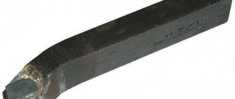
Turning cutters through persistent bent - a type of cutting turning tool used for processing cylindrical elements. Suitable for both preliminary and final processing.
They are used in private workshops, in workshops at machine-building plants, etc. Recommended for working with non-rigid objects. Produced in accordance with current GOST 18879-73.
Geometry characteristics
All modifications of turning cutters, persistent bent ones, consist of identical parts. Only the values of some angles change. The main working part is the head on the rod. The rod is attached to the tool holder. The front surface is sharpened at an angle that allows chips to escape.
The main cutting part is the main edge. Formed at the intersection of the main front and back sides. The turning cutter is complemented by an additional cutting edge.
The apex represents the intersection of the main and secondary cutting edges. The model range differs in angles. This is due to the specific purpose and specialization in different types of parts.
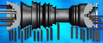
A wide range of sizes allows you to choose the best tool for the tasks coming to the workshop. Turning cutters, continuous bent, bent cutters of different sizes can have a rectangular or square cross-section.
Main dimensions and features of cutter geometry
| Height, mm | Width, mm | Length, mm |
| 16 | 10 | 110 |
| 20 | 12 | 120 |
| 25 | 16 | 140 |
| 25 | 20 | 170 |
| 32 | 25 | 170 |
| 40 | 25 | 200 |
| 40 | 32 | 240 |
| 40 | 40 | 240 |
| 50 | 40 | 240 |
| 50 | 50 | 240 |
The front surface is beveled to remove cutting products. The main cutting edge cuts metal. The apex is the intersection of the cutting edges. The angles of a turning cutter, or rather the sharpening of its tip, are determined by the type of work.
Advantages and disadvantages
The advantages of a continuous turning cutter include:
- long service life;
- high resistance to wear of the cutting part;
- processing of complex surfaces;
- high accuracy;
- reduced risk of discarding grinded objects.
For example, high-precision thrust cutters are used on small and stepped elements. The value of the main angle on the working part reaches 90°. Therefore, the level of operating vibration is reduced. There is less chance of accidentally spoiling or damaging the part.
A persistent turning cutter is a working tool designed to perform specific tasks. Manufactured in accordance with the requirements of the standard and correctly used for its intended purpose, it does not have any particular disadvantages. The defect is checked upon purchase.
Varieties and classification
In accordance with the current interstate standard, continuous turning cutters are produced in 2 types:
- straight lines with an angle of 90° (right and left);
- curved at an angle of 90° (right and left).
Straight through tools grind materials not only on lathes, but also on slotting and planing machines. There are two options:
- Steel made from high-speed steel (GOST 18868-73) - recommended for structures working with heated and non-alloyed parts.
- With a carbide tipped adjacent to a metal frame (GOST 18879-73) - designed for cutting dense metal.
A curved cutter is used as a cutting tool on turning machines. Designed for turning planes of stepped figures, shoulders, and cutting ends. Successfully grinds the outer sides of rotating bodies (cylindrical shafts, conical surfaces, etc.). In this type, two more groups are distinguished depending on the size of the rake angle:
- With an angle of 0° – steel and elements made of viscous materials are processed.
- With an angle of 10° - cast iron products and other fragile substances are processed.
There are finishing and roughing curved turning cutters, persistent ones.
Parts, elements and angles of a turning cutter
A turning cutter is one of the simplest and most common cutting tools, so we will consider the geometric parameters of the tool using its example.
Like cutting tools of all other types, the cutter consists of two parts: the working (blade) A and the fastening part B (Fig. 21.4). The fastening part serves to secure the cutter and has a square or rectangular cross-section.
The working part carries out cutting and consists of the following elements.
| to Fig. 21.4. Elements of a turning straight cutter |
The front surface A^ is the surface of the blade that comes into contact with the cut layer and chips during the cutting process. The back surface is the surface of the blade that comes into contact with the surfaces of the workpiece during the cutting process. There are main and auxiliary back surfaces. The main flank surface Aa is adjacent to the main cutting edge. The secondary flank surface A'a is adjacent to the secondary cutting edge.
Cutting edge - the edge of a tool blade formed by the intersection of its front and back surfaces. The part of the cutting edge that forms the larger side of the section of the cut layer is called the main cutting edge K, the smaller side of the section of the cut layer is called the auxiliary cutting edge K'.
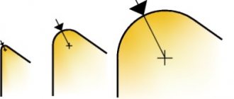
The tip of the blade is the area of the cutting edge where the two back surfaces intersect. For a pass-through turning cutter, the apex is the section of the blade at the intersection of the main and auxiliary cutting edges. The top can be sharp, rounded or in the form of a straight line.
The shape of a cutter blade is determined by the configuration and arrangement of its surfaces and cutting edges. The relative position of the front and rear surfaces and cutting edges in space determines the angles of the cutter. Angles are considered both on a stationary tool (static coordinate system) and during the cutting process, taking into account the trajectory of the points of the cutting blades (kinematic coordinate system). To manufacture and control the tool, an instrumental coordinate system is used.
Let's consider the cutter angles in statics, i.e. in a static coordinate system. To determine the cutter angles, the following coordinate planes are entered (Fig. 21.5).
The main plane Pv is a coordinate plane drawn through the point of interest on the cutting edge perpendicular to the direction of the speed of the main or resulting cutting movement at this point. The cutting plane Рп is a coordinate plane tangent to the cutting surface and passing through the main cutting edge of the cutter. The main cutting plane Рт is a coordinate plane perpendicular to the intersection of the main plane and the cutting plane. Working plane P„ is the plane in which the directions of the speeds of the cutting movement and the feed movement are located.
Rice. 21.5. Coordinates
planes TO determine the angles of the cutter P.
| Rice. 21.6. Turning angles |
| cutter in static |
Based on the conditions that the axis of the cutter is perpendicular to the line of the centers of the machine, and the top of the cutter is on this line, the turning cutter has main and auxiliary angles (Fig. 21.6).
The front angle y is measured in the main cutting plane Рт between the front surface A1 and the main plane Р„. It has a great influence on the cutting process. As y increases, the work spent on the cutting process decreases, the conditions for chip flow improve and the quality of the machined surface increases. But an increase in the rake angle leads to a decrease in the strength of the cutter and accelerated wear due to chipping of the cutting edge and a decrease in heat dissipation. There are positive (+y), negative (-y) and zero angles. When processing hard and brittle materials, small rake angles are used; for soft and viscous materials, the angles are increased. When processing hardened steels with carbide tools or during intermittent cutting, negative y angles are prescribed to increase the strength of the blade. Depending on the mechanical properties of the material being processed, the tool material and cutting modes, the angles y are assigned from -10° to +20°.
The clearance angle a is measured in the main cutting plane Pt between the rear surface Aa and the cutting plane Pp. Angle a is designed to reduce friction between the main flank face and the cutting surface. The elastic properties of the material being processed play a major role in assigning this angle. An increase in angle a leads to a decrease in the strength of the cutter. When processing viscous materials, large angles a are assigned, and when processing hard and brittle materials or with a large cross-section of the cut layer, smaller angles a are assigned. Angle a can be within 6... 12°.
The main entering angle<р is the angle between the cutting plane Рп and the working plane Ps. It has a significant effect on the roughness of the machined surface and the duration of the cutter before dulling. As the angle ср decreases, the deformation of the workpiece and the extraction of the cutter increase, vibrations appear, and the quality of the machined surface deteriorates. Most often, the angle φ for turning cutters is taken equal to 45°, but depending on specific conditions (primarily the rigidity of the part), it can decrease to 30° or increase to 90° (when processing long and thin shafts).
Auxiliary angle in plan (pj - the angle between the projection of the auxiliary cutting edge onto the main plane and the working plane P. Angle
The sharpening angle p is measured in the main cutting plane Pt, this is the angle between the front and rear surfaces of the cutter. Between the angles a, P and y there is a relationship a + P + y = 90°. When (a+P)<90° the angle y is considered positive, when (a+p)>90° it is considered negative.
The vertex angle e is measured in the main plane P„ between the projections of the main and auxiliary cutting edges onto the main plane P„.
The inclination angle of the main cutting edge X is measured in the cutting plane P„, this is the angle between the cutting edge and the main plane P„.
Angle X can be negative (the apex is the highest point of the blade), zero (the cutting blade is parallel to the main plane), or positive (the apex is the lowest point of the cutting blade). It determines the direction of chip flow. If X = 0, the chip flows in the direction of the main cutting plane perpendicular to the main cutting edge. At X < 0, the chips move towards the machined surface. When X > 0, the chips move towards the machined surface. When finishing, it is not recommended to take the angle X positive, since chips can wrap around the workpiece and scratch the machined surface. Therefore, during finishing processing, the angle X is assigned negative (up to -5°). During roughing, when the load on the cutter is large and the quality of the machined surface is not of great importance, the angle X is positive (up to +5°).
The values of the angles y and a change during the cutting process when the top of the blade is installed above or below the axis of rotation of the workpiece (center line), and the values of the angles in the plan f and
t—depending on the location of the cutter axis relative to the workpiece axis. During external turning, setting the top of the blade above the axis of rotation of the workpiece leads to an increase in the front angle y and a decrease in the rear angle a, and when installing the top of the blade below the centers, on the contrary, the angle y decreases and the angle a increases (Fig. 21.7, f...c).
In Fig. 21.7, d shows the change in plan angles <р and фг depending on the position of the cutter axis relative to the line of the machine centers. If the cutter axis deviates from the perpendicular to the line of centers, the angles in the plan will differ from the calculated ones. Thus, the installation of the cutter on the machine must correspond to the calculated values of its angles.
A turning cutter is one of the simplest and most common cutting tools, so we will consider the geometric parameters of the tool using its example.
Like cutting tools of all other types, the cutter consists of two parts: the working (blade) A and the fastening part B (Fig. 21.4). The fastening part serves to secure the cutter and has a square or rectangular cross-section.
The working part carries out cutting and consists of the following elements.
| to Fig. 21.4. Elements of a turning straight cutter |
The front surface A^ is the surface of the blade that comes into contact with the cut layer and chips during the cutting process. The back surface is the surface of the blade that comes into contact with the surfaces of the workpiece during the cutting process. There are main and auxiliary back surfaces. The main flank surface Aa is adjacent to the main cutting edge. The secondary flank surface A'a is adjacent to the secondary cutting edge.
Cutting edge - the edge of a tool blade formed by the intersection of its front and back surfaces. The part of the cutting edge that forms the larger side of the section of the cut layer is called the main cutting edge K, the smaller side of the section of the cut layer is called the auxiliary cutting edge K'.
The tip of the blade is the area of the cutting edge where the two back surfaces intersect. For a pass-through turning cutter, the apex is the section of the blade at the intersection of the main and auxiliary cutting edges. The top can be sharp, rounded or in the form of a straight line.
The shape of a cutter blade is determined by the configuration and arrangement of its surfaces and cutting edges. The relative position of the front and rear surfaces and cutting edges in space determines the angles of the cutter. Angles are considered both on a stationary tool (static coordinate system) and during the cutting process, taking into account the trajectory of the points of the cutting blades (kinematic coordinate system). To manufacture and control the tool, an instrumental coordinate system is used.
Let's consider the cutter angles in statics, i.e. in a static coordinate system. To determine the cutter angles, the following coordinate planes are entered (Fig. 21.5).
The main plane Pv is a coordinate plane drawn through the point of interest on the cutting edge perpendicular to the direction of the speed of the main or resulting cutting movement at this point. The cutting plane Рп is a coordinate plane tangent to the cutting surface and passing through the main cutting edge of the cutter. The main cutting plane Рт is a coordinate plane perpendicular to the intersection of the main plane and the cutting plane. Working plane P„ is the plane in which the directions of the speeds of the cutting movement and the feed movement are located.
Rice. 21.5. Coordinates
planes TO determine the angles of the cutter P.
| Rice. 21.6. Turning angles |
| cutter in static |
Based on the conditions that the axis of the cutter is perpendicular to the line of the centers of the machine, and the top of the cutter is on this line, the turning cutter has main and auxiliary angles (Fig. 21.6).
The front angle y is measured in the main cutting plane Рт between the front surface A1 and the main plane Р„. It has a great influence on the cutting process. As y increases, the work spent on the cutting process decreases, the conditions for chip flow improve and the quality of the machined surface increases. But an increase in the rake angle leads to a decrease in the strength of the cutter and accelerated wear due to chipping of the cutting edge and a decrease in heat dissipation. There are positive (+y), negative (-y) and zero angles. When processing hard and brittle materials, small rake angles are used; for soft and viscous materials, the angles are increased. When processing hardened steels with carbide tools or during intermittent cutting, negative y angles are prescribed to increase the strength of the blade. Depending on the mechanical properties of the material being processed, the tool material and cutting modes, the angles y are assigned from -10° to +20°.
The clearance angle a is measured in the main cutting plane Pt between the rear surface Aa and the cutting plane Pp. Angle a is designed to reduce friction between the main flank face and the cutting surface. The elastic properties of the material being processed play a major role in assigning this angle. An increase in angle a leads to a decrease in the strength of the cutter. When processing viscous materials, large angles a are assigned, and when processing hard and brittle materials or with a large cross-section of the cut layer, smaller angles a are assigned. Angle a can be within 6... 12°.
The main entering angle<р is the angle between the cutting plane Рп and the working plane Ps. It has a significant effect on the roughness of the machined surface and the duration of the cutter before dulling. As the angle ср decreases, the deformation of the workpiece and the extraction of the cutter increase, vibrations appear, and the quality of the machined surface deteriorates. Most often, the angle φ for turning cutters is taken equal to 45°, but depending on specific conditions (primarily the rigidity of the part), it can decrease to 30° or increase to 90° (when processing long and thin shafts).
Auxiliary angle in plan (pj - the angle between the projection of the auxiliary cutting edge onto the main plane and the working plane P. Angle
The sharpening angle p is measured in the main cutting plane Pt, this is the angle between the front and rear surfaces of the cutter. Between the angles a, P and y there is a relationship a + P + y = 90°. When (a+P)<90° the angle y is considered positive, when (a+p)>90° it is considered negative.
The vertex angle e is measured in the main plane P„ between the projections of the main and auxiliary cutting edges onto the main plane P„.
The inclination angle of the main cutting edge X is measured in the cutting plane P„, this is the angle between the cutting edge and the main plane P„.
Angle X can be negative (the apex is the highest point of the blade), zero (the cutting blade is parallel to the main plane), or positive (the apex is the lowest point of the cutting blade). It determines the direction of chip flow. If X = 0, the chip flows in the direction of the main cutting plane perpendicular to the main cutting edge. At X < 0, the chips move towards the machined surface. When X > 0, the chips move towards the machined surface. When finishing, it is not recommended to take the angle X positive, since chips can wrap around the workpiece and scratch the machined surface. Therefore, during finishing processing, the angle X is assigned negative (up to -5°). During roughing, when the load on the cutter is large and the quality of the machined surface is not of great importance, the angle X is positive (up to +5°).
The values of the angles y and a change during the cutting process when the top of the blade is installed above or below the axis of rotation of the workpiece (center line), and the values of the angles in the plan f and
t—depending on the location of the cutter axis relative to the workpiece axis. During external turning, setting the top of the blade above the axis of rotation of the workpiece leads to an increase in the front angle y and a decrease in the rear angle a, and when installing the top of the blade below the centers, on the contrary, the angle y decreases and the angle a increases (Fig. 21.7, f...c).
In Fig. 21.7, d shows the change in plan angles <р and фг depending on the position of the cutter axis relative to the line of the machine centers. If the cutter axis deviates from the perpendicular to the line of centers, the angles in the plan will differ from the calculated ones. Thus, the installation of the cutter on the machine must correspond to the calculated values of its angles.
Selection criteria
When choosing a turning thrust cutter for a lathe, you should pay attention to economic and practical circumstances. Regardless of the price range, you need to choose a tool that is suitable for the task ahead. The parameters must match exactly. Should be considered:
- angular geometry;
- cutter shape;
- the material from which the cutting part is made;
- size.
For long-term work, experienced craftsmen advise purchasing a persistent turning cutter made of hard alloy. When the temperature begins to rise, high-speed steel will begin to lose its qualities. This can cause a breakdown at the wrong time, and will definitely cause rapid wear and tear.
Curved models have proven themselves in practice to be more practical and versatile. When getting acquainted with the assortment, you should pay special attention to them. Straight turning cutters, persistent ones, perform a simpler set of operations. The dimensions of the tool must correspond to the dimensions of the future workpiece.
GOST 18879-73 (download)
What are the operating modes?
There are two main cutting modes in which a persistent cutter is used. This is roughing and finishing. The first is done with movements in the direction along and across. Most of the metal is removed. During the process, the persistent turning cutter experiences the heaviest loads.
Next, the master begins to perform one of the finishing options. The object is given the required shape and exact dimensions. The tool moves slowly and carefully. At minimum speed, fractions of a millimeter are removed.
Accurate sharpening allows you to obtain the correct parts. It is recommended to have in stock several different versions of a continuous turning cutter, taking them out to perform certain tasks.
Geometry of a bent cutter
Consumer properties are determined by the following geometric parameters:
- size and direction of the front surface (ensures continuous removal of generated chips during operation);
- rear main surface parameters;
- rear auxiliary surface.
The cutting edge is formed by the line of intersection of two surfaces. On one side, the front surface approaches it; on the opposite side, the main rear surface approaches it. In the design of a bent cutter, one more cutting edge is distinguished. It is formed by the junction of the front surface and the auxiliary surface. That is why it is called the auxiliary cutting edge. The point where both edges meet is called the tip of the cutter. This part of the cutter takes on the heaviest loads during the processing of the workpiece. To prevent premature failure, it is given a rounded shape. Therefore, an individual rounding radius is specified for a specific type. An additional way to increase the strength of the tip and make it more reliable is to form a transition cutting edge. It is given a rectangular shape.
For turning bent cutters, their geometric parameters are of great importance. The most important of these are the angles at which the tool surfaces are positioned.
For a more complete understanding of the available parameters, each bent turning cutter has a drawing. It displays the main parameters:
- general view of the product;
- angle values;
- marking;
- appointment;
- permissible processing conditions (type of machine, processing speed, characteristics of the material being processed).
The drawing shows the following angles:
- at the apex of the bent cutter (it is formed by projections onto the main plane by the main and cutting edges);
- inclination of the line of the main cutting edge;
- additional angles that define the geometry of all surfaces.
The angle values and edge parameters determine the basic properties of the cutting tool. For each model (depending on the tasks being solved), its own geometric shape is created. For example, to process parts that have a stepped design, the cutting edge is sharpened at a right angle.