Electric welding has been connecting metal elements to each other for about 150 years. The method remains relevant to this day. A welding transformer is the classic equipment for this method. And although it is steadily being replaced by more functional and inexpensive inverters, the somewhat outdated unit remains in the honor of old-school welders. Let's look at the design of a transformer and determine how it differs from an inverter.
Soviet-era welding unit Source prostanki.com
What is a welding transformer and what is it used for?
The welding transformer is used to form permanent connections for production and repair purposes so widely that it has already become a classic piece of equipment.
The welding transformer is designed for the following tasks:
- converting high mains voltage into low, and low electric current into high;
- carrying out welding and surfacing works by using coated electrodes.
When combining the results of these processes, manual arc welding is performed. Despite the development of this technology more than 100 years ago, the transformer is still widely used.
The reasons for this are the simplicity and low cost of the device, its low unpretentiousness and high maintainability, as well as its versatility as a technical means of production.
If you want to know what welding methods there are, then follow the link.
Let's consider the design and principle of operation of a welding transformer, as well as its main design features.
Types of construction
Welding transformers are also classified according to the design principle. There are three main groups:
- Equipment with rated magnetic dissipation. It has a choke to regulate the output voltage.
- Equipment with increased magnetic dispersion. It has a complex design. It includes several moving windings, a pulse stabilizer and a capacitor. Other components may also be present.
- Thyristor types of welding transformers. They have a corresponding phase regulator device. Thyristor-type devices are characterized by relatively low weight.
The presented classification is for AC devices. There are DC models. They have larger dimensions and a more complex structure. They contain a rectifier.
Such models are more stable and easier to use. The purpose of the welding transformer, which operates at direct current, in this case is defined as industrial. The equipment allows the master to work with non-ferrous metals and stainless steel. The cost of such devices is quite high. Therefore, welding transformers of this type are used exclusively for professional purposes. AC devices are quite suitable for household needs.
Welding transformer device
A welding transformer consists of the following main parts and assemblies:
primary winding: serves to supply electric current from a power source (household or industrial voltage, generator), is stationary;
secondary winding: in contrast to the primary, which is insulated, the secondary winding is made of wire without insulation, which allows for increased heat transfer to reduce winding resistance, and is made movable;
magnetic core: the mechanical basis on which the windings are installed, and in which a magnetic flux will be formed, therefore it is made of special electrical steels;
fastening screws: they connect not only individual sheets of the magnetic circuit, but also other parts to each other;
insulated wires: for powering the transformer itself;
terminals or clamps: to remove voltage from the unit and supply it to the product being welded;
metal housing: to accommodate all parts and prevent electrical injuries;
operating current and voltage controls: buttons, switches, etc.
These elements are basic, without them the operation of the unit is impossible.
Other parts are added as needed to expand capabilities. For example, a choke is added to improve current characteristics and smoother control.
To find out how to choose the right cable cross-section for a welding machine, follow the link.
Magnetic circuit design
Any welding transformer is based on a magnetic core; this is its basis. It is designed to conduct the resulting magnetic flux along a closed loop. This principle of operation sets the requirements for it: a single element on which the wire windings are placed.
The classic format of a magnetic circuit is a package of steel plates fastened with screws. Being made from special transformer steel, the plates have increased ferromagnetic properties and become a high-quality conductor of eddy electric currents.
The design of individual plates is advisable for reduced heating of the magnetic circuit. For insulation, they are separated by special varnishes and oxide coatings.
The solidity of the product is ensured by hardware. Tight pinning prevents excessive humming caused by flow shorting on the core. Alternating current changes direction 50 times per second, which leads to vibration of individual plates.
Differences from an inverter device
Such equipment differs from transformer equipment in the following characteristics:
- Light weight. If the mass of the transformer is about 35 kg, then for the inverter it does not exceed 15 kg. This makes it easy to move the device during operation.
- No transformer in the design. This eliminates energy consumption for heating the windings and magnetization reversal of the magnetic circuit. The efficiency increases. When using an electrode with a diameter of 3 mm, energy consumption does not exceed 4 kW. Under the same conditions, this parameter for the transformer is 7 kW.
- Possibility of obtaining current with any current-voltage indicators. Inverter-type devices are used for welding all metals. They work with stainless, alloy steel, copper, aluminum.
- Operating modes. The inverter does not require frequent interruptions for cooling.
- Possibility of fine tuning. The welder selects current and voltage values over a wide range. Using an inverter you can cook in different spatial positions. This produces the least amount of molten metal splashes.
Operating principle of a welding transformer
Welding transformers operate according to the following scheme:
- the primary winding receives electric current from the outside - from a power source connected to the input wires of the device;
- the current flowing through the winding creates an electromotive force (or EMF) in the magnetic circuit - as a phenomenon of directional action, it moves along the existing circuit;
- the EMF flow in the magnetic circuit reaches the secondary winding and generates its own magnetic flux in it, and this in turn generates an electric current;
- The electric current thus obtained is used for welding.
The following is interesting in this process: if you change the total number of turns and the ratio of powered turns on both windings, it becomes possible to obtain the required characteristics of the output voltage and current. It is the quantitative difference between the windings that serves to convert energy to the required parameters.
As a result, the output welding current can be used to melt solid metal. Taking into account the physical and mechanical characteristics of steels and alloys, as well as the parameters of the required connection, welding equipment can be designed within a wide range of energy capabilities.
The design and principle of operation of a welding transformer serve one purpose: to reduce the voltage of the power source (somewhere up to 30 or more volts) and increase the current in the welding arc (300 or more amperes).
If the device is needed to operate on a constant current, it is called a rectifier and is designed a little differently.
Idling
The welding transformer as power equipment is designed for 2 modes of use, which imposes requirements on its operating principle:
- with load - when welding is performed directly;
- idle – when the unit is in standby mode.
The difference between them is the use of the secondary winding. When the welding arc burns, electric current flows through it, but in idle mode it does not. For a welding machine, idle speed is also nominally working.
Despite the apparent absence of current, it is still present: the power input to the primary winding creates an EMF not only using direct magnetic flux - but also by dissipation. If the transformer is not working immediately, a small electric current exists in its magnetic circuit at any time due to dissipation forces.
It is critically important that an “idle” voltage is formed in the secondary winding even without arcing. For a welding transformer, this is a dangerous phenomenon: because of it, the welder can die. For this reason, automatic voltage limiters (usually 48 V) and protective grounding are installed.
Useful article - What is tig argon arc welding
What is the difference between a transformer and an inverter?
A modern welding machine is connected to an alternating current network. It then converts it to permanent. And after that it inverts back to a variable. This complexity is needed to obtain an output frequency of 50-80 kHz instead of the usual 50 Hz.
But that is not all. During the conversion process, the voltage drops to 90 volts. Some devices can lower it to 30 V. Thanks to this, the current strength can reach 500 amperes. And at the output, the device rectifies the voltage again, and operates at direct current in multi-thousandth pulsation mode.
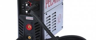
Household inverter Source klentrade.ru
This operation is possible due to the complexity of the device. In addition to the step-down transformer, the device is equipped with various filters and modulators. It has cooling coolers installed, as well as all kinds of regulators and sensors.
But despite the complexity of the circuit, it allows you to reduce the size of the transformer and significantly reduce both the dimensions of the device and its weight. In addition, the electric arc does not lose stability, and the metal melts well and forms an even seam.
Additional advantages of an inverter over a transformer:
- Electricity consumption is significantly reduced.
- Good performance with less power.
- Adjustable current, allowing you to weld not only thin, but also thick metals.
- Ability to work with alloy steels, copper and aluminum.
- The efficiency remains unchanged for a long time during continuous operation.
And the main disadvantage is the high price of inverters. In addition, the device is very capricious. Immediately reacts to a drop in ambient temperature. And due to the complexity of the configuration, repairs are difficult, which also turns into an expensive pleasure.
Classification of welding transformers
The welding transformer as technical equipment has several design options, divided mainly according to the principle of operation and purpose. The main classification criteria are:
- supply voltage: 220 or 380 V;
- number of input phases: 1 or 3 phases;
- rated welding current: for a commercially produced transformer it is up to 400 A, for special purposes there are options for 1000 A;
- rated no-load voltage: from 48 to 70 V;
- welding current supply mode: pulsed or continuous;
- sizes and weight: in a wide range - from those carried on the shoulder to powerful models that require a trolley or lifting equipment.
Operating conditions also make their own adjustments. The welding transformer can be stationary or mobile, in a regular or waterproof housing.
Design diagram and its modifications
In addition to the standard version of the device, there may be some additional components that allow the unit to be improved to a certain extent.
The welding transformer circuit can be supplemented with:
- secondary windings;
- capacitors;
- stabilizers;
- thyristor phase regulators.
In addition, a resistance can be added to the circuit, allowing you to regulate the current strength when the separation of the coils no longer gives the required result. This version of the welding machine is perfect for working with thin metal.
The resistance can be made in the form of a separate block with a set of contactors that set the required Ohm value.
It is worth noting that more than a dozen years have passed since the electric arc was first discovered and the first welding unit was created. Throughout this time, welding methods, and with them the equipment, have been constantly improved.
At the moment, there are several options, differing in varying design complexity and operating principles. When it comes to the possibility of making a welding machine with your own hands, there are two main, most popular welding options: contact and arc.
Arc welding transformers are most widely used among folk craftsmen.
Welding machine based on a transformer.
There are several reasons for this phenomenon:
- wide range of applications;
- a fairly simple design, characterized by high reliability;
- mobility and ease of use.
However, such a modification also has some disadvantages, the main of which is the low efficiency and the dependence of the welding quality on the worker’s skills.
Repair and construction work, construction of metal structures, pipe welding are just some of the areas of human activity in which manual arc welding is most widely used.
In addition, this method allows not only to connect various metal parts, but also to cut them.
The design of such units is quite simple. They consist of a transformer with primary and secondary windings, a current regulator, an electrode holder and a ground clamp.
Of course, the main component of such devices is the transformer itself. The design of this element can be different, but the most popular is a toroidal transformer with a U-shaped magnetic core.
This unit is designed as follows: the winding of the welding transformer is made of copper or aluminum wire. The number of turns, as well as the thickness of the wire, depends on the required characteristics of the device.
Spot welding, or contact welding as it is called, is somewhat different from arc welding. Naturally, the main difference lies in the method itself. In the arc version, melting occurs under the influence of an electric arc that appears between the electrode and the surface of the metal part.
In resistance welding, local heating of the product occurs at the joint due to the passage of current between two electrodes. In this embodiment, the metal also melts and joins, but this occurs only at the point of contact of the electrode with the product.
This method of joining metal workpieces has become widespread in the automotive industry, construction, etc.
In addition to the methodology itself, there are differences in the design of the central element of this device. First of all, there are no surfacing electrodes here. Instead, sharpened copper rods are used, between which the products to be connected are installed.
Transformers in such units have significantly lower power. Also, the presence of capacitors in such a device is mandatory, while in electric arc apparatuses you can do without them.
Nevertheless, regardless of which transformer will be used, the main thing is to know its characteristics. It is also important to understand what they are responsible for and how they can be changed. The table below shows some parameters of this element.
| Options | Transformer type | |||||||
| SP-1 | TSP-2 | STSH-500 | TS-500 | TD-500 | TD-300 | TD-304 | TDP-1 | |
| Mains voltage, V | 220/380 | 220/380 | 380 | 220/380 | 380 | 380 | 380 | 220/380 |
| Rated current, A | 160 | 300 | 500 | 500 | 500 | 300 | 300 | 160 |
| Welding current change interval, A | From 105 to 180 | From 90 to 300 | From 145 to 650 | From 165 to 650 | From 80 to 700 | From 60 to 400 | From 60 to 385 | From 55 to 175 |
| Rated arc voltage, V | 25 | 30 | 30 | 30 | 30 | 30 | 35 | 26,4 |
| Open circuit voltage, V | 65-70 | 62 | 60 | 60 | 60-76 | 61-79 | 61-79 | 68 |
| Rated power, kV*A | 12 | 19,4 | 33 | 32 | 32 | 19,4 | 19,4 | 11,4 |
| Device efficiency | 0,750 | 0,760 | 0,90 | 0,850 | 0,870 | 0,860 | 0,870 | 0,720 |
| Power factor cosϕ | 0,46 | 0,6 | 0,53 | 0,53 | 0,53 | 0,51 | 0,6 | 0,65 |
| Dimensions, mm | ||||||||
| Length | 254 | 510 | 670 | 840 | 515 | 692 | 692 | 435 |
| Width | 424 | 370 | 666 | 576 | 725 | 620 | 620 | 290 |
| height | 435 | 590 | 753 | 1060 | 815 | 710 | 710 | 535 |
| Weight, kg | 38 | 65 | 220 | 250 | 210 | 137 | 137 | 38 |
An important characteristic is also the number of phases and network voltage. At home, the easiest way is to use a single-phase device that can operate from a household network. In this regard, it is precisely these options that have become most widespread among craftsmen who make them themselves.
However, it is also possible to use a three-phase welding transformer, which is powered from a 380 V network. This characteristic is the main one when creating and designing a welding unit.
The rated welding current determines the capabilities of the device in welding and cutting metal parts of various thicknesses. If we are talking about a homemade transformer, then the value of this parameter does not exceed two hundred amperes. In practice, this is quite enough to perform almost any work that may arise in everyday life.
It should also be noted that a higher rated current will lead to an increase in the weight of the device. For example, an industrial transformer capable of providing a current of a thousand amperes weighs about three hundred kilograms.
Connecting metal products of different thicknesses requires a certain current value, otherwise the metal simply will not melt and connect. For these purposes, the devices are equipped with a regulator that allows you to set the welding current.
Typically, the adjustment interval is determined by the needs of using electrodes of a given diameter. In homemade devices, the current range can vary from 50 to 200 amperes.
Connecting metal workpieces of different thicknesses using the same device requires not only control of the rated current value, but also the use of electrodes of different diameters.
Design features of welding transformers.
You should be well aware of the fact that welding with thin electrodes requires a lower value of the rated welding current, and working with thick electrodes requires, on the contrary, larger values. The same applies to the thickness of the metal.
As noted earlier, the welding transformer works to reduce the voltage of the electrical network. At the output, the device produces a voltage of about eighty volts. So, in arc welding, the range of values varies from twenty to seventy volts.
It is important to understand: this parameter cannot be adjusted; it is set initially.
Devices for spot welding require an even lower voltage value of one and a half to two volts. This is quite natural, based on the relationship between voltage and current. The higher the current, the lower the voltage will be.
The key characteristic of the device is the nominal operating mode. It determines the duration of continuous operation, as well as the time required for cooling.
In homemade devices, this indicator is usually at the level of thirty percent. This means that within ten minutes you can work continuously for only three minutes, and the rest of the time the device must “rest”.
Power consumption and output are not very important parameters. Nevertheless, on their basis it is possible to calculate the efficiency factor. Naturally, the smaller the difference in these characteristics, the higher the performance.
Open circuit voltage is an important criterion for arc welding. Higher values of this parameter make it easier to trigger an arc. It was already mentioned above that usually this value does not exceed eighty volts.
It is simply impossible to do without a schematic diagram of this device when making it yourself. By and large, there should not be any particular difficulties in the design of the device, especially if we are talking about the arc method of connecting products.
With the development of microelectronics and electrical engineering, the transformer circuit was improved. You can easily find a schematic diagram of this unit on the Internet. It will definitely contain various diode bridges, regulators and, possibly, resistance blocks.
As for the scheme corresponding to the apparatus for point joining of metal workpieces, it is much more complicated. On it you can find capacitors, thyristors and diodes. All these elements allow more precise control of the current strength, as well as welding time.
There are many different schemes. You can get acquainted with them both on the World Wide Web and in specialized magazines or books.
Welding transformer circuit
To quickly (and most importantly, simply) regulate the current and voltage on the arc, it is important to use simple circuit diagrams for the design of a welding transformer. They can be classified only by technical performance.
The following design options, consisting of a minimum of components, are most often used. This makes the devices quick to repair, and any welder can work on them.
Welding equipment with shunt
Welding with such a unit is simple; its circuit consists of a “regular” base in the form of a magnetic circuit, windings and a metal element inserted into the opening of the magnetic circuit. The latter is massive and is designed to select the generated EMF. This device is used in production.
The principle of operation of the transformer shunt: if it is necessary to reduce the current strength, it is supplied to the magnetic circuit mechanically to the calculated position. The magnetic field also begins to dissipate on it, the total resistance of the electrical circuit changes, which immediately affects the voltage and current.
The whole point is to change the gaps from the edge of the magnetic circuit to the shunt. Due to the decreasing air resistance, part of the magnetic flux passes to the shunt - and does not reach the secondary winding.
Welding transformers with sectional windings
This design includes several windings at once, each of which is a stage for regulation. Each stage has a different number of turns, which, when connected to a circuit, allows it to generate an electric current of varying strength.
The principle of this circuit is to combine the existing stages on the windings to obtain the necessary current-voltage characteristics of the welding arc.
The relative position of the windings is done to reduce bulk. They are wound on top of each other or side by side. To connect, contacts are displayed on a kind of remote control; the required configuration is made using switches.
Full tuning is achieved by the presence of steps in both the secondary and primary windings.
Thyristor welding transformers
The parameters of the welding arc are regulated by the thyristor. The essence of its work is to change the average voltage with alternating current.
Structurally, such a “superstructure” consists of a pair of thyristors, configured symmetrically and mounted towards each other. This ensures strict current-voltage characteristics.
The circuit is characterized by significant efficiency, since when installed on the primary winding, losses from voltage drop will be higher. At the same time, the rated currents in the thyristors themselves are significantly lower.
Classification by characteristics
Typically, units are divided into 3 types. Based on the operating principle of a welding transformer. Or rather, its control node. There are amplitude control devices with normal or increased dispersion. The first option contains a choke. The second is more complex because, in addition to the reactive winding, it has a voltage stabilizer and capacitors.
In the third type, the current is controlled by thyristors. Sometimes another transformer is built into such devices for recharge. It is needed for arc stability. Or this role is taken on by a pulse stabilizer.
Otherwise, all types of welding transformers can be classified according to the following criteria:
- Network voltage. Household appliances operate from a 220 V line. Industrial appliances are powered from a three-phase network of 380 V. Combined versions of units are also produced.
- Functionality. Directly depends on the current strength. Only industrial transformers can generate over 300 A. If the current strength is lower, then the unit can no longer cope with thick metal.
Working on a multi-station apparatus Source ligasvarki.ru
- Number of work posts. This indicator determines how many welding cables can be connected to the machine. There are multi-station units that allow six welders to work simultaneously.
- Adjustment method. It depends on the composition of the control node.
In view of the above, we can formulate recommendations for choosing a welding transformer for domestic needs. A single-phase device with a regulating saturation choke is suitable for home use. It is better to select a single-station unit with an output current of at least 300 A. This will be useful if you have to work with thick metal.
Basic malfunctions and methods for their elimination
Welding transformers are technical equipment, so deviations and malfunctions are always possible in them. What course of action to take in the absence of adequate operation of the device should be determined by the situation.
- the transformer turns off by itself: you need to check the wires and their insulation, connections and all parts - the problem most often lies in loss of power or leaky electrical protection (short circuits or voltage breakdowns when it increases during switching on);
- the humming exceeds the usual level: you should tighten the fasteners of the magnetic circuit and coils, check the insulation - the mechanics are very likely to become loose, or check the welding mode down to the type and diameter of the electrode;
- the transformer began to get very hot: re-evaluate its operating mode - most likely, welding is not carried out according to design conditions, at increased current and for too large thicknesses, and also without observing the ratio of time under load and cooling time;
- the contacts overheat: you should clean all connections (after disconnecting the device from the network), assemble them tightly and update the wires if necessary - this leads to deterioration of the connection in the connections;
- the welding current turns out to be higher or lower than the calculated one: check the machine settings regarding the regulatory components, use the stabilizer - they are the ones who create the current;
- the welding current is poorly regulated: the regulating component (choke, windings) should be checked for mechanical damage or voltage breakdown;
- the welding arc goes out and is difficult to re-ignite: checking the entire electrical circuit with special attention to the insulation and condition of the connections - most likely there is a short circuit somewhere;
- after removing the load, the transformer consumes a huge amount of energy: a full check of the windings - a short circuit between individual wires is very likely.
Determination of the malfunction should be done with the voltage removed and after disconnection from the power source. If after checking these options there are still faults, the answer will be given in an electrical workshop.
Bottom line
The transformer is the central unit of any welding machine. Its main task is to reduce the voltage and simultaneously increase the current to the required value. Thanks to this, it becomes possible to connect metal products with each other.
The design of the welding transformer is quite simple. At the moment, you can find a large number of implementation schemes for this element on the Internet. So it can be assembled even at home. However, for this it is necessary to correctly calculate the welding transformer.
Advantages and disadvantages of welding transformers
The main “advantages” of a welding transformer are as follows:
- versatility: can be used for a huge number of welding and surfacing options (restoration of parts), but only for ferrous metals;
- relatively economical energy consumption with a well-chosen unit and high-quality efficiency (up to 80-90%);
- high ease of maintenance and maintainability in almost any conditions;
- low cost;
- absence of critical requirements for application conditions.
There are also disadvantages of a transformer welding machine:
- significant dependence on voltage changes in the power source - for this it is optimal to use a stabilizer (built-in or separate), which will lead to leveling of the arc;
- strong splashing of molten metal;
- high dependence of the weld on the qualifications of the welder;
- not used for welding non-ferrous alloys;
- significant weight and dimensions.
Differences and types of equipment
The following types of welding machines are used in production:
Types of welding equipment
- transformers;
- rectifiers;
- inverters.
They also highlight:
- semi-automatic;
- generators - welding machines with a gasoline or diesel electric generator;
- and other industrial devices.
How to choose a welding transformer
A welding transformer is not just a ready-made unit; it must be selected for the planned work. This can be done by taking into account the following points:
- place of application and purpose: household (short-term use, current - up to 200 A), professional (can work for a long time, current - up to 300-350 A), industrial (continuous use at currents up to 1000 A);
- power supply voltage: household network with 220 V (plus or minus 10%) or industrial with 380 V;
- customization options: the more there are and the wider the control intervals, the better the result will be;
- power consumption: the greater it is, the better the transformer functions, but you should not forget about the power supply capabilities;
- duration of active work: welding with household models can be carried out for up to 30 minutes, after which the device will have to cool for the same amount of time; for industrial models, welding continues for hours;
- ability to work with a range of electrodes: the transformer is calculated according to the diameter of the rod up to a certain value
- price: saving with the cheapest is not worth it.
Khafizov Ildar
Level IV NAKS specialist
Ask a Question
For installation work, it is better to consider using an inverter, since their size and weight are less, which is important. Also, the use of an inverter ensures high stability of the process, and as a result, a better quality seam.
What to look for when choosing
You must understand that choosing welding equipment is not an easy task and is solved in several stages.
- It is necessary to know the brand of materials being welded and the type of seam required. So, for processing steel or stainless steel, a machine that provides manual arc welding is sufficient. For welding ordinary steel, you can use machines with alternating and direct current. To work with stainless steel, it is necessary to use direct current devices. The performance characteristics of the welding transformer allow you to work with different materials.
- Depending on the size of the current, devices of 200 A are classified as household, and those of 300 are classified as professional.
- Depending on the type of work, semi-automatic machines, which have a complex design and a fairly high cost, show high productivity and ease of operation.
- Inverters are small in size and weight and have a wide range of settings.
- The location of the work, in particular the climatic conditions, is of no small importance.
- Of course, when deciding on choosing a device, you need to pay attention to the manufacturer.
How to make a welding transformer with your own hands
Before physical work, it is important to determine the design and parameters of the product.
Sheets of transformer iron are taken as the basis - if you don’t have this at hand, it is recommended to purchase suitable blanks. The use of ordinary sheet steel will not bring sufficient results. You can take parts of old transformers.
The magnetic core should be made in a closed shape - a square or rectangle, they are more practical than a circle.
To create windings, it is important to select copper wires with high heat resistance. The insulation of this type should be fiberglass or cotton - rubber is not allowed. The cross-section of the wire for the primary winding is about 5-6 square meters. mm, which will allow you to get up to 25 A here.
The cross section for the secondary winding is about 30-35 square meters. mm, a significant welding current will flow here. Insulation must be as reliable as possible.
The windings are made in the same direction. It is necessary to lay additional insulation between the rows - cotton fabric or specially impregnated transformer paper is optimal.
The magnetic core equipped with windings is placed in a steel case. The fasteners are also insulated to prevent current leakage and short circuits. It is important to make the housing with ventilation openings - the transformer gets hot during operation and needs to release heat.
The input and output terminals are fixed in the housing and protected by insulating materials. The switching and control elements should be located on the side plane - not on the top.
For guaranteed quality and to prevent short circuits, it is better to buy factory transformers.
How to mount the device yourself
The main part of a homemade unit is the core. It is made of transformer steel, which is quite difficult to buy. The resulting structure has the shape of a rectangle with a cross-section of more than 55 cm². When forming the primary and secondary coils, install the adjusting screw. It is used to move the movable winding.
The wire cross-section of the first coil must be more than 5 mm². To assemble the transformer, cables with heat-resistant insulation are used.
The secondary winding is formed from a copper conductor with a cross section of 30 mm². At the last stage, a textolite body is assembled, which serves to protect the welder from electric shock.
Methods for regulating the strength of welding current
One of the main transformer parts is the adjustment unit, consisting of a saturation choke. It adjusts the strength of the welding current by changing the distance between the coils. But there are other ways to regulate this indicator.
Adjustment of the strength of the welding current is carried out not only using a saturation choke.
You can use a magnetic gap choke, a movable or magnetized shunt, a reactive or dissipative winding, or a movable type of capacitor coil. As well as thyristor regulators or pulse stabilizers.
Varieties of transformer models provide the opportunity to choose the one that suits you. When determining which model to take, it is worth proceeding from the work tasks for which it will be used.
For household work, a single-phase single-station welding unit with a current strength of up to 300A and adjustment by a saturation choke is suitable. These models are easy to use and store.
The structure of the transformer apparatus and the principles of its use
The transformer consists of 2 units: transformer and regulator. The first is designed to reduce the voltage level that comes from the 220-380V power supply. The second is responsible for setting the required current strength.
There are several types of transformer units. They depend on the voltage level that ensures stable operation of the device. There are three main types of transformers: single-phase, two-phase and three-phase.
The single-phase model is equipped with a core and two windings. A two-phase one consists of two single-phase elements, and a three-phase one contains three single-phase elements.
The control unit consists of a saturation choke. The current is adjusted by changing the gap of the choke magnetic circuit. To do this, you need to remove the case cover, which is not very convenient.
Therefore, craftsmen often modify the transformer on their own, equipping it with an external handle, which is used to regulate the current strength mechanically.
Transformer and control units are the basis of a welding transformer. However, besides them, it includes other devices.
They do not complicate the mechanism too much, so devices of this type rarely suffer from malfunctions. And in the event of a breakdown, you can carry out repairs yourself.