Countersink. Purpose and types of tools
A countersink is a tool designed for semi-finishing metal. Externally, it is a metal shaft with cutting surfaces, reminiscent of a drill. It is created specifically for the metalworking industry. Produced in accordance with GOST 12489-71, GOST 3231-71 or TU 2-035-923-83 in accordance with the type of device.
Download GOST 12489-71
Download GOST 3231-71
Countersinks are divided into:
By type of fastening in the machine chuck:
- tail;
- mounted
By design features:
- solid;
- prefabricated;
- welded;
- with and without carbide inserts.
By geometric shape:
- cylindrical;
- conical;
- reverse.
In the direction of the ribbons and grooves:
- right rotation;
- left rotation.
Solid shank countersinks are most similar to drills, but differ in the presence of more cutting edges. In their cross section there are from 3 to 6 such sharp teeth. For production, high-speed tool steels R9, R18 are used, as well as alloy plates with increased hardness and wear resistance VK4, VK6, VK8, T15K6. The permissible cutting speed for models with carbide inserts is higher, which increases their efficiency.
Mounted countersinks do not have a tail and are attached using a mandrel, for which a groove is provided in the body of the tool.
There are strictly 4 teeth in diameter. The nozzle itself is sometimes equipped with removable working blades made of hard alloys. The cutters are fixed with wedges and can be replaced as needed.
A conical countersink is similar to a drill; the working part of the tool tapers towards its end. Used for processing inclined circular surfaces. Manufactured from alloy steel and metal-ceramics.
The ribbons of the countersink drill can be twisted in different directions; accordingly, the profiles of right and left rotation are distinguished. Left-hand rotation countersinks are used in semi-automatic lathes that feed material from the right side.
The choice of type of countersink is directly determined by the size of the hole in the workpiece and its material. With a diameter of up to 12 mm, they work with solid countersinks, starting from 20 mm - with countersink attachments and tools with inserted alloy blades. When it is necessary to make smoother and larger holes, combined models are installed in the machine, where there can be up to eight sharp teeth, and these countersinks are optionally combined with drills, reamers and other drilling and cutting tools.
Applications and types of countersinks
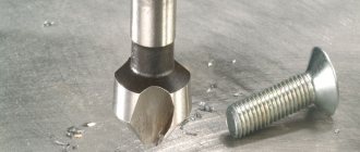
A countersink is a multi-bladed, multi-toothed cutting tool used for finishing pre-made round holes in parts and workpieces made of different materials (pictured). Processing by this method is used to increase the diameter and obtain a better surface of the hole by cutting.
This process is called countersinking. The cutting method is similar to the drilling procedure: the same rotation of the countersinking equipment around its axis and simultaneous translational movement of the tool along the axis are observed.
Countersink with carbide inserts
We developed a countersink for the metalworking industry to process drilled, slotted or stamped holes. A countersink for metal, the requirements for the characteristics of which are regulated by GOST 12489-71, is used when performing intermediate or final processing. In this regard, there are two types of tools:
- for subsequent deployment with allowance;
- to obtain a high-precision hole - with quality H11 (tolerance 4–5 accuracy classes).
You can familiarize yourself with the GOST requirements for countersinks by downloading the document in pdf format from the link below.
GOST 12489-71 Solid countersinks. Design and dimensions
When using a boring tool, the diameter increases, surface accuracy and hole cleanliness improve. Countersinking is intended mainly for:
- achieving a smoother, cleaner hole surface before reaming or tapping;
- calibrating the hole for a bolt, stud or any other fastener.
Countersinks are used, the requirements for which are determined by GOST 12489-71, also when processing end surfaces and when performing certain operations that give the hole the desired profile (for example, expanding the recess in the upper part of the hole intended for bolt heads).
Countersinks are divided into several types according to the method of their fastening into the machine:
- mounted;
- shank (with a metric taper or with a Morse taper - types of shank for mounting in a machine).
Diamond countersink
By design, countersinks are of the following types:
- prefabricated;
- solid;
- welded;
- with carbide plates.
A solid countersink is similar to a drill, so its second name is a countersink drill. It has more spiral flutes and cutting edges (3 to 6 teeth) than a simple drill. The cutting part of the tool, as stipulated by GOST 12489-71, is made of high-speed steel P18, P9 or made with carbide inserts (BK4, BK6, BK8 for processing cast iron, T15K6 for processing steel). Tools equipped with carbide inserts have greater productivity (higher cutting speed) than those made of high-speed steel.
There are also conical countersinks (for processing surfaces of a conical configuration) and the so-called reverse type of countersinks.
Spiral tail countersinks
The difference between countersinking and related operations
Countersinking is similar to reaming holes; the cutting edges of the tool remove excess material from the stenoctium, reduce roughness and increase the diameter. This is a semi-finish operation, which means it is followed by another processing step. Deployment is the final procedure. During countersinking, defects in drilling, stamping and casting are eliminated. In the process, you can slightly adjust the binding to achieve better alignment for the future connection. Accuracy can be increased to 5, and sometimes even to 4th class.
When setting the cutting mode, you need to remember that the thickness of the metal removed during countersinking is equal to half the allowance for a given hole diameter. Compared to drilling, the feed can be made 1.5-2 times larger, but the speed can remain the same. Specific cutting parameters are calculated using formulas given in the regulatory literature.
Since a countersink has greater rigidity compared to a drill, due to the increased number of sharp protrusions, the accuracy of the direction of movement increases, as well as the quality of processing, smoothness and cleanliness of the surface. For comparison, drilling gives a roughness of 20 microns and grades 11–12, countersinking gives a roughness of 2.5 microns, grades 9–11, and reaming gives a roughness of 0.25-1.25 microns and grades 6–9. Quality is the precision of manufacturing a part; as its value increases, tolerances increase and accuracy decreases. If the technological process for processing a product requires both countersinking and reaming, then they are performed in one installation and alignment of the workpiece on the machine.
Countersinking and countersinking are often confused due to the similarity of names. In fact, countersinking has a completely different purpose, and it uses a great tool called a countersink.
This type of machining creates recesses to accommodate fasteners flush with the surface of the part. In addition to chamfering, a countersink is used to cut conical-shaped recesses. Another purpose will be to clean and process recesses before installing fasteners; this is done using flat or end countersinks, also called counterbores, which is more correct.
The most widely used on the market are conical countersinks with working angles of 90 and 120º, which create recesses to hide the heads of bolts and screws. In the metalworking industry, countersinks with a flat tip are also used, used for cleaning recesses for fasteners. Countersinks are installed in the same machines as other tools for processing holes for fasteners.
Countersinking, countersinking and reaming
To increase the diameter of a hole obtained by drilling, casting or stamping, as well as to obtain conical and cylindrical recesses, and to clean the end surfaces of bosses and hubs, the following technological operations are used: countersinking, countersinking and countersinking (Fig. 9.1).
Countersinking is the process of processing pre-drilled, stamped, cast holes in order to give them a more correct geometric shape (eliminate deviations from roundness and other defects), achieve higher accuracy (9...11th grade) and reduce surface roughness to Ra = 1, 25…2.5 µm. This processing can be either final or intermediate (semi-finishing) before reaming, giving even more accurate holes (6...9 grades) and surface roughness up to Ra = 0.16...1.25 microns. When processing precision holes with a diameter of less than 12 mm, reaming is used instead of countersinking.
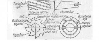
The nature of the work of a countersink is similar to the nature of the work of a drill when drilling a hole. In terms of design and design of the cutting edges, the countersink is somewhat different from the drill and has three to four teeth, which ensures the correct and more stable position of the countersink relative to the axis of the hole being machined.
| Figure 9.17 Designs and elements of countersinks |
According to the design, countersinks can be solid (Fig. 9.17, a) and mounted (Fig. 9.17, b).
To save high-speed steel, countersinks are also made with inserted knives or with soldered carbide plates. Countering is the process of processing with a special tool - countersinking conical recesses and chamfers for the heads of bolts, screws, and rivets. Unlike countersinks, countersinks have cutting teeth at the end, sometimes and guide pins, with which the countersinks are inserted into the drilled hole, which ensures that the axis of the hole coincides with the recess formed by the countersink for the screw head. Fastening countersinks and countersinks on drilling machines is no different from fastening drills.
Reaming is the process of final finishing of holes, providing high dimensional accuracy and surface roughness within the range of Ra = 1.25...0.16 microns. Reaming of holes is carried out both on drilling and other metalworking machines, and manually during metalworking and metalworking. Manual reamers (Fig. 9.18, a) - with straight and screw teeth, mounted, adjustable - equipped with a square end on the shank for rotating them using a crank.
| Figure 9.18 Types of sweeps |
The pitch of the reamer teeth (angular pitch) is uneven, which ensures a less rough and wavy surface of the hole and reduces the possibility of the formation of a polyhedral rather than a cylindrical hole.
Reamers used on machines are called machine reamers and differ from manual reamers by a shorter working part and the presence of a tapered shank (Fig. 9.18, b). They are fixed in floating (oscillating) mandrels or cartridges, which provides the reamer with the ability to self-align along the axis of the drilled hole and reduces the breakdown of the hole. To process conical holes, most often for Morse cones, conical manual reamers are used in sets of two or three pieces (Fig. 9.18, c). The first development is rough (grinding), the second is intermediate and the third is finishing (final), giving the hole its final dimensions and the required surface roughness.
The main parts and geometric parameters of manual development are shown in Fig. 9.19. The allowance for reaming should be no more than 0.05...0.1 mm per side. A larger allowance can lead to rapid dulling of the reamer, increasing the roughness of the hole surface and reducing machining accuracy.
| Figure 9.19 Parts and elements of manual reamers |
Manual hole reaming exercises involve performing a number of techniques. When starting to unravel, you must: select the required reamer (check its markings), make sure there are no nicks or chipped places on the cutting edges, secure the workpiece in a vice or install it on a workbench (plate) in a position convenient for work, take a rough reamer , lubricate the intake part with mineral oil and insert it into the hole without distortion, check the position of the reamer with a square (900), put a knob on the square of the reamer shank, lightly pressing the reamer down with your right hand, slowly rotate the knob with your left hand clockwise, periodically removing the reamer from the hole to clean it from chips and lubricate it, finish reaming when ¾ of the working part of the reamer comes out of the hole. When reaming deep holes located in hard-to-reach places on the part, it is necessary to use special extensions that fit onto the square of the reamer shank.
The final (finish) deployment is carried out in the same sequence.
The driver must be rotated slowly, smoothly and without jerking. Rotating the reamer in the opposite direction is unacceptable, as it can cause scoring on the surface of the hole or breakage of the cutting edges of the reamer.
Methods of deployment using manual reamers are shown in Fig. 9.20, a...c.
Machine reaming exercises are performed on drilling machines in the same way as drilling. Reaming is best done immediately after drilling and countersinking with one installation of the workpiece in a vice or fixture. The reamer is secured using a chuck or adapter bushings in the cone of the machine spindle. In some cases, to ensure more accurate alignment of the reamer axes, they are fixed in floating (oscillating) holders. The cutting speed (spindle rotation speed) during reaming should be 2…3 times less than when drilling with a drill of the same diameter. Reaming is carried out with a mechanical feed, which depends on the diameter of the reamer, the material of the workpiece and is accepted within the range of 0.5...2.0 mm/rev. The following is used as a cutting fluid: when processing steel and bronze workpieces - a solution of emulsol, sulforesol, mineral oil; when processing cast iron and aluminum alloys - kerosene, turpentine; when processing malleable cast iron and brass - emulsol solution. Exercises in machine countersinking, countersinking and reaming can in some cases be combined with drilling exercises on drilling machines.
The quality of the surface of the reamed hole is checked after thorough wiping by external inspection “to the light” to detect scoring, cutting, and traces of crushing. The accuracy of the hole is determined depending on its size and the required quality of accuracy using plug gauges, indicator bore gauges, and for holes with a diameter of more than 50 mm - micrometric bore gauges.
The safety rules for reaming, countersinking and countersinking are the same as for drilling.
How to countersink metal correctly
If an amateur craftsman can take a drill and a drill for countersinking, then in an industrial environment the following machines can be used for this:
- drilling;
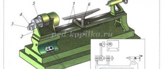
- turning;
- boring;
- milling;
- aggregate.
The countersinking process takes place in strict accordance with the technology, the general points of which can be described in the form of the following recommendations:
- In cast parts with an uneven margin for subsequent metalworking, it is necessary to bore the hole to a depth of 5–10 mm for the correct direction of movement of the cutting tool.
- For the countersinking operation, an allowance of 1–3 mm is left, depending on the final diameter.
- Countersinking of steel products is not complete without cooling with special oil solutions. When working with cast iron, as well as non-ferrous metal, it is not mandatory.
- The optimal version of the countersink and the operating mode are selected taking into account the required hole diameter, processing accuracy, its depth, the metal of the part and the options of the production machine.
- The cutting tool mount must fit into the slot that is on the workstation.
- In the case where finishing processing by reaming is expected, then during countersinking a part of the allowance, from 0.15 to 0.3 mm, is left for further work.
- To process products made of hardened and alloyed steels, countersinks with carbide inserts with a diameter of 14-50 mm and 3-4 teeth are used.
- When processing non-ferrous metals and iron alloys with a high carbon content, feather countersinks are used.
- High-speed steel tools are used to process products made from ordinary structural steel. For holes larger than 40 mm, the equipment is supplemented with nozzles with a diameter of 32–80 mm.
The discrepancy between the process and the established technology is often the cause of defects. If the tool wears out a lot, the resulting hole will be smaller than the design. When the master has overestimated the feed, or waste has stuck to the teeth of the countersink, the cleanliness of the processing may not satisfy the quality. Other defects: part of the surface is not processed, the resulting diameter is larger than required, are the result of an incorrect choice of countersink or its incorrect installation.
Lecture on the topic: “Countersinking, countersinking, reaming”
Topic: “Countersinking. Countersinking and reaming"
Countersinking is an operation for processing finished holes in castings, stampings or after drilling to obtain cylindrical or conical holes of high accuracy and low roughness.
Countersinking is performed on drilling machines with special tools - countersinks (Fig. 166). Cylindrical countersinks of various diameters are used to produce cylindrical holes.
Rice. 166. Countersinks:
a - solid; b - mounted
Conical countersinks with a cone angle at the apex of 60, 75, 90 and 120° are used to produce conical recesses. Countersinks have a guide pin that fits into the hole, ensuring that the hole axis aligns accurately with the cylindrical hole formed by the countersink.
The allowance for countersinking depends on the diameter of the countersink:
— Countersink diameter D, mm……up to 15 15 20 25 30 40 50 — Allowance per side, mm…… 0.5 1 1 1.5 1.5 2 2.5
Knowing the diameter, the material from which the countersink is made, and the grade of the metal being processed, you can select the cutting mode (Table 3).
Table 3.
Cutting speed (m/min) and rotation speed (rpm) of the countersink (carbon structural steel σ in = 650 MPa; countersinks made of P18 steel; operation with cooling)
Example.
Select the cutting speed and rotation frequency according to the table when countersinking a drilled hole D = 13 mm by D = 15 mm in carbon structural steel σв = 650 MPa (countersink D = 15 mm solid, t = 1 mm, made of P18 steel; work with cooling ; drilling machine 2118).
Selection order:
Having set the feed s = 0.2 mm/rev and knowing D = 15 mm, from the table we find the cutting speed v = 41.6 m/min and the rotation speed n - 883 rpm.
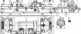
Using the kinematic diagram (see Fig. 152), we select a suitable spindle speed (735 rpm), move the belt and set the machine to the selected feed.
Rice. 167. Conical countersinking of holes
Conical countersinking (Fig. 167) is carried out in a certain sequence.
1. The choice of a conical countersink is made according to the taper of the head of the screw or rivet, which must exactly match the angle of the countersink. Before you begin, you need to check that all the countersink teeth are present and that the cutting edges are sharp.
2. When installing a countersink into the spindle of a drilling machine, take into account the cone on the countersink and the cone in the machine spindle (if necessary, select adapter cone bushings); wipe the conical shank of the countersink and the spindle cone; insert the countersink shank into the conical hole of the machine spindle in the same way as a drill with a conical shank; turn on the electric motor and check the countersink for runout. The reasons for the countersink beating can be a worn shank or a loose fit in the tapered hole of the spindle.
3. You can fix the part on the machine table in various ways, depending on the configuration of the product and the ease of fastening. When installing a part, you need to pay attention to the horizontal position of the plane, the accuracy of the alignment of the countersink axis with the axis of the hole made, and the reliability of fastening the part.
4. The countersinking operation is as follows:
a) turn on the machine engine and, lowering the quill with spindle, bring the countersink to the hole of the part;
b) when feeding manually, test countersinking is performed;
c) finalize the hole to the required depth. In this case, the depth of countersinking is determined by a limiter or a measuring ruler.
To obtain a conical surface of low roughness, countersinking is performed with a small manual feed and using a coolant (as with drilling).
Cylindrical countersinking (Fig. 168) is performed in the same sequence as conical, but it has some features.
Rice. 168. Cylindrical countersinking of holes
The diameter of the cylindrical countersink should be 0.2-0.5 mm larger than the diameter of the cylindrical head of the screw. The guide cone of the countersink must match the diameter of the screw. With a smaller diameter of the countersink guide end, the cylindrical part of the recess may be pulled to the side.
The accuracy of the cylindrical recesses is checked with a plug gauge, and the depth is checked with a caliper depth gauge (for cylindrical countersinking). When placing a countersunk screw head into a conical recess, the plane of the head must coincide with the plane of the part and fit tightly to the recess (with conical countersinking).
Countersinking is performed in the same ways. It is an operation for processing finished holes by deepening countersunk heads of screws and rivets, expanding cylindrical holes, and removing burrs from the edges of holes. This operation is performed on drilling machines using cutting tools called countersinks (Fig. 169). According to the shape of the cutting part, countersinks are divided into cylindrical and conical. Cylindrical countersinks with end teeth are used to widen holes for screw heads, flat washers, and also for making ledges in holes. These countersinks have a guide pin, which, when processed, fits into the drilled hole, ensuring that the axis of the hole accurately aligns with the cylindrical hole formed by the countersink.
Rice. 169. Countersinks:
a - conical: b - cylindrical
Conical countersinks are designed to remove burrs in the outlet part of the hole, obtaining a conical recess for the heads of screws and rivets.