Checking the stator of the angle grinder
The stator is the stationary part of the electric motor, created to create an electric field where the rotor (the moving part of the motor) rotates. Among the probable circumstances of a malfunction of an angle grinder - angle grinder, "grinder" - is a break, or a short circuit of the turns of the stator winding (coil).
Causes of breakdowns
408-105 Stator for Hitachi G18SE3 and HAMMER angle grinders. Photo 220Volt
The most common cause of failure of the stator of an angle grinder is a violation of operating conditions . Asynchronous motors have the ability to maintain speed regardless of the magnitude of the current load. This is both an advantage and a disadvantage.
The ability to perform work under heavy loads is accompanied by overheating of the tool , which during long-term operation contributes to the occurrence of malfunctions in the rotor and stator windings . Under the influence of high temperatures, the protective layer of the insulating coating burns out, which leads to failure of electrical components.
Checking with a multimeter
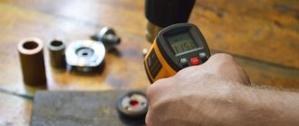
You can verify the serviceability of the stator using a device - a multimeter. This is a universal measuring device. Of course, they measure several electronic quantities: voltage, current, resistance. The device consists of a housing where the screen, switch and sockets are located, and two cords with probes (positive and negative). The negative probe is always connected to the lower socket, and the positive one to the middle or upper socket, depending on the current strength in the device being tested.
To check the stator
Angle grinders (grinders) need to set the resistance value on the multimeter from 20 to 200 Ohms and alternately bring the probes of the measuring device to the windings. If the resistance is the same everywhere, then the coil is working. When the device indicates a different resistance at certain points, then there is of course a short circuit in the winding, or a break in one book of turns. The stator is checked in the same way with an ohmmeter. Its difference from a multimeter lies only in the fact that this device can only measure resistance.
How to call
For high-quality diagnostics of the angle grinder stator, you should completely disassemble the power tool in order to remove all other structural elements, including the rotor, to ensure free access to all its parts. At the initial stage, it is necessary to perform a visual inspection. For a more complete picture, you should definitely check for defects using electrical instruments. What devices and how to ring the stator of an angle grinder are described in detail at the link “How to ring the stator of an angle grinder.”
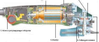
Diagnostics of the mechanical part of an angle grinder
Most often, bearings and gears are repaired or replaced in the mechanical part of the angle grinder (see figure below). Wear and failure of these parts is usually accompanied by increased vibration, unusual sounds or gearbox jamming. Diagnosis of their condition is carried out visually after complete disassembly of the case, and based on its results, a decision is made on the need and type of repair.
In addition, the gearboxes of angle grinders use protective couplings that prevent a sharp jerk of the housing when the disk jams. Such devices are initially designed to operate in extreme conditions and, as a rule, require repair very rarely.
Checking the gears of the gearbox
In order to inspect the gears of the angle grinder gearbox, it is necessary to separate it from the drive and then completely disassemble it. Diagnostics consists of visually determining the degree of tooth wear, and repair involves replacing the worn-out gear with a new one. The main types of gear malfunctions that require gearbox repair are grinding and chipping of teeth.
Checking the lock button
The angle grinder spindle lock (locking button) is necessary to hold it stationary when tightening the clamping nut. If it starts to sink, you need to remove the button, remove the rod and spring, and then clean the inside and visually check the condition of the rod, seal and spring. Repairing the retainer usually involves replacing one of these components (see video).
Checking the disk mounting flange
The usual support flange of an angle grinder is a simple device in the form of a disk, against which a cutting wheel is pressed. Its surface should be smooth, without potholes or burrs. It cannot be repaired, and when worn out it is simply replaced with a new one.
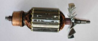
Checking the rotor bearings
The bearing of the drive shaft of the angle grinder, which is the rotor shaft of the electric motor, can be inspected and replaced without completely disassembling the gearbox. To do this, it is enough to disconnect the gearbox and drive housing (see figure above). If the decision is made to repair and replace the bearing, then you will have to completely remove the electric motor rotor, remove the drive gear (see photo below), and then remove the old one and install a new bearing.
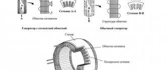
Winding diagram, how to choose wire thickness
The stators of angle grinders have a very similar design and differ in the size of the parts in which the magnetic flux is formed, the number of turns in the windings and the diameter of the wire. The standard connection diagram for grinders is shown in the following figure.
Here L1 and L2 denote the stator coils.
The burnt winding is removed, and it is necessary to collect information about the old coils : determine the number of turns, wire diameter, beginning, end of the winding and the required direction during rewinding work. The number of turns is determined by direct counting of wires after cutting the failed coils.
The diameter of the wire should match the windings being replaced as closely as possible. Therefore, the most suitable measuring tool is a micrometer with a measurement accuracy of up to 0.01 mm. The measurement is carried out on the surface of the wire of the burnt coil, stripped of the insulating coating.
How to rewind at home, stages of work
Repair begins with removing the failed old winding . Using pliers (pliers, round nose pliers) the stator slots are freed from the old winding.
Next, the stator coils are rewinded . It can be performed on a specially manufactured template or directly into the grooves of the stator core. This depends on the depth and width of the space for laying the wire.
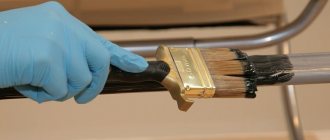
The wound coil is installed in the stator with the obligatory positioning of the beginning and end of the winding wire, as described above in the text. The winding is fixed in the stator with all gaps maintained (fastening options will be discussed further in the videos below). The stator is heated in the oven to approximately 80°C - 110°C. Using a brush, apply varnish or pre-prepared epoxy resin with a hardener. When applying, it is important to achieve the deepest possible penetration of the impregnation.
Practical advice on rewinding stator windings is given in the following videos.
Rewinding reels using a template
The author of the following video restores the stator of an angle grinder of the Temp model using items that can be easily found in any household. So the base (template) for winding the wire was a can of air freshener. Important : the diameter of the canister must correspond to the diameter of the wire sample formed according to the dimensions of the stator grooves.
Rewinding windings directly on the core
The following video describes in detail the technology for repairing the stator of an angle grinder . The author shows all stages of work and argues for his choice of rewinding the winding directly on the hardware. This model has wide grooves , and it will be difficult to fit the finished coil tightly into them. The author uses a plate as a guiding device, which he bends to the height of the corresponding extreme point of laying the winding in the grooves. The surface of the plate is covered with electrical tape to protect the wire insulation from damage and is fixed to the core with the same electrical tape. The process of such rewinding is quite labor-intensive. With a large number of turns, you should record your actions , for example, with appropriate notes on paper. This will help avoid mistakes.
After winding is completed and the guide plate is removed, the coil may weaken its laying due to residual stresses, and individual turns may fall out of the total mass. In this case, tying with a thread made of natural material (synthetics cannot be used) will help maintain the winding density. The use of various wedge objects allows you to fit the coil tightly into the grooves. However, the author does not encourage their use, as this negatively affects the quality of impregnation.
It's not always possible to choose the right template
In the following video, the author warns those who do do-it-yourself rewinding about the difficulties in choosing a template . It is not always possible to choose the right one right away. Guaranteed high-quality rewinding is provided by a much more labor-intensive but reliable method directly on the hardware.
Repair technology with a detailed description of varnish impregnation after rewinding
The author of the following video describes all stages of work: from disassembling, determining the number of turns, selecting wire material to rewinding using a template and impregnating the assembled stator with varnish. The impregnation process , which is carried out with ordinary varnish for interior work, is shown in detail The best option, of course, is to use shellac , which has good insulating properties. However, since some times this varnish has become a scarce material.
Source
Diagram of a device for checking turn-to-turn short circuits
The device circuit was described in Radio magazine No. 7 for 1990, but has not yet lost its relevance due to its simplicity and reliability. With such a parting, checking the interturn closure is carried out in a matter of seconds.
The tester assembled for the site differs slightly from this scheme. We read about the changes made to the scheme at the end of the article.
The tester is based on a measuring generator. It is assembled on transistors VT1, VT2. The frequency of this generator is not constant and depends on the oscillatory circuit, which is formed by capacitor C1, as well as the connected coil, it is connected to XP1 and XP2. Resistor R1 sets the required depth of positive feedback to ensure reliable operation of the measuring generator. VT3 is switched on in diode mode, it creates the desired voltage shift between the emitter of VT2 and the base of VT4.
When assembling the device, it is advisable to check the correctness of the circuit gradually. The functionality of the pulse generator can be checked by connecting a 1 kOhm variable resistor, as shown in the diagram. By rotating the slider of this resistor you can make sure that the pulse generator works correctly in all modes
When setting the resistance to 200-300 Ohms, it is important to make sure that the LED blinks
The tester works as follows. If the tester terminals are closed, the measuring generator is not excited at all, VT2 will be open. The voltage at the emitter of VT2, which means that based on the transistor VT4, will not be enough to make the pulse generator work. In this case, VT5, VT6 will be open, and the diode will light constantly, which indicates the integrity of the circuit.
If a working coil is connected to the measuring terminals of the device, let’s say, the transformer is checked for an interturn short circuit, and by making an adjustment using R1, the measuring generator will begin to be excited. At the emitter of VT2, the voltage will increase, all this will lead to an increase in the bias voltage at the base of VT4, as well as the start of the pulse generator. The diode should blink.
If it turns out that the winding being tested has short-circuited turns, then the measuring generator will not be excited, and the device will work in the same way as in the case of short-circuited terminals (the control diode will light up).
When the measuring leads are disconnected or there is a break, then VT2 will be closed. The voltage at its emitter, which means that at the base of VT4, increases. It opens to saturation, and the oscillations of the pulse generator will be disrupted. VT5, VT6 will close, and the control diode will not light up at all.
Another feature of this tester is the ability to test pn junctions. When connecting a silicon diode or transistor to the device (anode to XP1, cathode to XP2), the control LED should blink. In the event of a breakdown, the LED simply lights up, and in the event of a break, it does not light up.
Instead of VT1-VT3 you can install KT358V or KT312V. KT361B can be easily replaced with KT502, KT209. When using an LED, it is necessary to connect a resistance of about 30-60 Ohms in series with it; The device is powered from a 3V source. When using a crown, it is advisable to use a 3.3V stabilizer.
Sometimes, in the extreme right position of the variable resistor, as well as open tester probes, the diode may light up. It is necessary to change the resistance of resistor R3 (increase it a little) and ensure that the diode goes out.
When small inductance coils are tested, the intensity of tuning of the variable resistor may be excessive. You can easily get out of this situation by connecting in series with resistor R1 an additional variable resistor with a small maximum resistance, for example 1 kOhm.
Simplified grinder repair
The article describes technological tips that simplify the complex and labor-intensive processes of winding armatures and stators of electrified tools. The article briefly describes the designs of electric motors for hand tools, provides diagrams of the windings and their connections, drawings of the device and a detailed description of the technological processes for their repair and installation.
Most hand-held electrified tools (mainly electric drills, hammer drills, grinders, circular saws, screwdrivers, chain saws, etc.) contain mains commutator electric motors, which mainly consist of a stator with two electromagnetic poles, an armature
( Fig. 1) and a brush mechanism with two graphite brushes. The main causes of electric motor failures are violations of production technology, mechanical overloads and exceeding the duration of continuous operation. As a result, the winding wire overheats, which expands, which destroys its insulation and leads to short circuit of the turns. It is also possible that the ends of the windings may break from the commutator lamellas if they do not have a bandage. The methods for repairing armature and stator windings described in the literature recommend a complex technology of rewinding with wire of the same diameter, as a result of which it is necessary to wind 1000-2000 turns of thin wire using special devices [1]. And this requires appropriate experience, knowledge and hard work.
Most often, motor armatures fail, which have a more complex design and more dense laying of the winding wire in the armature grooves. The presence of short-circuited turns or broken ends of the windings in the armature, with working brushes and commutator, manifests itself in the form of circular sparking of the brushes, rapid heating of the tool and loss of engine power. Breaks in the ends of the windings are eliminated by soldering the ends to the commutator lamellas, applying a bandage of threads and uniformly impregnating it with epoxy glue. The complexity of rewinding an armature is an order of magnitude higher compared to rewinding a stator; moreover, it requires its static and dynamic balancing, so most often the authors of publications suggest replacing them with new, factory-made ones. This is the easiest, but expensive.
Having encountered a similar problem with my “grinder” and having determined that its mechanical part was in good condition, I felt sorry to throw it away, and it was decided to rewind its armature, which had windings with darkened insulation. I was further convinced of the presence of short-circuited turns by measuring the inductance of the windings between adjacent commutator lamellas with a Mastech type MY6243 multimeter. It is impossible to determine this with a tester, since the fraction of the resistance of one short-circuited turn is negligible compared to the resistance of the entire winding, but the short-circuited turn significantly affects the inductance of the winding. The authors of publications on the Internet on the repair of electric motors recommend burning out the armature windings, since they are impregnated with glue or varnish - it is impossible to simply remove or unwind them. The burning process requires the removal of ball bearings and can lead to shaft deformation, which is recommended to be eliminated by high-precision turning of the armature on a lathe after rewinding it. Naturally, I rejected this and used another technology.
Wrapping a strip of thick soft cardboard around the anchor, I pressed it in a vice so that it held tightly and did not deform. Using a hacksaw for metal with fine teeth, close to both ends of the grooves of the working part of the armature, I cut the windings, turning and rearranging the armature several times. The ends of the cut winding sections should not protrude from the armature grooves. After this, the anchor is lightly clamped in a vice with the ends of the working part. A steel rod with a flat end and a diameter slightly smaller than the width of the armature groove is selected. Using this rod and a hammer, parts of the cut winding sections are pressed out. At the same time, the wedges that secure the windings in the upper parts of the grooves are also pressed out. The wedges must be preserved. After this, the anchor must be prepared for winding the wire.
To facilitate the process of winding the armature, it was decided to use the PEV-2-0.5 wire, thicker than that used in the armature, and as a result, with the corresponding rewinding of the stator windings, the motor will become low-voltage. What the operating voltage of the tool will be is not so important and will be determined during testing by powering it from the LATR. The main thing is that the tool works. Considering that the engine will be low-voltage, it was decided to abandon the insulating gaskets and insulate the grooves and ends of the armature by applying a thin layer of epoxy glue. All sharp corners at the joints of the grooves and the end part of the armature are rounded off with a round needle file before applying glue. It is advisable to polish the collector lamellas with zero-grade sandpaper and clean the gaps between them. The places where the ends of the windings are connected to the lamellas must be cleaned and tinned. After applying and polymerizing the glue, the armature is ready for winding.
This anchor has 12 grooves and 24 collector lamellas. The brushes are placed perpendicular to the axis of the stator poles. Considering that the armature uses a loop winding scheme, four sections will be placed in each slot. The winding diagram for this motor option is shown in Fig. 2 [2]. The armature poles are shown at the top, and the commutator lamellas at the bottom. The diagram shows that four sections begin to appear in the groove between poles 5 and 6, and end at the end of the winding between poles 4 and 5. If the motor brushes are located along the axis of the stator poles, then the ends of the windings should be offset by 90 °, that is the ends soldered to lamella 1 must be soldered to lamella 7, etc. This important point is mentioned in the literature very vaguely or not mentioned at all [1].
Based on the cross-sectional area of the groove, the cross-section of the new winding wire, and taking into account the fill factor, it was determined that 40 turns fit into one groove. The number of turns of one section will be equal to 10. The small number of turns of the section and the increased wire diameter of up to 0.5 mm allows you to wind the armature manually without special devices and large labor costs. To wind the wire, the armature is carefully clamped through soft gaskets into a table vise with the fan impeller with the commutator facing toward itself. The coil of wire is located at the bottom on a horizontal rod. The end of the wire is stripped and soldered to lamella 1.
At the beginning of winding, the wire near the collector is slightly pressed in the direction of the shaft with your left hand, and the first turn is wound with your right hand. The deflections of the ends of the wire near the collector are necessary for winding the bandage at the end of winding the armature and must be the same. During the winding process, it is necessary to constantly monitor the absence of short circuits of the wound wire to the body, so as not to rewind everything again later. To do this, several turns of bare wires are wound around the commutator and the armature shaft, to the ends of which an ohmmeter is connected. Subsequent turns continue to be wound with the right hand, and with the left hand the wire is evenly laid on the ends of the armature and held to align and lay the wire in the grooves. The end of the section is formed into a bandage, stripped, folded in half, compressed with pliers to eliminate the loop, soldered to the next lamella and is the beginning of the next section.
As winding proceeds, the armature is moved in a vice to the desired angle, and the wire in the grooves is sealed with a flat wooden stick. The end of the last section is soldered to lamella 1. After winding all sections, a bandage of thin threads is wound onto the wire near the collector. After this, it is necessary to update all solderings and make them as identical as possible. This and subsequent uniform impregnation of the windings and bandage are necessary to maintain static and dynamic balancing of the armature. The author's version of the repair succeeded. Before impregnation, you can heat the anchor and epoxy glue to approximately 40°C on a room radiator or oil radiator. To protect against glue, wrap a couple of turns of electrical tape around the collector. The glue is evenly applied with a narrow wooden spatula, first on the bandage and then on the end parts of the sections on the collector side. Hold the anchor vertically with the collector slightly upward. After this, apply glue to the grooves and insert the wedges. Next, secure the armature vertically in a vice with the collector down by the ball bearing through soft cardboard and apply glue to the end parts of the sections on the side of the fan impeller. Such fastening will make it possible to rotate the anchor and monitor the leaking glue in order to promptly remove excess and level its surface.
For this purpose, the spatula must be soaked in machine oil. The polymerization process of epoxy glue occurs slowly and lasts about 4 hours, so after the first 30 minutes you can monitor the process less frequently and periodically turn the anchor in a vertical position. After complete polymerization of the glue, the armature is ready to be installed in its place, but after rewinding the stator windings.
To rewind, the stator must be removed from the housing. In the author's version, the stator is tightly inserted into the place molded for it in the housing, all the way to the back. Its front part is fixed by a plastic cylinder, which with two protrusions rests on the stator between the windings, and with four protrusions on the removable gearbox housing. To remove the stator, you need to disconnect its four leads and pull it out of the housing.
If the stator cannot be removed in a simple way, then it is necessary to use a screw mechanism, for example, shown in Fig. 3,
1 - upper support plate;
4 - centering washer;
5 — lower support plate.
It may be necessary to place wooden slats on the sides of the stator between the top plate and the housing.
Based on the fact that the stator windings are connected in series with the armature brushes, and the upper and lower parts of the armature windings are connected to the brushes in parallel, the cross-section of the stator wire should be twice as large as the armature wire. Considering that the stator windings are less dense and cool better, this ratio can be reduced to 1.8-1.9. The ratio of the number of stator turns to the number of turns in the armature slot in a real motor is 3.4. In this option, both stator windings must have 40 × 3.4 = 136 turns. As a result, the stator windings were wound with PEV-2-0.62 wire, 70 turns each.
To wind the windings, it is necessary to make a mandrel. To do this, a rectangle with rounded ends is cut out of plywood with a thickness equal to the width of the stator slot. The width of the rectangle is equal to the width of the narrow part of the pole plus 5 mm, its length is 2 cm greater than the length of the stator. Two cheeks are cut out of thin plywood or textolite, the width and length of which are 2 cm greater than the previous part. At the corners, one cheek is attached symmetrically to the inner part with short screws (4 pcs.), in which a hole is drilled near the inner part to secure the wire of the beginning of the coil (Fig. 4).
The second cheek is secured with a nut during assembly. A through hole with a diameter of 8.2 mm is drilled in the center of the mandrel. A bolt or stud with M8 thread is inserted into this hole and the mandrel is clamped using nuts, as shown in Fig. 5, where the following are indicated:
4 - internal part;
The second coil is wound in the same way. The coil leads should be directed towards the commutator and have a margin in length in case of reversal of the polarity of the leads in relation to the commutator brushes if the motor rotates in the wrong direction. The motor stator is placed on the table with the pole down. The first coil is mounted on it. Strips of paper insulation are glued into the grooves of the poles with quick-drying glue. First, one side of the coil is inserted, then by stretching it across the width, the second side of the coil is inserted. After this, the stator is turned over and the second coil is mounted in the same way. It is very important that when installing the coils, when they are at the bottom, their origins are on the same side. And when assembled, the beginnings of the coils will be diametrically opposed. The protruding end parts of the coils are molded as shown in Fig. 6 and impregnated with epoxy glue along with the side parts.
After polymerization of the glue, the engine is assembled, the ends of the stator windings are soldered to the contacts of the brush holders according to the diagram in Fig. 7 , the insulation resistance is checked, which must be at least 1 MOhm.
Graphite brushes are replaced with copper-graphite ones, since with the same power and lower supply voltage the motor current will increase, at which the graphite brushes will overheat. In the author's version, used brushes from a car starter were processed on a sharpening machine to fit the size of graphite brushes. After this, the engine is connected to the LATR and started by gradually increasing the voltage. If the direction of rotation is reversed, then the stator leads connected to the brushes must be swapped. After this, the tool is finally assembled and tested for performance and heating under real metal cutting conditions for about 10 minutes. In this case, they measure with a voltmeter the voltage at which the tool operates in the same way as before, based on the experience of its previous operation. In the original version, the instrument operates normally on a voltage of 50 V. For ease of operation, a step-down transformer with secondary winding terminals of 40 V, 50 V and 60 V is manufactured in case of fluctuations in the network voltage. In addition, the transformer isolates the 220 V network from the tool, which increases the electrical safety of work. If you power the tool with direct current, its power will increase at a lower supply voltage, and heating will decrease due to the absence of Foucault currents in the stator.
In conclusion, it is useful to note that increasing the diameter of the winding wire increases the percentage of copper in the slot relative to its insulation, since several thin conductors with the same total cross-sectional area contain internal insulation, which takes up more space than the insulation of a single thick conductor. By observing the above recommendations and the ratio of the turns of the stator and armature windings, you can thus repair most of the power tools listed above, and also, during repairs, make a tool for a voltage of 12 V and power it from the vehicle’s on-board network in places where there is no industrial network 220 V / 50 Hz
Literature
Author: Anatoly Zhurenkov, Zaporozhye
Source: Radioamator magazine No. 9, 2015
Source
Repair: Elimination of insulation breakdown
If the insulation breakdown was small and you found it, you need to clean the area of carbon deposits and check the resistance. If its value is normal, insulate the wires with asbestos. Apply quick-drying “Super Moment” type glue on top. It will seep through the asbestos and insulate the wire well.
If you still haven’t found the location of the insulation breakdown, then try carefully soaking the winding with impregnating electrical insulating varnish. Punched and unpierced insulation will be saturated with this varnish and become stronger. Dry the anchor in a gas oven at about 150 degrees. If this does not help, try rewinding the winding or changing the armature.
Soldering the collector plates
The slats are mounted on a plastic base. They can be erased to the very base. Only the edges remain that the brushes cannot reach.
Such a collector can be restored by soldering.
Cut the required number of lamellas to size from a copper pipe or plate. After you have stripped the armature of copper residues, solder it with regular tin and soldering acid. When all the lamellas are soldered, sand and polish. If you don't have a lathe, use a drill or screwdriver. Insert the armature shaft into the chuck. First, sand with a file. Then polish with grit sandpaper. Don't forget to clean the grooves between the slats and measure the resistance. There are lamellas that are not completely damaged. To restore them, more thorough preparation is necessary.
Lightly grind the commutator to clean the plates. The space under the plate must be expanded with a drill carefully so as not to remove a large layer of insulator. Find two pieces of copper wire large enough to fit snugly into the groove. Place the cleaned wires in the groove and tin them. Make a lamella blank from copper
It should fit tightly into the groove and be higher than the existing lamellas to make soldering easier. Tin the workpiece so that there is a lot of solder. It will sit tighter in the groove. Place the workpiece in the groove and attach the soldering iron to it. Hold it until the solder melts. File off the excess, sand and polish.
If the collector has been completely worn out, then after soldering it will last no more than a month of active use. And plates that are not completely damaged after such repairs can withstand several replacements of brushes and do not become desoldered.
Galvanic extension of collector plates
Reduced copper is very hard. The service life of the collector is like new. Galvanic extension can be used to restore both a completely worn out collector and partially damaged plates.
The quality of restoration will be the same.
- Thoroughly clean the entire surface of the commutator, including the insulator between the lamellas.
- Wind up bare copper wire with a diameter of about 0.2 millimeters.
- Wrap the armature shaft with tape, and smear the end of the collector with plasticine so that the copper does not grow where it is not needed. And so that the electrolyte does not get on the iron.
- For the bath, cut off the half of a plastic bottle. Wrap electrical tape onto the shaft so that it fits tightly into the neck of the bottle. Insert the anchor into the bottle.
- Take a piece of copper bar. Its size is twice the size of the growing surface. Roll it into a spiral and place it in a bottle.
- Connect the power source with the minus to the surface to be restored, and the plus to the bus bar. One and a half amperes of current per square decimeter of solution. If the commutator is separated from the shaft, wrap it with wire and hang it in a jar on some kind of crossbar so that the electrolyte only touches the worn part of the lamellas. Connect light bulbs of different wattages in series to regulate the current and prevent a short circuit on the vessel. After 24 hours, a restored collector is obtained.
- The collector must be sharpened and the plates separated using a drill or hacksaw blade. Finally, test the collector for any shorts between the plates.
Electrolyte components:
- Copper sulfate - 200 g.
- Sulfuric acid 1.84 - 40 g.
- Alcohol - 5 g. It can be replaced with triple the amount of vodka.
- Boiled water - 800 ml.
Rewinding the stator of a grinding machine
Nowadays, rewinding the stator of an angle grinder can be done independently. To do this, you need to stock up only with the necessary knowledge. If the master has the necessary tools, skills in carrying out repair work and a certain amount of knowledge in the field of electrical engineering, the question of how to fix the malfunction of this tool with your own hands can be solved quite easily.
Stator winding diagram.
Causes and signs of stator failure
Hand-held grinders, popularly called “grinders,” can fail for various reasons. The most common problem is the breaking of stator turns, which occurs due to too much load on the device. Now you can correct such a malfunction yourself - rewind the stator correctly.
There are often cases when the cause of a breakdown is the failure of the electrical part of the device. Various factors lead to this:
There is an opinion that it is impossible to rewind the stator yourself. In fact, it is enough to understand the design of the device. If you have experience in such work and the necessary knowledge, you can repair a three-phase starting device at home. Given the preparatory work, the process may take several hours.
Wire winding diagram.
Often the engine fails due to a break in the magnetic circuit, damage to the winding or armature commutator. As the voltage increases, there is an abrupt increase in spark strength. This is usually observed on only one brush. This phenomenon leads to the destruction of the wire insulation on the stator coil. If, when turned on, the disk accelerates very quickly and gains speed, this indicates a turn short circuit in the stator.
Sparks that occur during operation of the collector signal the occurrence of disturbances in the balancing of the armature. Checking the operation of the collector can be done in this way: when turned on, the sound should increase gradually with increasing voltage. There should be no vibrations. If resonance is observed, the electric motor of the angle grinder requires repair.
How to Connect the Grinder Stator
The diagram (Fig. 1) shows the electronic connections of the stator windings, rotor and graphite brushes. Graphite brushes in the electric motor are installed in brush holders. The brushes are in contact with the commutator lamellas. Some ends of the stator windings are connected to an external energy source. The other ends of the stator windings are connected to graphite brushes, and the electronic circuit is closed on the rotor windings.
The angle grinder's speed controller is connected by wires to the commutator motor circuit one by one. The connection diagram for the speed controller is preferably indicated on the regulator body itself, or in the grinder’s operating manual.
Regarding the structure of the grinder, what remains to be done by our client is indicated in the figure and no specific explanation is needed. Using driven and driven bevel gears, rotation is transmitted from the electric motor to the gearbox shaft.
The probable reasons for the breakdown of the electric motor of the angle grinder are as follows:
as well as other probable causes associated with any break in the electronic circuit.
Manual grinding machine device
The grinding tool consists of three important components:
The armature is a rotating element with a winding and creates torque of the electric motor. The stator, divided into sectors, has the same winding. The current passes through the carbon brush through the winding and enters the armature. The current then passes to other brushes until all parts of the stator are used. When electric current passes through the winding, a magnetic field constantly interacts with the stator. Thus, the electric motor is driven. There are several typical breakdowns of the grinder launcher:
Diagram of an eccentric orbital sander.
You can rewind the winding yourself, without contacting a specialist. You just need to first disassemble the device. But if you do not have complete confidence in your abilities, then contacting a specialized workshop will be the most reasonable step. First of all, the casing moves. To do this, the screw securing it is unscrewed. After this, you will be able to see all the parts of the angle grinder, with the exception of the gearbox hidden under the metal cap. The screws that secure the metal plate are unscrewed. Now all mechanical parts are clearly visible. Only after this can you proceed to rewinding the stator.
The only thing better than a well-performed repair is proper operation, in which no breakdowns occur at all. In order for the grinder to work longer, you need to follow these simple rules:
A repaired stator will allow the grinder to operate normally for a long time.
Preparation for repairs and necessary tools
To rewind the stator you will need special tools:
The first and most important stage is cleaning the stator from contamination. The old winding is removed from the slots. All this can be done with a steel brush. Cleaning is carried out manually using steel brushes and electric drills. It is also necessary to remove the old insulation. To make the task easier, you can use transformer oil. You need to warm it up a little and lower the launcher into it. This measure will soften the damaged insulation and make it easier to remove. A weak caustic solution (temperature – 80ºС) mixed with compressed air is also used for cleaning.
After treatment, the stator must be rinsed well with water and dried. The condition of the stator and steel packages must be thoroughly checked. Then the pins tightening the core are tightened, and the grooves are cleaned of burrs. Insulation resistance is measured using a megger. Parts of the core, pressure washers and grooves are varnished. Washers and grooves must be insulated.
An accompanying note that displays basic data can make further work easier:
Next, the remaining winding is removed and a new one is wound. There is a special template for making the winding. It is mounted on an axis holding 2 large metal plates.
Required Tools
Solid forged metalworker's hammer 500 gr. Inforce. Photo VseInstruments.ru
Typical set of tools for repair.
- Various hammers: metal, wooden, several sizes.
- To manipulate the coils, pliers, round nose pliers, and pliers are used.
- Cleaning the stator surfaces from dirt and insulation is done using a metal brush.
- The required cleanliness of the stator surface can be achieved using an electric drill with appropriate attachments.
- In addition to the micrometer, for less critical measurements, calipers and a ruler are used.
- You can monitor the electrical parameters of the coils after rewinding with a multimeter.
- Cambrides, insulating cardboard, keeper tape, special varnish for impregnation are auxiliary materials for repair technology.