Walk-behind tractor and reverse gearbox for it
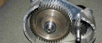
The clutch is located strictly between bevel gears, freely located on the main shaft.
This is how the reversing circuit in the gearbox is presented, which, if you look at it, is not too complicated. It only clings to the splines in the gears. This is what allows her to change the direction of the spiral-shaped gear. The cam, or fork, is represented by the clutch itself.
A reduction gearbox is a device that is designed to convert torque. There are worm, planetary and combined modifications. The engine with gearbox is capable of operating at high speeds. The standard model consists of a shaft, pushers and gear. If necessary, you can make a step-down device yourself.
Kinds
Depending on the type of transmission used in the gearbox, converters are divided into several types. Different devices are used in mechanisms of different fields of activity.
Chain
The name is due to the design of the gearbox, which is based on a chain as a transmitting element. There may be more than one in one device. The movement is provided by sprockets, the small one is the leading one, the big one is the driven one. The principle is similar to the system on a bicycle. Productivity and reliability depend significantly on the quality of materials used to manufacture the main driving parts.
Among the negative aspects, the need for regular maintenance should be highlighted: chain tightening, lubrication. Unlike a belt drive, a chain drive does not allow slipping and lasts longer.
With reverse
The reversing mechanism provides the equipment with the ability to reverse. In this case, the reverse rotation clutch is installed between the bevel gears, which are located on the main shaft.
Belt
The simplest gearbox available on the market is of the belt type. As a rule, budget gearbox models use just such a device. The belt serves as a transmission element that is attached to the pulleys. Under heavy loads, the belt slips or breaks.
Belt converters reduce the aggressive effect on the power plant, reducing jerking. In addition, their design is simple and repairs are easy.
Among the minuses, unfortunately, there are more factors.
- At high temperatures the belt stretches. This is what reduces grip.
- Rapid wear and tear.
- Belt drive rupture due to kinks or twists.
- As the speed increases, the belt begins to slip.
- The pulleys must be in the same plane.
Gear
Gear reducers are most often used in engines of heavy equipment. The transmission consists of a gearbox, differentials and regulator, gears and belts. The design of the device is simple.
A gear transmission contains bevel or spur gears. Due to the fact that several of them can be placed on one shaft at once, the dimensions of the converter are reduced.
Among the advantages, one can also highlight the quietness of the engine on this type of gearbox.
Worm
The worm gear inverter features long service life and high reliability. The design is considered not very complex and requires qualified maintenance. The worm gear is already angular. In addition, it has a reverse, which allows the equipment to move not only forward, but also backward.
The gearbox got its name from the presence of a special worm gear in its composition, which moves along a screw having a trapezoidal four- or two-start thread. By varying the number of teeth, you can change the rotational speed. All components are made of anti-friction steel, which is characterized by increased strength.
The converter consists of only two main components. In addition, it is quiet and smooth.
Angular
One of the most efficient and reliable gearboxes. Therefore, it is used to equip production machines and equipment operating under heavy loads. This type of converter is also actively used in the automotive industry.
The angular gearbox ensures the connection of the engine with the transmission, which is designed for chain drive
Please note that the magnitude of the load will depend on the quality of lubricants and temperature conditions
Downward
The goal of a reduction gearbox is to reduce the number of revolutions while increasing power. This is achieved by using a gear system. As a rule, modern converters of this type are equipped with an air cooling system.
Speed reduction gearbox
Topic Automatic gearboxes 5, 6-speed and DSG
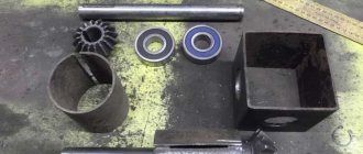
Its first element is the body, the location and interaction of all parts inside depends on it. Axes and shafts, gears, support bearings, sockets for them - this is its design. Cast iron or aluminum alloys are used for industrial designs. To assemble it yourself, you will either need an old frame, or you can weld it from steel. When welding, it is necessary to take into account that the metal is deformed and shrinks, so leave a little allowance for processing the main mounting sockets.
For the body, a 2-inch plumbing elbow is also used.
Gears are taken from old non-working chainsaws, pulleys from a washing machine.
There is another assembly option. No boring work is done, it is completely welded, and sections of pipes are taken as housings for the bearings. They are aligned as needed and then secured by welding and bolts.
The part at the top is made removable, and a hole is equipped at the bottom to drain the old oil.
The axle shafts are equipped with gears. Often, in a single-stage design, only the first ones are used, and the fit is carried out under tension, with pins, or a key. With this arrangement, the gears move with the shafts. The axis is used with an intermediate gear, which makes the direction of the shafts the same. It rotates freely along the axis with a minimum of clearance. They are protected from displacement to the sides by sides and washers. The shafts are made of 10-45 steel, with good machinability.
Bearings are supports. They take the entire load when moving inside the device. Functioning and efficiency depend on them. The closed type is suitable for a homemade device; they require minimal maintenance and are lubricated with lubricant. Their design depends on the forces encountered. If the device has spur gears, then single- or double-row simple ball gears are suitable. With a helical or worm mechanism, it is recommended to install roller, thrust-radial ones, since the load is greater.
Kinds
Depending on the type of transmission used in the gearbox, converters are divided into several types. Different devices are used in mechanisms of different fields of activity.
Chain
The name is due to the design of the gearbox, which is based on a chain as a transmitting element. There may be more than one in one device. The movement is provided by sprockets, the small one is the leading one, the big one is the driven one. The principle is similar to the system on a bicycle. Productivity and reliability depend significantly on the quality of materials used to manufacture the main driving parts.
Among the negative aspects, the need for regular maintenance should be highlighted: chain tightening, lubrication. Unlike a belt drive, a chain drive does not allow slipping and lasts longer.
With reverse
The reversing mechanism provides the equipment with the ability to reverse. In this case, the reverse rotation clutch is installed between the bevel gears, which are located on the main shaft.
Belt
The simplest gearbox available on the market is of the belt type. As a rule, budget gearbox models use just such a device. The belt serves as a transmission element that is attached to the pulleys. Under heavy loads, the belt slips or breaks.
Belt converters reduce the aggressive effect on the power plant, reducing jerking. In addition, their design is simple and repairs are easy.
Among the minuses, unfortunately, there are more factors.
- At high temperatures the belt stretches. This is what reduces grip.
- Rapid wear and tear.
- Belt drive rupture due to kinks or twists.
- As the speed increases, the belt begins to slip.
- The pulleys must be in the same plane.
Gear
Gear reducers are most often used in engines of heavy equipment. The transmission consists of a gearbox, differentials and regulator, gears and belts. The design of the device is simple.
A gear transmission contains bevel or spur gears. Due to the fact that several of them can be placed on one shaft at once, the dimensions of the converter are reduced.
Among the advantages, one can also highlight the quietness of the engine on this type of gearbox.
Worm
The worm gear inverter features long service life and high reliability. The design is considered not very complex and requires qualified maintenance. The worm gear is already angular. In addition, it has a reverse, which allows the equipment to move not only forward, but also backward.
The gearbox got its name from the presence of a special worm gear in its composition, which moves along a screw having a trapezoidal four- or two-start thread. By varying the number of teeth, you can change the rotational speed. All components are made of anti-friction steel, which is characterized by increased strength.
The converter consists of only two main components. In addition, it is quiet and smooth.
Angular
One of the most efficient and reliable gearboxes. Therefore, it is used to equip production machines and equipment operating under heavy loads. This type of converter is also actively used in the automotive industry.
The angular gearbox ensures the connection of the engine with the transmission, which is designed for chain drive
Please note that the magnitude of the load will depend on the quality of lubricants and temperature conditions
Downward
The goal of a reduction gearbox is to reduce the number of revolutions while increasing power. This is achieved by using a gear system. As a rule, modern converters of this type are equipped with an air cooling system.
Gearbox assembly recommendations
Replacing the cuff of the secondary shaft of the VAZ-2107 gearbox
Diagram of the gearbox of a walk-behind tractor.
The method of fastening the sprocket can be very diverse. Depending on the design of the shaft, the sprocket can be fixed to it using a key, a flange, or sometimes even fastening using spot welding.
The driven shaft of the gearbox can be assembled from two axle shafts. At the ends of the axle shafts, counter flanges must be machined. The second stage driven sprocket is inserted into its seat between the flanges, and the axle shafts are assembled into a single unit using a bolted connection.
If possible, you can do it a little easier without using axle shafts and bolts. To do this, the entire shaft is turned on a lathe. Fixation on the shaft will be carried out using a key or, if necessary, welding. A significant disadvantage of this method, compared to the previous one, is the less reliable and accurate fastening of the sprocket.
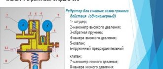
Diagram of the design and operation of the reducer: a - gas does not flow through the reducer, b - gas passes through the reducer, 1 - fitting, 2, 3 - pressure gauge, 4, 8 - springs, 5 - valve, 7 - membrane, 9 - screw, 10 - chamber, 11 - valve.
In order to protect against dirt and foreign objects getting into the chain drive, the second stage unit of the gearbox is placed in a protective housing. In addition to the function of protecting the transmission, the housing is a reservoir for lubricating fluid, which ensures smooth operation and reduces wear of rubbing parts.
The body of the housing must be provided with coaxial mounting sockets into which bearings are installed to support the shafts. To install the driven shaft, ball bearings in a conventional cylindrical housing are used. The drive shaft is mounted on bearings with an eccentric housing.
Due to the peculiarities of its design, the eccentric can change its position in the seat by an angle of up to 15°. Together with the bearing, the drive shaft will also change its position, thereby, if necessary, adjusting the amount of chain tension.
During operation, the teeth of the driven sprocket of the second stage of the gearbox are immersed in oil poured into the housing. The rotation of the mechanism ensures uniform distribution of the lubricating fluid among the chain drive units.
The tightness of the casing can be ensured by installing standard sealing gaskets and seals on the bearing seats and along the split line of the housing. It is quite easy to select bearing sealing gaskets, because... All sizes in this case are standardized and interconnected.
In the case of sealing the case, the situation is somewhat more complicated. If you use a non-standard product or housing from any old models, it is quite difficult to find gaskets. The solution may be to use specialized oil-resistant sealants.
With correct calculation and careful assembly of all the parts of a homemade walk-behind tractor, the unit will be in no way inferior to its factory counterparts.
Gearbox manufacturing process
First, the parameters of the power plant are calculated. The crankshaft speed can be found in the technical specifications.
This is the first quantity required to perform the calculation. The value is not constant, with the addition of “gas” the number of revolutions increases. Basic value: idle speed +10% .
Next, the suspension axle revolutions are calculated . Knowing the size of the wheels, it will be possible to calculate the amount of run-out per revolution. The number of axis revolutions is calculated to ensure a comfortable speed - 3-5 km/h, which is the second value for design.
For example, idle speed +10% is 600 rpm. The required wheel axle speed for 3 km/h is 200 rpm. So, the gear ratio should be 3:1 . The rotation speed of the axis is reduced by three times in relation to the speed of the motor shaft, and the torque increases accordingly by three times. Gearbox types:
- Gear - use the ratio of the number of teeth of the driven and driving gears. The device operates on the principle of steam in the gearbox. It doesn’t matter what shape the gears have - the teeth can be straight or oblique. A bevel gear is used when a walk-behind tractor requires an angular gearbox. It all depends on the location of the motor. If alignment is ensured between the motor shaft and the wheels, an angle is not required.
- A worm drive is needed to create a large gear ratio when there is a large difference between the revolutions of the drive axle and the engine. This design is more difficult to manufacture and maintain. The solution is optimal if the motor shaft is perpendicular to the wheel axis.
- Chain gearboxes work like a bicycle, but in reverse. The leading one is a smaller star. The reliability of the design is determined by the quality of the gear metal and the strength of the chain. A simple set from a bicycle may not withstand the load, so more durable ones are used - motorcycle ones.
- Belt devices are the simplest to manufacture. They are also the most unreliable and weak. Large torque is not transmitted, as the belts will slip. But the shock load on the engine is reduced - the design is more gentle on the drive shaft, jerks are smoothed out. Slippage is eliminated by installing a timing belt. In this case, you need to find a pair of toothed pulleys, for example, from an automobile timing system.
- Combined system. A device with a chain and gear drive can be manufactured in one housing, although the calculations in this case are more complex. But it is possible to transmit enormous torque with low engine power.
When choosing any design, do not forget about the following rules:
- do not allow distortions between the driven and driving parts;
- Bushings cannot be used, only bearings.
Any device other than a belt one must be constantly lubricated, therefore it must be in a box. The sealed housing will protect against dirt and dust, the ingress of which is inevitable during field work. Oil seals are installed on the shafts.
As an example, we can take factory products for Soviet agricultural machinery. The chain drive is not so sensitive to lubrication, but the chain must be cleaned and lubricated regularly .
Finalization of the finished design
You can choose a housing of a suitable size from a junkyard of old equipment, drill holes for the shafts on the bearings and assemble the device no worse than the factory one! Practice shows that selecting ready-made structures with minor modifications is much more effective.
An example for us will be a homemade unit based on the IZH motorcycle engine . A “native” gearbox with the ability to change speeds is used. The standard gear ratio is missing, but a small sprocket on the output shaft of the gearbox with a large sprocket from the drive wheel already provides a good reduction in the speed.
Another small sprocket is put on the shaft, which is installed in the bearing podium, which transmits torque to the wheels using a second chain. The drive axle, in turn, is equipped with a large diameter star. The result was a design with a 2-stage speed reduction and high torque.
Using a motorcycle gearbox , you can select the required speed without using the throttle. The engine almost always runs at idle speed, which extends its service life.
No less popular is the ready-made gearbox from the Ant scooter . There is no need to use the entire wheeled platform; installing your rollers on the bridge will suffice. By using the gearbox from the selected engine, you will get the optimal ratio of speed and power.
How to make a gearbox for a walk-behind tractor with your own hands
Diagnosis of gearbox faults
Two types of gearboxes, called worm gearboxes and chain gearboxes, have several small but quite important differences. They are contained in the characteristics that are inherent in the two types, but gearboxes operate with different factors: efficiency, angular speed, number of gears, as well as shafts, ratio between gears.
Gearboxes for walk-behind tractors, what are they?
When you have walk-behind tractors that are relatively cheap, they are often equipped with simplified assembly gearboxes that are not dismountable.
In this case, the service life is significantly reduced. Any additional possibilities are excluded, including: repair and, accordingly, assembly, replacement of parts, or disassembly to check the condition of the unit.
This means that the material from which the gearbox itself is made is of very low quality. Most of the parts presented in the assembly will not be sleeved. The gearbox diagram will allow you to present not only the principle of its operation, but also determine its service life.
Expensive walk-behind tractors have gearboxes with a more complex structure and the possibility of further assembly and disassembly. Maintenance can be carried out by correcting all problems in the operation of the gearbox. Repairs must be carried out in order to extend the service life of the operation.
It is important to replace faulty parts with other, more expensive elements. Lubricating the gearbox also extends its service life.
In most cases, the gearbox serves as a speed converter. That is, the angular velocity quickly and qualitatively goes to low. The input shaft will show a high angular velocity, but the output shaft will already be low.
Unforeseen breakdowns are prevented by constant and high-quality maintenance. With a stepwise variation in speed, the gearbox is called a conventional gearbox. In the case when it does not work according to a step system, it is called a variator.
Homemade bevel gear for walk-behind tractor
In principle, the gearbox does not have a very intricate structure; it is quite possible to assemble it yourself. First, make the correct calculation in rated power (Pn);Pn=Pe(hp)xFS. This will allow you to choose the correct angle to determine for the bevel gear. According to this principle, not only the number of possible revolutions in one minute will be calculated, but also the torque will be calculated.
A self-made gearbox needs to determine its operating conditions. Among them there is radial load, or axial load, which is present on the shafts at their ends. Its operation will be optimal if the temperature and type of lubricant are selected correctly.
After completing all the above steps, you can proceed to assembly. You can choose a factory case. The diameter of the housing will tell you what kind of housing the bearings for the shaft will have. A caliper and a good quality drill will help. Next, we take two bearings under the shaft itself.
It is important to install a steel flange on the front of the gearbox. Accordingly, inside: a bearing, necessarily flanged, and a washer. The flange is attached to the generator itself using screws
The steel key, together with the drive gear and driven gear shaft, must be selected in advance. All nodes connecting to the mechanism, which is a transmission, are connected to the rotary generator. It has a pulley that provides V-belt transmission. It should be secured to the driven shaft using a nut with a spring washer.
Types of gear units
The transmission of rotational motion from the motor shaft to the actuator shaft can be carried out by direct connection of the axes, if the speed and power of rotation of the engine are acceptable for operation, and the axes of the drive and driven shafts coincide. Such cases are extremely rare, and with several attachments for different purposes, direct transmission absolutely cannot be used. To match the speed and power of the drive and driven shafts, 4 types of mechanisms and their combinations are used. Main types of gears:
DIY gearbox
Despite the abundance of technical devices, many craftsmen undertake to make a gearbox for a walk-behind tractor with their own hands. This process does not require the use of smart factory machines. It is enough to have a standard set of tools: an angle grinder, welding fixtures, a drill and drills of different sizes, a screwdriver, and hammers. Among the parts for the converter itself, you should have shafts and bearings, sprockets with appropriately sized chains, gears and belts.
Preparation
The most important element in assembling a walk-behind tractor gearbox is preparation. Without preliminary calculations, determination of dimensions and the correct number of crankshaft revolutions, it will not be possible to successfully assemble the gearbox onto a walk-behind tractor.
Calculations are carried out in the following order:
- determining the engine crankshaft speed. This number cannot always be the same, since if you press the gas pedal, this number will undoubtedly increase. Therefore, to avoid errors and inaccuracies in further calculations, it is necessary to take the number of revolutions + 10%;
- the next stage is determining the number of revolutions of the suspension axis. We take the wheel size as a basis and use the formula to determine the amount of run-out per full revolution. Next, we design this for the normal speed of the walk-behind tractor - 3-5 km/h.
Assembly
If you have a strong desire, have the appropriate tools, and also have basic assembly and disassembly skills, you can assemble a gearbox for a walk-behind tractor of any modification. However, the lightest would be a chain gearbox. It is easy to assemble, reliable, and the materials for its manufacture are always available.
So, assembling a homemade gearbox for a walk-behind tractor occurs in the following way:
- The housing for the product can be an old gearbox, or you can weld the metal plates together with your own hands. The housing is the most important component because it protects the gearbox from mechanical damage, dirt, dust and other objects;
- a sprocket must be secured to the output shaft of the motor;
- then we attach the driven shaft to the sprocket, as before we attached it to the output shaft;
- if the shaft is formed from 2 axle shafts and the driven sprocket is fixed in the middle, the design will be more reliable. Next, secure everything with bolts;
- make holes in the protective housing for fastening and connect it to the main structure. It also holds liquid lubricant inside the mechanism;
- Use sealing gaskets around the edges of the housing.
This is interesting: the design of the carburetor of the Cascade walk-behind tractor.
If all of the above steps are performed correctly, then the gearbox for a walk-behind tractor, made by yourself, will work no worse, or even better, than the factory analogue.
Change of oil
An important element of unit care is maintaining a normal amount of oil in the gearbox. If you lose sight of this point, the remaining old oil can seriously damage the parts. If you notice oil leaks on the outside of the housing, rest assured that this is insufficient sealing or a problem with the gaskets.
It is better to use high-quality transmission oil for a walk-behind tractor.
Such data is usually described by manufacturers in the instructions for the mechanism.
General rules for changing oil:
- 25-50 hours from the start of operation of the mechanism - the first oil change;
- 100-250 hours from the start of operation or after 1-2 years of storage is the normal frequency of checking the oil.
How is the tilt and turn mechanism of a plastic window adjusted?
According to most users, a tilt-and-turn window is one of the most convenient to use, since they have the ability to open the sash in two planes: horizontal - the main one and vertical - in ventilation mode.
In order for a PVC window with a tilt-and-turn mechanism (TIM) to work reliably for the entire required period, it requires periodic maintenance and adjustment.
These mandatory operations are prescribed by the manufacturer and can be performed by the owner independently or with the involvement of a specialized organization. It is important, when making adjustments, to take into account that such structures, as a rule, have multi-season operating modes: winter and summer, which implies different settings of the trunnion positions.
When is tuning required?
The manufacturer of the structure clearly prescribes the frequency of adjustment of the scissors and awnings for each PVC window design.
Such actions must be carried out by the owner or contractor in the following cases :
- after completion of installation work when installing a new PVC window;
- after replacing the glass, which could lead to a failure in the fitting settings;
- every six months, when switching to “summer” or “winter” operating modes;
- if the sash begins to function poorly;
- if the window begins to blow out and is covered with condensation;
- The window sash does not open.
If the user discovers that the PVC window has begun to function poorly immediately after installation by the contractor, the problem cannot be corrected by adjustment, since in this case the source of the problem is considered to be poor-quality installation work. Therefore, the customer must immediately contact the installation company to correct malfunctions.
The latest swing-out models include the following structural components :
- group of loops;
- scissors;
- window handle;
- set providing angular transmission;
- constipation;
- a blocker that prevents incorrect opening;
- microlift;
- set of strike plates.
When operating a PVC window, experts distinguish between primary and current adjustment of a rotary-mechanical type.
Primary
The primary one is carried out after completion of installation and construction work when installing PVC windows.
During primary regulation, the POM is checked:
- completeness of opening/closing of the sash in horizontal and vertical positions;
- operation of the handle on the sash: when closing the window, the handle should be directed vertically downwards, when turning 90 degrees, the handle is moved horizontally, in this position the sash opens;
- turning to the top position - the sash opens vertically in ventilation mode;
- check the tightness of its clamping to the frame and the operation of the seals;
- check the operation of additional elements, for example, anti-burglary mechanisms.
When checking and adjusting all components and modes of the tilt and turn mechanism, you need to ensure that all manipulations are carried out without the use of effort - as smoothly and tightly as possible.
Current
Current POM regulation is carried out at least 2 times a year at the beginning of the warm and cold seasons. At this time, the mode of use of the unit is switched to winter and summer.
Before changing the operating mode of opening the sash, the entire fittings and insulation are thoroughly washed from dust and lubricated with silicone grease . After changing the position of the trunnions, check the tightness of the sash with maximum pressure for winter mode and minimum for summer mode and, if necessary, make adjustments.
What exactly needs to be regulated?
Before making adjustments to the POM, you need to know its design. This mechanism is divided into 2 parts: the upper one, which the craftsmen call “Scissors” and the lower one, which is responsible for the upper movement of the sash. The upper adjustment occurs with a slight shift to the left and right, and the lower adjustment is adjusted by shifting up and down.
The balancing process begins with the upper part of the POM, then adjusts the lower part. To do this, you will need to open the sash, find the upper part of the mechanism and there is a small adjustment hole on it that fits a hex key.
In certain cases, adjusting the POM is not able to solve the problem of a poorly functioning sash, since the failure may be caused by a defect in the mechanism itself. In this case, you need to invite specialists who installed such a block, especially if the window is still under warranty.
What tools are needed?
To adjust the POM, the contractor will need to have a standard set for adjusting PVC windows , which includes:
- electric screwdriver for working with screw connections;
- bits for a screwdriver;
- pliers;
- hex key No. 4, which is used directly for the adjustment operation; it can be purchased at any furniture store, since it is used for assembling furniture;
- two screwdrivers - flat and Phillips, for adjusting some components of the tilt-and-turn mechanism;
- silicone grease for fittings.
Step-by-step instructions for setting it up yourself
After the performer carefully inspects the external condition of the rotating mechanism, cleans it of dust and lubricates it with silicone grease, they begin the adjustment process :
- Adjustment starts from the top.
- Open the sash, inspect the mechanism, find a small adjustment hole suitable for a 4 mm hex key.
- Insert the adjusting key into the hole, unscrew the bolt secured there, completely freeing the upper part of the mechanism.
- Find a small aluminum strip to which the window is attached to the mechanism, and fix it in a slightly different position to the side or lower if the window, for example, rubs from above.
- Make sure that the adjustment is correct, lightly cover the sash and make sure that it fits into the frame as evenly and easily as possible.
- The mechanism is attached to the window in the reverse order.
- Make sure that the window is aligned correctly, the final adjustment can only be made using the lower adjustment, it is important not to overdo it with the adjustment by moving the rail too far.
- Move to the bottom of the mechanism.
- On the lower mechanism, the protective coating in the form of a cap is removed by ordinary removal.
- They find a specially made turnkey tube.
- The key is lowered into the tube with the long side and gradually begins to unscrew.
- Next, the setting process is similar to the upper mechanism.
Differences in technology for the rotary mechanism
Such differences, when making adjustments, are associated with the different design of the mechanisms of PVC windows; in the rotary version, hinges are installed on the sash. The adjustment process is aimed at adjusting the elements of the window structure, which are responsible for the vertical position of the sash.
Start balancing from the bottom loop . Perhaps it weakened during use or was over-tightened during the autumn-winter cold period. In the case when the hinge is very slack, the sash is lifted up, and in the case when it is pressed strongly, the hinge must be loosened.
During the adjustment process, the sash should be level, the process should take place with the window closed.
Possible errors and difficulties
The process of adjusting the POM window is not complicated; all home craftsmen can do it, if they have the necessary tools and consumables.
However, in practice, performers often make mistakes that can have very negative consequences, which can disrupt the overall setup of the fittings, as a result of which the window sash will not open.
The most common mistakes when performing regulatory measures include:
- Wrong choice of setting area, start balancing from the bottom of the tilt and turn mechanism, and it is necessary - from the top.
- The preset cleaning of the mechanism from dust and dirt and lubrication for smooth operation of the elements have not been carried out.
- Strong extension of the aluminum sash strip.
- The process of general adjustment of the operation of the fittings in the adjustment field has not been completed.
How much does the service cost?
Despite the fact that the process of adjusting the tilt-and-turn mechanism of a window sash is not complicated, many owners, especially of expensive window units, prefer to invite specialists for this work. Often such balancing is carried out as part of other operations, for example, when preparing a window for operation in a certain season of the year.
The cost of services for such work depends on the window model, modification of the installed tilt-and-turn mechanism and the area where services are provided; in Moscow and St. Petersburg these prices are usually 15-20% higher.
Prices for certain types of work on setting up POM windows:
- Profile cleaning - 250 rub. per p.m.
- Sealing - 500 rub.
- Adjusting the opening sash - 350 rubles.
- Adjustment of the swing-out flap - 850 rubles.
- Replacement of POM - 1230 rub.
- Replacement of seals with labor and material - 150 rub./l.m.
- Lubricating window fittings - 300 rubles.
- Binding accessories - 1800 rub.
- Repair work on the folding mechanism - 1260 rubles.
- Repair work on fittings - from 1400 rubles.
- Visit of a specialist - from 300 rubles.
Conclusion
A comprehensive PVC window system, which can operate both by opening and tilting for ventilation, is today considered the most effective and is preferable when choosing a design.
In order for the tilt-and-turn mechanisms to work accurately and the window to perform its energy-efficient functions, adjustment operations must be carried out periodically - the first when installing the window unit, and the current ones 2 times a year, before the start of the summer and winter climatic seasons.
Purpose and types of gearboxes
Diagram of the angular gearbox of the walk-behind tractor: 1 - retaining ring, 2 - adjusting ring, 3 - bevel gear, 4 - adjusting rings, 5 - bearing, 6 - intermediate gear shaft, 7 - upper housing, 8 - output shaft, 9 - adjusting rings , 10 — bearing, 11 — bevel gear, 12 — retaining ring, 13 — boot cup, 14 — boot, 15 — cuff, 16 — adjusting rings, 17 — lower housing, 18 — adjusting shim, 19 — bearing, 21 — cover , 22 - gear, 23 - gear, 24 - shaft.
An important element of the walk-behind tractor design is the gearbox. It transmits torque from the engine shaft to the working tool or wheels of the unit, depending on the design. Thanks to the features of the device, torque is not simply transmitted, but is amplified with a simultaneous reduction in the number of revolutions of the driven shaft.
According to their design, gearboxes can be of several types:
- Geared. The gearbox consists of shafts with cylindrical and bevel gears mounted on them. By design, gear reducers can be implemented in a straight pattern (torque is transmitted through a spur gear) or angular (a bevel gear is used to transmit torque from the driven shaft directly to the gearbox).
- Gear-worm. Used with a vertical engine crankshaft. The gearbox consists of a worm gear and a worm (a metal screw with a large-pitch rectangular thread). A special feature of this gearbox is the transmission of rotation at an angle of 90°.
- Chain. Torque from the engine to the gearbox shafts is transmitted by a metal chain that rotates the sprockets.
- Belt. It is analogous to the chain method with the only difference that instead of a chain, a V-belt or rectangular belt is used, and instead of sprockets, pulleys with profile grooves are used to hold the belt.
The design of a motor cultivator often uses angular gear-worm or chain gearboxes. Gear reducers are used in the designs of powerful units. The belt transmission method is quite rare, because It is believed that the belts are prone to breaking and slipping from their seats.
Angular reducer
In accordance with the specified purpose, the rotor, in its design, is an angular gearbox that converts rotation around a horizontal axis into rotation around a vertical axis. In relation to the purpose and regardless of the design, dimensions and parameters, the rotors have a fixed housing in which a rotary table is mounted on bearings, rotated by a horizontal drive roller through a bevel gear. The rotary table clamps the drive pipe, which transmits torque to the drilling tool. In this case, the design of the rotor clamps allows the drive pipe to move freely in the axial direction. Below is information about the design and operational and technical parameters of rotors of various sizes.
In the LiAZ-677 bus, due to the location of the steering control, an angular gearbox consisting of a pair of bevel gears was introduced into the latter. The drive gear is mounted on the steering shaft, and the driven gear is mounted on a shaft connected to the steering driveshaft. The shafts of the drive and driven gears rotate on tapered roller bearings located in the bevel gear housing.
The rotation of the rotator is carried out by alternately engaging the upper and lower bevel gears on the vertical shaft of the angular gearbox 18 using a gear coupling. When the mast is lowered, this clutch is automatically disengaged by a fork interlocked with the right mast mounting clamp. The housing of the upper gearbox 9 has the ability to rotate around the axis of the triangular vertical shaft D of the rotator drive.
Rotation of the wheel from the electric motor 12 through the intermediate shaft 13 is transmitted using the vertical shaft of the angular gearbox 14, which is also the support of the wheel.
In a KamAZ vehicle, torque is transmitted from the steering shaft to the steering gear shaft through an angular gearbox and a cardan drive.
The contactor delivery kit includes the following components: contactor housing, propeller pump, cooler, bevel gearbox, parallel gearbox, drive frame and steam turbine.
The rotor block includes a B2-300 engine, an angular mating gearbox, a gearbox, an angular gearbox for driving a winch, a drilling winch, a friction clutch, a rotor, a telescopic tower with a crown block, a traveling block with a hook and a swivel.
An axial fan consists of a wheel, on the hub of which eight rotating blades are attached to j; an angular gearbox that serves as a support for the wheel; two-speed electric motor and aerodynamic elements.
In the case of overhauling the control valve, it is necessary to ensure that the recess at the end of the spool is facing the angle reducer, and the chamfers on the reaction plungers of the check and safety valves are facing outward. The spool, reaction plungers and valves must move smoothly in the control valve body without jamming.
The pump propeller is mounted on the upper end of a vertical shaft, passed down through a mechanical seal and connected at the lower end by means of a coupling with an angular gearbox.
At the front end of the diesel engine there is a fan 33 of the traction electric motors of the rear bogie, the fan wheel of which is driven into rotation from the output shaft of the diesel engine through an angular gearbox.
When assembling the gearbox, special care is required to press in the bearings and adjust the gearing, carried out by selecting the thickness of the set of shims installed between the drive gear housing and the bevel gear housing.
The drive of the winch, as mentioned above, is carried out from the car engine through the 8AG power take-off (on ZIS-5 and ZIS-150 cars) and a special karlanpyn shaft and angular gearbox for the winch transmission.
The general assembly of the steering mechanism is carried out on a special stand from assembled components: a screw with a ball nut and a piston rack, a control valve, a steering bipod shaft, covers and an angular gearbox.
| Pressure for valve adjustment. |
Basic elements of a mechanical system
To support the main elements, the gearbox (speed reducer) is provided with a system of shafts and axles. Single-stage designs use shafts with rigidly seated driven and driving gears. Rigidity of fit is achieved through the use of keys or splines. Lateral displacements are adjusted with special nuts that press gears or sprockets against thrust collars. The material used is structural steel. It is perfect for making a creeper for a walk-behind tractor or cultivator.
Bearing units are supports for steel axles and creeper shafts on a walk-behind tractor. Bearings bear the main load during operation of the power unit.
Whether the speed reducer for a motor cultivator will work normally depends on the correctness and quality of the bearings. For homemade designs, bearings with closed cages (closed type) are better suited. This will save you from having to regularly change the lubricant. The type of gearbox bearings depends on the type of loads taken. Support bearings are installed on a creeper for a walk-behind tractor with straight gears, and thrust bearings are installed on gears with an oblique tooth profile and worm shafts. They are usually subject to longitudinal axial forces from an electric motor or internal combustion engine.
The gears and sprockets in the gearbox determine the speed and nominal rotation speed of the output shaft. For their production, special equipment and equipment are used. It is better not to make the creeper gears for a walk-behind tractor with your own hands. Buy ready-made gearing in specialized stores.
Whether the speed reducer for a walk-behind tractor will normally accept dynamic loads from the power unit depends on the correct selection of geometric dimensions and gear ratio. When installing gears, all necessary clearances must be maintained. To do this, carefully study the drawings. Clearances directly affect the ability to absorb significant loads from an internal combustion engine or electric motor.
The step-up and step-down gearbox for a minitractor is lubricated with I-20 industrial oil. The oil level is determined taking into account the operating conditions of the unit. Oil seals are used to prevent leaks.
Mechanism elements
Do-it-yourself reduction gearbox for a walk-behind tractor
Regardless of whether a purchased or homemade reduction gearbox will be used in a walk-behind tractor, you need to understand how the elements of the mechanism are located, how to maintain and repair them. Reduction gearboxes for walk-behind tractors can be of several types, each of which has its own advantages and disadvantages.
Scheme for connecting the speed reducer to the gearbox
Gear reducer
As a rule, it consists of one or two stages; The main elements are gears. This type is one of the most reliable mechanisms used in creepers. Used in the most powerful walk-behind tractors. Its advantages may include:
- durability;
- reliability;
- small dimensions;
- possibility of reverse.
Such creepers are not without their drawbacks, the main ones being maintainability and price. In case of breakdown, as a rule, they are replaced entirely, which requires significant financial costs. In addition, it is necessary to monitor the presence of lubricant, the absence of which can lead to rapid wear.
Worm gear
The main element is the worm gear. Allows you to reduce the dimensions of the walk-behind tractor and improve weight distribution due to the perpendicular arrangement of the drive shafts and wheels. Most often they are installed on light and low-power walk-behind tractors.
- large gear ratio;
- small dimensions;
- light weight.
The main disadvantage of a worm gearbox is the lack of reverse. In addition, in the event of a breakdown, the stroke reducer is completely replaced.
Chain reducer
One of the most popular types of gearboxes among users. Most often they are made dismountable, which simplifies maintenance and diagnostics. The most common failure is a broken or stretched chain, shearing of sprocket teeth or drive shaft keys. All these breakdowns, as a rule, are quite easy to fix yourself by replacing the failed part.
The advantages of stroke reducers of this type include:
- simplicity;
- reliability;
- possibility of reverse;
- maintainability.
Combined gearbox
Gearboxes of this type are characterized by the presence of different types of gears in one mechanism: gear-chain or worm-chain. The need for such stroke reducers is dictated by the fact that in gear and worm gearboxes the center distance between the drive and driven shafts is regulated by the size of the gear and directly depends on the engagement module and the number of teeth. In a chain drive, the distance between the shafts can be adjusted by removing or adding links.
When assembling the design of a walk-behind tractor, it is not always possible to place all the units in an ideal position, and the need for an intermediate transmission link arises. This function is successfully performed by a chain drive, which compensates for the distance from the gear or worm gear to the wheel or drive shaft.
What does the speed reducer consist of?
Depending on the type of reduction gearbox, a homemade creeper consists of the following main parts: input (high-speed) shaft, output (low-speed) shaft, worm and worm wheel, drive and driven gears or sprockets.
In this case, the driving sprockets and gears always have a larger number of teeth than the driven ones. Auxiliary elements can be various couplings, bearings, and keys. In gear and worm gearboxes there is always a housing, which cannot be said about chain gearboxes. They may either completely lack a case or cover only part of the mechanism.
Stages of work to create this device
- Installation of drive sprockets on the input shaft. In this case, installation can be done by spot welding, flange or key connection;
- Assembly of driven shaft axles;
- Installation of the driven sprocket;
- The case can be picked up from disassembly and adjusted or made by yourself. At the same time, it is necessary to make technological holes in it for oil seals and bearing connections;
- Installation of closed type ball bearings. An excellent option would be cylindrical ones. Their installation is carried out by tension;
- The drive shaft is mounted on eccentric bearing supports with the ability to adjust the chain tension by at least 15 degrees;
- At the final stage, a lid with a sealing gasket is installed.
Having decided to do this, it is better to first assess your strengths, knowledge and skills in handling the tool, so as not to get into trouble by spending a decent amount of money, a lot of time and effort, and at the same time, without creating the necessary device, but if you are an existing or former mechanic, you can safely get down to business.
The most important part of the walk-behind tractor is the drive. It is the main one of all the elements presented in the walk-behind tractor. Therefore, when there is a need to purchase a gearbox, all its further operation, and even the functionality of the walk-behind tractor, depends on the quality.
A gearbox for a walk-behind tractor is a certain type of device capable of transmitting and appropriately converting torque, for which mechanical transmissions are conductors. Accordingly, agricultural machinery will work more productively.
Diagram of a gearbox assembled from parts of a decommissioned car
This gearbox is assembled from parts of the main drive of the GAZ-69 vehicle. The bevel gears rotate from the drive sprocket, which is mounted on the shank. The torque is then redirected to one of the two driven gears, which rotate in bearings numbered 206 on the spline shaft. At the right time, the gear that engages with the reverse sleeve on the central spline of the shaft works. Then the cardan transmits the movement to the differential or the drive wheel of a mechanical vehicle.
Read also: Heating concrete with electrodes connection diagram
And the final important point for owners of walk-behind tractors or mini tractors. When purchasing a mechanism, price also plays an important role, because cheap units are mostly equipped with non-separable gearboxes. Such mechanisms are unreliable for long-term operation. If necessary, this gearbox cannot be repaired, disassembled or reassembled, or parts replaced. It is made of low quality metal, its parts are not gelled.
Expensive units are equipped with gearboxes that can be disassembled, which allows for gearbox maintenance and repairs. Like any other mechanical vehicle, it needs constant rechecking, repair, and updating, and the gearbox must be constantly inspected and monitored. From time to time it is necessary to carry out diagnostics of the mechanism to prevent breakdowns in the future.
When purchasing, it is more profitable to buy a more expensive gearbox, because it will serve you longer.
The pride of many summer residents is a homemade walk-behind tractor, assembled with their own hands from parts that have served their age. Installing an electric motor or a small gasoline motor from an old scooter or motorcycle onto a frame with wheels is not difficult even for a novice amateur mechanic. But what you have to think about is the gearbox for the walk-behind tractor.
Main types, their purpose
In the household, walk-behind tractors and cultivators are most often used. According to their design features, they can be installed:
- Gear mechanism. Bevel or cylindrical gears are pressed onto the drive shafts. This design allows them to be used in direct transmission of rotation from the engine. Can be used as an angular gearbox for a walk-behind tractor, while the design uses a bevel gear.
- The device is gear-worm. Most often installed with a vertical engine crankshaft. A gear with a certain number of teeth and a worm screw with a certain thread pitch is a schematic description of the type of device. The main feature is the transmission of rotation of the engine shaft at a right angle.
- Chain device. The shafts are equipped with toothed sprockets. They are wearing a special chain, with the help of which torque is transmitted from the motor. For good performance, the chain is tensioned using a tensioner roller.
- Belt device. Rotation is transmitted using belts. Pulleys with grooves for belts are pressed onto the shafts, and the belt is tensioned using a tension screw.
Most often, in equipping the angular gearbox of a boat motor, walk-behind tractors and other mechanisms, a chain, gear or gear-worm gear is used. Previously, the main one was the belt system; due to breaks, the belt slipping off the pulleys, its operation was considered unreliable.
https://youtube.com/watch?v=zjBReRfGM3g
https://youtube.com/watch?v=zjBReRfGM3g
Types of mechanisms
According to the method of operation and action, all transforming mechanisms for walk-behind tractors are divided into several types:
- angular;
- downward;
- reverse with reverse speed (reverse gearbox);
To redirect rotational energy from a vertical drive to a horizontal plane, an angular gearbox using bevel gears (bevel gearbox) is used.
Reducing the number of revolutions and increasing the power of the drive mechanism is provided by reduction gearboxes, or creepers for the walk-behind tractor. They are considered the most reliable for operating a diesel or gasoline air-cooled walk-behind tractor. This allows them to be used for particularly difficult work - for example, plowing heavy soil or harvesting potatoes using a potato digger.
Preparatory work
Motoblock device.
When making a homemade walk-behind tractor, before starting to manufacture the gearbox, it is necessary to make at least an approximate calculation of it.
Based on the calculation data, we can estimate:
- gear ratio;
- gearbox type;
- torque values;
- the magnitude of the loads on the shafts;
- overall dimensions of transmission mechanisms (depending on the type of gearbox selected).
You can make a homemade walk-behind tractor with a gearbox that works on different principles. However, gearboxes with chain drives are most often used in home-made units. This is due to a compromise between the availability of component materials, the reliability of their operation and the relative ease of assembly.
For production you will need:
- sprockets with a pre-calculated number of teeth, providing the required gear ratio;
- driven shaft;
- bearings of the required size for installing the drive and driven shafts;
- chains of the required length;
- metal corners for attaching the protective housing;
- protective housing (crankcase).
Types of gear units
The transmission of rotational motion from the motor shaft to the actuator shaft can be carried out by direct connection of the axes, if the speed and power of rotation of the engine are acceptable for operation, and the axes of the drive and driven shafts coincide. Such cases are extremely rare, and with several attachments for different purposes, direct transmission absolutely cannot be used. To match the speed and power of the drive and driven shafts, 4 types of mechanisms and their combinations are used. Main types of gears:
The worm gear is structurally limited by the speed-reducing function; the rest can be used in both downshifts and overdrives. In addition, such a gearbox always has a driven axis perpendicular to the drive shaft. This scheme is called an angular gearbox. In addition to the worm gear, you can change the direction of the axis using a spatial planetary mechanism. Belt and chain drives keep the driven axis parallel to the engine axis. In simple devices, reverse is possible only when the rotation of the engine changes.
Motoblocks use engines with a high number of revolutions per minute, which can be verified in the product data sheet. This means that you need to make a gearbox with your own hands to reduce the speed, and it is better to choose what type of homemade gearbox for a walk-behind tractor, knowing the characteristics of each type.
How to make a reduction gearbox
One of the main and critical parts of a reduction gearbox is its housing. The relative position of the axes and shafts, the gaps between the gears and the alignment of the sockets for the support bearings depend on how correctly it is designed and manufactured. In industrial gearboxes, almost all housings are made by casting from cast iron or aluminum alloys, but at home it is practically possible to do this unreal. Therefore, it would be best to either select and modify a ready-made housing to suit your needs, or make it welded from sheet steel. However, in this case, you need to remember that during welding the metal can “lead”, and in order to maintain the alignment of the shafts, it is necessary to leave an allowance for the final processing of the bearing seats. Some craftsmen act differently - in order not to suffer from boring work, they weld the body completely, and use sections of pipe as seats for bearings, which are set in the desired position and only then finally secured in place with bolts or welding. In order to facilitate the maintenance of the gearbox, it is recommended to make the top cover of the housing removable, and provide a drain hole at the bottom to drain the used oil;
The shafts and axles of the gearbox serve as supports for the gears. As a rule, in a single-stage gearbox only shafts with rigidly mounted gears are used (pressure fit, keyed or splined). That is, both gears rotate together with their shafts. The axis is used when we need to insert an intermediate gear into the gearbox (for example, to ensure the same direction of rotation of the input and output shafts). Such a gear rotates freely with minimal clearance on its axis, and from displacement to the side it is fixed either by a thrust collar and a nut, or by locking split washers. It is recommended to use steel 10...45 as a material for shafts, which has sufficient strength and is easy to machine;
The bearings in the gearbox serve as supports for the shafts and absorb the loads that arise during operation of the gearbox. The performance and reliability of the gearbox as a whole depends on how correctly the bearings are selected. For a homemade gearbox, it is better to choose closed-type bearings, which are lubricated with grease and require a minimum of maintenance. The type of bearings depends on the type of load taken. If spur gears are used, conventional single or double row ball bearings will be sufficient. If the gearbox has helical gears or a worm gear, then an axial load is transmitted to the shaft (and, accordingly, the bearings). In this case, you will have to provide a roller or ball angular contact bearing;
No less important parts of the gearbox are the gears. It is with the help of gearing that we change the speed of rotation of the output shaft. To manufacture gears, special metal-cutting equipment is required, so it will be economically feasible to use ready-made parts from decommissioned units. It is the geometric dimensions of the gears and their gear ratio that will determine the interaxal distance between the gearbox shafts, as well as the layout of its housing
When installing gears, it is important to correctly set the gap between them, since the load capacity and noise level during operation of the gearbox depend on this. Liquid industrial oil of grade I-20 is well suited for lubricating gears, which is poured to such a level as to cover the teeth of the lower gear.
The remaining parts will be lubricated by spraying oil throughout the internal cavity of the gearbox;
Shaft seals are needed to prevent oil from leaking out of the gearbox. They are installed at the shaft outputs and are usually secured in bearing caps;
Safety coupling. In order to avoid emergency destruction of gearbox parts from excessive load, a so-called safety clutch is usually used. It can be in the form of a shear pin, spring-loaded friction discs or a bellows and is selected locally;
Bearing caps. These parts greatly facilitate the installation and maintenance of bearing units and can be blind or through. You can select them from ready-made parts or turn them on a lathe.
Do-it-yourself winch with manual or electric drive
Helical gearbox: overview of types and operating principle
The drill body already contains a planetary gearbox of approximately 3:1. A very powerful machine. Do it yourself - with your own hands" - a site of interesting homemade products made from scrap materials and items at home.
Today there are different types of devices on sale, but many car owners make a winch with their own hands. It is impossible to make a winch without a gearbox. Motorists use the most unusual gearboxes, for example, a trolleybus door opening mechanism.
When choosing a starter, preference should be given to models with a planetary gearbox. Each master develops and implements his own designs. The winch can be made by hand using the following technology. After installing the drum, a gearbox is attached to its axis. An adapter necessary for mounting the starter is installed in the upper part of the gearbox.
For installation, you first need to place the winch at the mounting location and make markings. If the car gets stuck deeply, you can attach a winch and pull the car out of the quagmire.
Anyone who can confidently work with a welding machine, an angle grinder, and, if necessary, can even use a lathe, can make interesting homemade products from a chainsaw with their own hands. This chainsaw moped is equipped with a gearbox with a gear ratio of 18:1 and a CVT transmission, which allows you to comfortably move on it at the speed of a regular bicycle.
Since the ice auger operates at low speeds, to adapt the chainsaw motor, it is connected to the auger through a reduction worm gear. It consists of a frame, an engine with a gear reducer, a control panel, a generator and connecting electrical cables. Detail 2.JPG please help, the differential housing rotates, which rotates two satellites, one of which transmits rotation to the engine, and the second satellite is connected to a worm gear.
If the gearbox has helical gears or a worm gear, then an axial load is transmitted to the shaft (and, accordingly, the bearings). Sometimes there is also distortion of the walls in a two-stage gearbox. Sometimes a purchased, working gearbox installed on a model suddenly fails, and an attempt to turn its shaft by hand often leads nowhere.
It may seem that a gearbox for a walk-behind tractor is a complex technical device and can only be manufactured in a factory setting. However, many of our farmers have homemade gearboxes for walk-behind tractors. The most important part of the unit is the drive. When there is a need to buy a gearbox, you need to know that its further operation and even functionality depends on the quality of this particular unit.
The gearbox transmits and appropriately converts torque, the conductors of which are mechanical transmissions. You can literally make a device from junk items, you just need to understand the principle of how the design works.
Assembling a homemade cultivator
Its power is 1.4 liters. With. It is also suitable for use as a cultivator unit.
One of the most important stages of work is connecting the base with cutters to the trimmer.
This operation is greatly simplified if the end of the shaft has a reverse thread, to which the equipment is simply screwed. The DDE GB 32 RD trimmer is just such a model.
In such a case, a nut of the required diameter is welded onto the steel tube. There are also trimmers that have threads inside the shaft.
How to make a cultivator from a drill with your own hands
If you need to perform work in the garden with a cultivator, but this must be done with great precision, you can make the tool in question from a conventional drill. To do this you will need very little:
- working drill;
- a steel rod that can compress the chuck of an existing drill;
- cutters.
You also need to have a tool for processing metal surfaces:
- Bulgarian;
- emery;
- welding.
Preliminary drawing up of drawings for a cultivator made by yourself is not required.
A steel rod, the optimal diameter of which is 10 mm, will act as a shaft that transmits rotation from the drill motor through the chuck to the cutters.
Any sheet metal can be used as a milling cutter if its thickness and hardness allow working with problematic soils.
You can also use ordinary metal corners, which are 10 mm wide and 100-150 mm long. Using a grinder, ordinary flat rectangles are made from them.
Then they bend at an angle of 90 degrees. The cutters are sharpened on both sides and welded to a steel rod using electric or gas welding.
After this, you can safely insert the resulting structure into the drill chuck and carry out work on cultivating your garden or garden plot.
How to choose?
You can make a converter for a walk-behind tractor with your own hands, but if you do not have the necessary experience, it is better to purchase it at specialized retail outlets. Today, the market offers a huge range of high-quality modifications, the cost of which varies depending on various technical and quality characteristics.
The following factors may affect the price.
- The quality of the materials from which the components are made.
- The number of functions performed by the converter.
- Manufacturer status.
- Reversing mechanism (its presence or absence).
- Reproducible power. When choosing, you should not chase more power, but focus on the technical characteristics of the vehicle. Because the capabilities of the gearbox and the engine must match.
- Type of construction (collapsible or non-collapsible).
- Design features. For example, the type of transmission or type of clutch.
- Life time. As practice shows, a properly selected converter can last from 7 to 15 years, depending on the type of transmission.
When purchasing a converter, do not forget about the dimensions of the motor. It will be a shame to spend money on something that will not fit into the case. When choosing a gearbox, you must also take care of the oil that is poured into it. It plays an important role, being the key to efficient and uninterrupted operation of the mechanism.
There are several factors to consider when choosing.
- Climatic conditions. If the vehicle will be used in northern regions, then give preference to those products that do not freeze at sub-zero temperatures. In the southern regions you should not spend money on purchasing such options.
- Loads. If there is heavy or virgin soil, the walk-behind tractor will operate under increased loads, which means the friction between the parts will increase and the torque will increase. To increase the service life of spare parts, you should select a lubricant that takes these features into account.
When choosing a gearbox from a specific manufacturer, remember that during repairs it is necessary to replace failed components with similar ones. Therefore, you should choose a supplier who has offices in your region.
Motoblock gearbox design
Like any other mechanism of a walk-behind tractor, the gearbox of an agricultural implement consists of certain elements. Taking into account the type of gearbox, its design can be equipped with certain parts. Basically, the gearbox design in detail looks like this:
- Cover and pulley;
- Bearings;
- Bushings on the input shaft;
- Adjustment and shift lever;
- Shift fork and shaft;
- Gear in the intermediate shaft;
- Shaft block;
- Double-row chain;
- Sprocket block;
- Washers and seals;
- Input shaft;
- Right and left axle shafts;
- Double star;
- Clutch;
- Bracket and spring;
- Clutch fork.
The mechanism diagram below will tell you in more detail how the walk-behind tractor gearbox works. Despite the rather complex design of the mechanism, its dismantling and reassembly will not raise any questions even for a beginner. To do this you need:
- Completely remove the gearbox from the walk-behind tractor;
- Unscrew the screws and remove the protective covers;
- Carefully remove the bushing on the input shaft, dismantle the lever and fork that switches the mechanism;
- Remove the input shaft and gear from it;
- Remove the shaft bushings and chain;
- Dismantle the shaft block and remove the sprockets from it;
- Remove the intermediate shaft along with the gears;
- Remove the clutch, left and right axle shafts.
After completing all of the above steps, you will receive a disassembled walk-behind tractor gearbox. After repair, the mechanism must be reassembled in reverse order.
Types of gearboxes
The design of any converting device for a walk-behind tractor (gearbox) consists of a set of motion-transmitting shafts or gears of different diameters, enclosed in a durable housing.
Converting devices are divided into several types according to the type of transmission:
- chain;
- belt;
- gear;
- worm (gear-worm);
- combined systems.
For chain-type gearboxes, rotation transmission is provided using a chain and sprockets of different sizes, which are installed on rotary shafts. The operating principle of a belt mechanism is similar to a chain mechanism, but instead of sprockets and a chain, pulleys and a belt are used.
Inside the housing of the gear reducer there are shafts with gears mounted on them, having straight or oblique teeth. Gears transmit rotation from the engine to moving parts. Bevel gears are used in angular mechanisms for heavy walk-behind tractors.