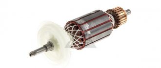
DIY mini gearboxes for electric motors
Owners of home workshops have many devices and devices that greatly facilitate manual labor and increase work efficiency. One such mechanism is a reduction gearbox.
It is mainly used to change the rotation speed of the output shaft downward or increase the torque on it. By its design, this device can be combined, worm or gear, as well as single- and multi-stage.
Many people make a reduction gearbox with their own hands.
How to make a gearbox with your own hands
How to make daytime running lights with your own hands
I think there is no particular need to talk about the benefits of the gearbox. Everyone already understands everything perfectly well. With its help, you can change the speed of the engine shaft or change the amount of torque.
The article describes in detail how and from what you can make a gearbox with your own hands.
The articles How to make a pulley with your own hands and Educational program Belt drive will help you understand the material presented below in more detail.
Location: Simferopol
Subject of the E+M channel: Manufacturing of mechanisms and electronic devices from improvised means, at minimal cost! The channel presents lessons on physics, mechanics and electronics, which will be needed for independent construction and understanding of the operating principle of homemade devices.
- bicycle spoke
- bushing engine
- wooden slats
- tin
- CD boxes
- linoleum
- sheet plastic
- rubber band for money
- Super glue
- hot melt adhesive
- screwdriver;
- telescopic antenna;
- square;
- compass;
- awl;
What is a gearbox?
This mechanism is a transmission link that is located between the rotational devices of an electric motor or internal combustion engine to the final operating unit.
The main characterizing indicators of the gearbox are:
- transmitted power;
- efficiency;
- number of driving and driven rotary shafts.
Gear or worm gears are fixedly attached to the rotational devices of this mechanism , which transmit and regulate movement from one to another. The housing has holes with bearings on which the shafts are located.
Angular reducer
In accordance with the specified purpose, the rotor, in its design, is an angular gearbox that converts rotation around a horizontal axis into rotation around a vertical axis.
In relation to the purpose and regardless of the design, dimensions and parameters, the rotors have a fixed housing in which a rotary table is mounted on bearings, rotated by a horizontal drive roller through a bevel gear. The rotary table clamps the drive pipe, which transmits torque to the drilling tool.
In this case, the design of the rotor clamps allows the drive pipe to move freely in the axial direction. Below is information about the design and operational and technical parameters of rotors of various sizes.
In the LiAZ-677 bus, due to the location of the steering control, an angular gearbox consisting of a pair of bevel gears was introduced into the latter. The drive gear is mounted on the steering shaft, and the driven gear is mounted on a shaft connected to the steering driveshaft. The shafts of the drive and driven gears rotate on tapered roller bearings located in the bevel gear housing.
The rotation of the rotator is carried out by alternately engaging the upper and lower bevel gears on the vertical shaft of the angular gearbox 18 using a gear coupling.
When the mast is lowered, this clutch is automatically disengaged by a fork interlocked with the right mast mounting clamp.
The housing of the upper gearbox 9 has the ability to rotate around the axis of the triangular vertical shaft D of the rotator drive.
Rotation of the wheel from the electric motor 12 through the intermediate shaft 13 is transmitted using the vertical shaft of the angular gearbox 14, which is also the support of the wheel.
In a KamAZ vehicle, torque is transmitted from the steering shaft to the steering gear shaft through an angular gearbox and a cardan drive.
The contactor delivery kit includes the following components: contactor housing, propeller pump, cooler, bevel gearbox, parallel gearbox, drive frame and steam turbine.
The rotor block includes a B2-300 engine, an angular mating gearbox, a gearbox, an angular gearbox for driving a winch, a drilling winch, a friction clutch, a rotor, a telescopic tower with a crown block, a traveling block with a hook and a swivel.
An axial fan consists of a wheel, on the hub of which eight rotating blades are attached to j; an angular gearbox that serves as a support for the wheel; two-speed electric motor and aerodynamic elements.
In the case of overhauling the control valve, it is necessary to ensure that the recess at the end of the spool is facing the angle reducer, and the chamfers on the reaction plungers of the check and safety valves are facing outward. The spool, reaction plungers and valves must move smoothly in the control valve body without jamming.
The pump propeller is mounted on the upper end of a vertical shaft, passed down through a mechanical seal and connected at the lower end by means of a coupling with an angular gearbox.
At the front end of the diesel engine there is a fan 33 of the traction electric motors of the rear bogie, the fan wheel of which is driven into rotation from the output shaft of the diesel engine through an angular gearbox.
When assembling the gearbox, special care is required to press in the bearings and adjust the gearing, carried out by selecting the thickness of the set of shims installed between the drive gear housing and the bevel gear housing.
The drive of the winch, as mentioned above, is carried out from the car engine through the 8AG power take-off (on ZIS-5 and ZIS-150 cars) and a special karlanpyn shaft and angular gearbox for the winch transmission.
The general assembly of the steering mechanism is carried out on a special stand from assembled components: a screw with a ball nut and a piston rack, a control valve, a steering bipod shaft, covers and an angular gearbox.
| Pressure for valve adjustment. |
How to make a gearbox with your own hands?
The most important part of a reduction gearbox is its housing. It must be designed and manufactured correctly with your own hands, since the relative position of the shafts and axes, the alignment of the seats for support bearings and the clearances between gears depend on this.
Industrial gearbox housings are made mainly by casting from aluminum alloys or cast iron , however, this is completely impossible to do at home.
Therefore, you can select or modify a ready-made housing to suit your needs, or weld it from a steel sheet.
Only in this case should you remember that during the welding process the metal can “lead”, and therefore, to maintain the alignment of the shafts, it is necessary to leave an allowance.
Many masters do it differently.
In order not to bother with boring work, they begin to weld the body completely, and instead of sockets for support bearings they use pipe sections , which are set in the required position and only after that are finally secured in place by welding or bolts. To facilitate maintenance of the gearbox, it is necessary to make a removable top cover at the housing, and a drain hole at the bottom, which will be used to drain used oil.
The gears are supported by the axles and shafts of the gearbox. Typically, in a single-stage mechanism, only shafts with rigidly mounted gears are used. In this case, both gears rotate together with their shafts. The axle is used when it is necessary to insert an intermediate gear into the gearbox.
It begins to rotate freely on its axis with minimal clearance , and to prevent it from moving sideways, it is fixed with a nut, a thrust collar or locking split washers.
Shafts should be made of steel, which has good strength and excellent machinability.
The bearings in the gearbox serve as supports for the shafts. They perceive the loads that arise during the operation of the mechanism. The reliability and performance of the gearbox depends entirely on how correctly the bearings were selected.
For a do-it-yourself mechanism, it is best to choose closed type bearings , which require minimal maintenance. They are lubricated with grease. The type of bearings directly depends on the type of load.
When using spur gears, ordinary single or double row ball bearings will suffice.
If the mechanism contains helical gears or worm gears, then an axial load begins to be transmitted to the shaft and bearings, which requires the presence of a ball or roller angular contact bearing.
Another quite important part of the gearbox is the gears. Thanks to them, you can change the rotation speed of the output shaft. To make gears, you need special metal-cutting equipment, so to save money you can use ready-made parts from decommissioned devices.
It is very important during the installation of gears to set the correct gap between them, because the noise level that occurs during operation of the gearbox and the load capacity depend on this.
It is best to lubricate the gears with liquid industrial oil, which is poured in such a way that it covers the teeth of the lower gear.
The remaining parts are lubricated by spraying oil throughout the internal cavity of the mechanism.
Shaft seals prevent oil from leaking out of the gearbox. They are installed at the shaft outputs and secured in bearing caps.
To prevent emergency destruction of mechanism parts from heavy loads, a safety clutch is used. It comes in the form of a bellows, spring-loaded friction discs or a shear pin.
The installation process is greatly facilitated by bearing caps , which can be through or blind. They are selected from ready-made parts or turned on a lathe.
Scope of application of the gearbox
This mechanism is an indispensable assistant in various fields of human activity. Typically it is used:
Manufacturing of the product body
Experts consider the body to be the most important part of the device. The frame must be properly designed and assembled, because the position of the axes and working shafts, the alignment of the holes for the bearings, and the distance between the gears and belt mechanisms depend on it.
In the factory, housings for reduction gearboxes are made by casting from cast iron or aluminum alloys. It is simply impossible to make such a blank on your own. For this reason, it is necessary to find or remodel the factory housing. It can also be welded from iron sheet.
Some home craftsmen were able to find a simple way out of the situation. In order not to engage in boring work, it is necessary to completely weld the frame. The support bearings will be installed in small sections of metal pipes. They need to be placed in the working position, and then secured well with fastening materials or welding.
Experts advise making a special removable cover on the body for easy maintenance of structural components. It is worth making a drain hole at the bottom, which is necessary to drain the old oil.
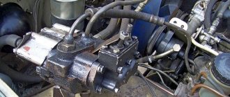
How to make a reduction gearbox for an engine
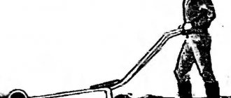
Home craftsmen try to equip their workshop with a variety of homemade devices that can make physical labor easier and improve the quality of work.
Such a useful device can be considered a reduction gearbox for a walk-behind tractor or mini tractor. This product is used to reduce the speed of the engine working shaft and increase its torque.
Before making a gearbox with your own hands, you should carefully study the instructions.
How to make a reduction gearbox with your own hands: algorithm of actions
Currently, many owners of home workshops equip them with modern tools and equipment, which, being highly efficient and easy to use, significantly facilitates work and increases its productivity. However, at the same time, quite technically simple devices that can be made with your own hands in a home workshop are still in demand. One of them is a reduction gearbox.
What is a reduction gearbox?
It is a special type of mechanism that serves as a transmission link between devices in which the active parts perform rotational motion.
It is often used to transmit and convert torque from the unit that produces it to the device that uses the mechanical energy supplied to it.
Unlike other types, a reduction gearbox provides a reduction in the number of revolutions and an increase in torque.
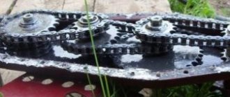
A reduction gearbox consists of a housing, gears, transmission chains, a worm mechanism, and shafts, with the help of which torque is transmitted and converted.
Toothed gears are located on the shafts in a rigid coupling, and worm gears are attached. They ensure the transfer of motion to each other, during which its transformation is carried out.
There are different types of reduction gearboxes:
In addition, they are:
Basic indicators
- efficiency;
- transmission power;
- number of rotations of the driven and drive shafts.
The reduction gear has a fairly simple design, so if you have the appropriate spare parts and materials, you can make it in a home workshop with your own hands.
Preliminary preparation
Before you begin creating this device, you must have general knowledge of mechanics, be able to use repair tools and equipment, and know the operating principle and structure of this unit.
In addition, you need to initially determine:
- the type of future gearbox and its version;
- the gear ratio that will need to be converted and determined at the output;
- indicators of dynamic loads that will affect the working parts of the device;
- weight and dimensions of the future device;
- installation angle;
- temperature limits that will occur in the device during its operation;
- switching cycle – full or variable;
- intensity of operation.
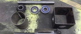
Parts and parts of the reduction gearbox
- Drive and driven shafts;
- Bearings suitable in diameter for axles and shafts;
- Sets of sprockets of a certain size with a certain number of teeth;
- Torque transmission chains;
- Sheet steel;
- Corner profile;
- Frame.
More details about the components
The assembly process is not as complicated as the selection or production of spare parts necessary for such a gearbox.
- Device body. In industry it is produced by casting. The necessary holes are made using high-precision equipment, since it is necessary to achieve the mutually correct arrangement of the shafts and the alignment of the stars. When producing it, it is necessary to make the top cover removable. This will facilitate and simplify the process of servicing it during operation;
- Shafts and axles of the gearbox. They support gears and are used if they need to be equipped with this device. Installation is carried out by pressing onto splines or keys. For their manufacture, it is better to use durable steel measuring from 10 to 45 mm, which is easy to machine;
- Bearings. They are used as supports for shafts and resist loads and provide the possibility of rotational movement. Its reliability, durability and performance depend on the correct selection of these gearbox elements. If you are installing spur gears, then it will be sufficient to install conventional single or double row ball bearings. If a helical bearing or worm gear will be installed, then a roller or angular thrust ball bearing will be the best option. It is better to buy new ones than to use them from disassembly;
- Gears. They provide a change in the rotation speed of the shafts and, naturally, a reduction in the gear ratio. For their production, special metal-cutting equipment is used, which home workshops are not equipped with. The dimensions and characteristics of other parts included in this unit, as well as the distance between the axles and shafts, depend on the size of the gears. When installing, it is important to correctly set the gap between them. I-20 oil is perfect for lubricating gears. It is filled to the level of the bottom of the gears. Other parts of the device are lubricated by spraying lubricant onto them. You can take it from disassembly or buy new ones;
- Oil seals. They prevent oil from leaking out of the device body. They are installed at the exit points of the shafts on bearings under the covers. Are bought;
- Safety coupling. It is designed to prevent destruction of the device when excessive loads occur. Buyable;
- Bearing caps. They can be different - deaf and through. Designed to facilitate maintenance and installation of bearings. You can grind them yourself or find them at a disassembly site.
Where is the device used?
A reduction gearbox has many advantages. Its design allows you to increase the productivity and profit of large industrial enterprises. It can also be considered an indispensable assistant in the household.
Experts highlight the following areas of application of the device:
- in industry;
- in car gearboxes;
- in various electrical equipment.
At large enterprises this product is used quite widely.
In various machines for metal processing, the gearbox is used as a rotary transmission unit, which increases the number of revolutions. In gearboxes for automobile transport, a device is installed that reduces the engine speed. The softness and smooth running of the machine directly depends on the quality of adjustment of the gears of the gearbox.
This product is widely used in electrical equipment and household appliances, such as rotary hammers, drills or mixers. Gearboxes can be considered the main parts of ventilation, planetary, pumping and cleaning systems, because they are able to maintain optimal operating pressure.
Do-it-yourself reduction gear: description, diagrams, drawing and reviews
A reduction gearbox is a device that is designed to convert torque. There are worm, planetary and combined modifications. The engine with gearbox is capable of operating at high speeds. The standard model consists of a shaft, pushers and gear. If necessary, you can make a step-down device yourself.
Worm modification diagram
The worm gear design includes a wide disk with a gear next to it. The first pusher is located at the base of the gearbox. In this case, the coupling is attached to the front of the housing. To make the device yourself, first of all, a stand for the shaft is cut out. Next you need to secure the disks. Lastly, the retainer is soldered.
Assembling the planetary device
This reduction gearbox for an electric motor is distinguished by the fact that it uses a two-chamber gearbox. Pushers for modifications are installed in different sizes. To make a device with your own hands, a wide block is prepared. Next, it is important to install the pushers. The coupling is directly fixed to the clamping spring.
Experts recommend grinding the stand in advance and welding supports on it. The gear is fixed at the rear of the gearbox. The pressure plate is installed only with a stop. The clamps can be mounted with a roller mechanism. It should also be noted that there are many homemade modifications with additional stops that stabilize the shaft.
Helical gearboxes
Recently, a cylindrical homemade reduction gearbox has been actively used. You can make the device with your own hands with a short and long shaft. In this case, the stops are installed in the rear part of the housing. Some devices are assembled with one gear. Before installing the part, a block for the disks is prepared. The gearbox shaft is fixed on the stand.
The holder is allowed to be made with an emphasis. Ball bearings are fixed at the base of the shaft. Pressure plates for models can be of different sizes. If we consider compact devices, then the spring should be installed with a small diameter. It should also be noted that the gears are placed behind the shaft. The pushers should not come into contact with the disk. A cap is screwed onto the front of the housing.
Conical model drawings
This reduction gearbox can be made with longitudinal pushers. Drives are most often mounted on a short stand. A lever is installed to switch the clutch.
Many modifications are assembled with an adapter holder. The shaft is fixed behind the rack. A clutch is used to adjust the tension. At the end of the work, all that remains is to secure the lid.
The engine with reduction gearbox is capable of operating at a frequency of 50 Hz.
Reviews of combined devices
Combined gearboxes that reduce speed are highly valued among professionals. If you believe the reviews, the models are well suited for asynchronous motors. It is more expedient to use pushers made of steel plates.
Stops are used to install the discs. The coupling for modifications is fixed behind the shaft. If you believe the reviews of experts, the retainer can be cut from a regular plate.
It should also be noted that it is more advisable to install the cover with a screw clamp.
Modifications with one lock
Making a reduction gearbox with your own hands is very simple. In this case, the pushers must be installed under the stops. The box for modification can be selected as a single-chamber type. Gears can be used with a clamp.
Pressure disks are installed with a roller mechanism. The pressure disk is fixed in front of the pusher. To install the spring, use a hammer. The clutch is mounted under the disc.
Ball bearings can be used in different sizes.
Devices with two clamps
Modifications to two clamps fold with a dual camera. A total of two disks are required for assembly. The coupling itself is matched with a support spring.
Many experts say that it is more advisable to use U-shaped pushers. A lever is used to change gears. If you believe the reviews of experts, then the gears take a very long time to fill.
In this case, it is important to fix the shaft at the base of the chamber. At the end of the work, all that remains is to make a holder for the rollers.
Models with front pushrods
Reduction gearboxes for walk-behind tractors with front-mounted pushers are capable of maintaining high speeds of an asynchronous engine. The holders of the modifications are installed with roller mechanisms. Many models fold with longitudinal stops.
Before starting assembly, a chamber for ball bearings is prepared. They are fixed on the bottom of the block. The driven disk is machined to a small diameter. It should also be noted that it is important to securely fix the stops. A cover must be attached to the rear of the gearbox.
Rear pusher gearboxes
The reduction gearbox with rear pushers is in great demand. First of all, it should be noted that the models are compact. At the same time, the devices cope well with heavy overloads. The disadvantage of the models is the rapid wear of the discs. This happens due to friction of the stops. If necessary, modification can be done by yourself.
For this purpose, experts recommend preparing a narrow block and installing disks with a roller mechanism. It is more expedient to place the gear after the pushers. It should also be noted that there are modifications with brake stops. In this case, the pushers are fixed on the rack. To change gears you will have to install a lever.
After this, the drive disk is fixed. The cover for the gearbox can be selected with a screw connection. Pressure plates are usually fixed near the front pillar. The model holder fits with or without a stop. If you believe the reviews of experts, then gearboxes with two pushers are considered the most popular.
Reviews of one-stage modifications
Most experts speak positively about single-stage gearboxes. However, it is important to understand that high-quality models are assembled with adapter pushers. They use sharpened heads and do not rub against the discs. It is more expedient to install the gearbox shaft behind the partition. The gear is most often fixed in front of the rack.
It should also be noted that there are compact modifications with a small shaft. They have small pressure disks; the device is not able to maintain high engine speeds. The holders are installed in a cylindrical shape.
Pressure plates are used with and without adapters. Rollers are used to reduce friction, and bearings are installed at the base of the shaft. It is important to pay special attention to the block during assembly. In order for the case to withstand heavy loads, it must be carefully soldered.
At the end of the work, all that remains is to weld the lid.
Assembly of two-stage devices
The two-stage reduction gearbox is capable of working with high power asynchronous motors. Modern models are available with longitudinal pushers. If necessary, a two-stage modification can be made independently. For this purpose, a block is taken and working disks are placed.
It is important to carefully grind the shaft and solder a wide head. A small rod is used to secure the gear. The retainer is most often installed in the front part of the gearbox. The stop can be machined from an ordinary steel plate of small thickness. The modification shaft must not come into contact with the working discs.
It should also be noted that the devices fold with and without a coupling. If we consider the first option, then a clutch lever is installed in the block. In this case, the spring is selected with a small diameter. It is better to fix the pressure stop on the device box.
Worm modification diagram
The worm gear design includes a wide disk with a gear next to it. The first pusher is located at the base of the gearbox. In this case, the coupling is attached to the front of the housing. To make the device yourself, first of all, a stand for the shaft is cut out. Next you need to secure the disks. Lastly, the retainer is soldered.
Conical model drawings
This reduction gearbox can be made with longitudinal pushers. Drives are most often mounted on a short stand. A lever is installed to switch the clutch. Many modifications are assembled with an adapter holder. The shaft is fixed behind the rack. A clutch is used to adjust the tension. At the end of the work, all that remains is to secure the lid. The engine with reduction gearbox is capable of operating at a frequency of 50 Hz.
How much oil to pour into the walk-behind tractor gearbox
When operating the walk-behind tractor, it is necessary to maintain a constant oil level in the gearbox. If this simple rule is not followed, lubricant residues may boil and jam the parts. Only high-quality oil is poured. Even with constant maintenance of the level, breakdowns occur. During chain transmission, the chain breaks or is pulled out. If traces of oil appear on the outside, this is a sign of leaking seals. Worn parts require replacement with similar ones. It is better to purchase them from a reputable manufacturer.
The gearbox ensures uninterrupted operation of the walk-behind tractor, extends its service life and increases the efficiency of use of the unit. A good helper in this matter is to lubricate its parts. Transmission oil is poured in for lubrication. Its possible brand is ZIC 10W40, Super T-3. The oil level is determined in this way:
- you need to take a wire approximately 70 cm long instead of a probe and bend it into an arc;
- insert into the filling hole until it stops;
- pull the homemade dipstick back;
- the wire should be oiled to a length of about 30 cm.
This level is considered to be the norm. If there is little oil, you need to add it to the norm. In a purchased gearbox, the level must be indicated in the instructions. A Chinese walk-behind tractor can be sold without oil.
Models with front pushrods
Reduction gearboxes for walk-behind tractors with front-mounted pushers are capable of maintaining high speeds of an asynchronous engine. The holders of the modifications are installed with roller mechanisms. Many models fold with longitudinal stops. Before starting assembly, a chamber for ball bearings is prepared. They are fixed on the bottom of the block. The driven disk is machined to a small diameter. It should also be noted that it is important to securely fix the stops. A cover must be attached to the rear of the gearbox.
Modifications with one lock
Making a reduction gearbox with your own hands is very simple. In this case, the pushers must be installed under the stops. The box for modification can be selected as a single-chamber type. Gears can be used with a clamp. Pressure disks are installed with a roller mechanism. The pressure disk is fixed in front of the pusher. To install the spring, use a hammer. The clutch is mounted under the disc. Ball bearings can be used in different sizes.
Read also: How to replace a fuse in a microwave oven