Anyone who has at least once tried to unsolder a microcircuit with a soldering iron has probably experienced certain difficulties. This is explained by the fact that in order to desolder a large number of legs, it is necessary to either warm them all up at the same time, or free them from solder one by one.
Only in this case is it possible to keep the contacts on the board in good condition, which allows you to subsequently solder in a new chip. If you are not completely sure that an expensive part is faulty, it is natural to want to keep it in working order without overheating during dismantling.
Features of dismantling
There are many known technical techniques that allow you to solder a microcircuit with a soldering iron, each of which has its own advantages and disadvantages.
You can remove electronic parts from boards without damaging the contacts in the following ways:
- by heating the soldering areas with just a soldering iron (with the addition of flux);
- through a special suction that removes molten solder from the contact pads;
- using a metal braid from a coaxial cable applied to the soldered leg;
- using heat-conducting metal plates (blades) or copper attachments that have slots for the contact patches of microcircuits.
The first three methods are suitable if you have a soldering iron whose power exceeds 25 watts.
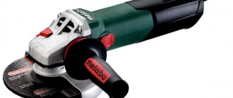
The option of using special attachments involves replacing the working tip and is only suitable in combination with “powerful” soldering stations (more than 40 watts), capable of heating it together with the contacts soldered into the board.
In addition, this method of desoldering a part is only suitable for microcircuits with a suitable arrangement of legs for the configuration of the nozzle. The approach that has become more widespread is when a regular razor blade is used as a heater.
Tools we will need
Many of the tools may already be available to DIY radio enthusiasts. Otherwise, you will have to purchase them or make them yourself from scrap materials.
Therefore, before unsoldering the radio component, get the following devices:
- A soldering iron of the required power and design for heating the contacts of radio components . You can take a ready-made one, or you can make it yourself; the manufacturing process is described in detail in the following article:
- Tweezers or clamp - used for manipulating radio components. Allows you to hold elements with tweezers, fix their position and provide additional heat removal when you try to desolder them.
- Tubular-shaped needles are sold ready-made, but if you don’t have any on hand, they can be replaced with a regular medical syringe needle, the main thing is that the inner diameter fits onto the stem of the radio component. In addition to needles, you can use tubes or sleeves; with their help, heated radio components are separated from the solder.
Rice. 1. Set of soldering needles
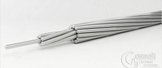
- Dismantling braid also acts as an auxiliary tool if you need to desolder those elements that have a large number of legs on the printed circuit board. You can either purchase a ready-made one or make it yourself.
Rice. 2: dismantling braid
- A desoldering pump is a device for removing solder from a mounting location, allowing you to quickly desolder a large number of radio components. Structurally, it includes a vacuum flask, a return spring and a piston driven by it. In addition to purchasing a factory model, you can make a desoldering pump yourself.
Rice.
3. Desoldering pump Inexperienced electricians may argue that so many tools for desoldering radio components will be too many. After all, soldering is performed using a regular soldering iron, but all of the above devices will help you solder the necessary elements quickly and accurately. This is especially true with large volumes of contact pins in the board. Now let's look at the practical application of each of the tools described above.
One soldering iron
You can unsolder parts from the board with a regular soldering iron if you grab the solder with a tip dipped in flux.
The essence of this well-known method is that after removing the next portion of molten tin, it is shaken off or wiped on a damp cloth. With each approach, the tip tip is re-wetted with a brush with fresh flux, after which the next portion of the melt is captured. Before wetting, it is recommended to warm the tip well in regular soldering rosin.
To smoothly remove parts with a large number of contacts (excluding planar microcircuits), this operation must be repeated several times. When performing this, you need to ensure that the contact patches do not overheat and subsequently come off along with the legs.
After the bulk of the solder has been removed from the connecting pads, it will be possible, with a little effort, to pry the microcircuit from the side of the board and separate it, desoldering it completely.
Reballing procedure
To carry out reballing, the chip is placed in a stencil and secured with specialized electrical tape. Apply solder paste on the back side with a finger or spatula, then set the hair dryer to a temperature of about 300 degrees and begin to warm it up. After the characteristic shine from the molten solder paste appears, allow the solder to cool completely.
To free the stencil from the chip, remove the electrical tape and heat the stencil to approximately 150 degrees; at the end of the procedure, the part should be free. It happens that it is impossible to immediately remove a part from a Chinese stencil, so it may be necessary to carefully hook it.
During reverse soldering of the microcircuits, the risks are assessed and the chip is laid out the required number of times to ensure an exact match of the heels and balls. Then they set the temperature on a soldering hair dryer to 330 to 350 degrees and heat until the melted solder allows the chip to fall into place on its own.
A soldering station is an indispensable tool for an electronics engineer. Usually the station comes with both a soldering iron and a hair dryer. If you learn how to use them, then almost any soldering will seem exciting and not very difficult.
A special feature of the stations is temperature control. You need to immediately remember an important rule - avoid temperatures above 400 °C or more. Many beginner (and even experienced) radio amateurs neglect this. These are critical values for microcircuits and boards.
Solder melts at approximately 180 to 230°C (lead-containing solders) or 180 to 250°C (lead-free). This is far from 400 °C. Why then set the temperature high?
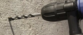
Using a razor blade
The main problem with soldering microcircuits is that they have several legs, which is why when one of them heats up, the others have time to cool down. This inconvenience can be overcome by using a heat-conducting device that contacts several legs at once.
In this case, the thermal power of the tip is distributed evenly between them and ensures that the solder melts in several contact areas at once. A simple razor blade can be used as such a device; to heat it up, you will need a soldering iron of suitable power or a hot air gun.
When heating the steel blade, it is recommended to slightly rock the chip on the soldered side, after which you can forcefully pull it out of the board. In the same way, the second row of legs is freed from solder.
Additional training
For additional training, you can try soldering various unnecessary boards from computers and smartphones. There are many SMD and DIP components on motherboards. Only long and hard hours of practice will help you develop your soldering skills.
Net
As an exercise, you can try soldering a grid of wires. The quality of soldering is assessed by the load on this soldered wire mesh. If the solder joints do not break under load, then the soldering is excellent.
Constructors
Radio designers are also a great help.
They teach you to understand electrical circuits and the intricacies of soldering. You should start with simple constructors, such as flashing lights or door locks. As your skill increases, you can increase the level of difficulty, reaching complex LED cubes.
Soldering with acid
Acid is used only as a last resort, when a heavily oxidized surface cannot be tinning. All parts, wires and connectors can be soldered perfectly without acid. Read more about soldering acid
Using a special braid
Removing microcircuits with a soldering iron is based on the ability of its tip to attract solder. This is explained by the fact that a high-quality tinned and flux-treated tip is characterized by increased wettability (that is, it grips solder well when soldering).
This effect can be enhanced by using the braid removed from the coaxial cable. Its role can be played by the screen from the antenna wire, removed from it and generously moistened with flux.
If you press the unbraided “braid” of the screen to the contact patch, and then “walk” over this place with a soldering iron, you can observe an interesting effect. Due to the porosity and high hygroscopicity of the braided structure, it absorbs solder well, gradually freeing the chip body with legs.
Chip types
The wide variety of microcircuit packages has led to the fact that soldering techniques began to differ. Previously, the most widespread were microcircuits with pin pins for mounting into holes on a printed circuit board. Subsequently, with an increase in the degree of integration and the widespread use of automated soldering lines, surface mount elements with flat or ball leads began to be used.
ICs (integrated circuits) with solder pins are typically DIP and SIP packages with two and one row of pins, respectively.
Surface mounting ( SMD ) allows installation of ICs with pins of the following types:
- Flat leads brought outside the housing - SOIC, SOP, QFP (square housing);
- Flat legs, bent inward, under the body - SOJ, PLCC, QFJ;
- Ball terminals - BGA.
Each variety has several subspecies. The total number of housing types is in the dozens.
DIP housing
Dismantling by suction
This method of soldering microcircuits and other small parts is based on the principle of liquid suction by creating a vacuum in the contact area.
Vacuum, in turn, can be created using the following tools:
- a special device that operates on the principle of a bicycle pump (it is called a destin pump);
- suction in the form of an enema, which can be combined with a soldering iron and used simultaneously with heating the contact pad.
Suction structures can have a variety of designs (in the form of a piston with a rod, for example), but their essence does not change. They have been and remain the most effective means of removing liquid solder.
Assembly order
Direct assembly of the soldering device is carried out in the following sequence.
First, a nichrome spiral with a cross-section of about 0.4-0.5 millimeters is wound onto a tubular frame with a diameter of 5-6 millimeters. The total length of the wire segment is selected based on the required electrical resistance (at least 70-90 Ohms).
As a tubular base, you can take the corresponding part from a store-bought product (soldering iron) type EPSN-100.
When winding an element, individual turns of the spiral should be laid with equal spacing, so that they do not touch each other. After this, the finished spiral heater is tightly wrapped with a piece of fiberglass of the required size, and on top is wrapped with an asbestos gasket.
The latter is fixed to the fiberglass using heat-resistant glue, after which a heat-insulating tube pre-measured in size is put on it (porcelain, ceramics or quartz glass can be used for this).
Upon completion of the assembly of this unit, the ends of the wound and protected spiral are brought out.
Then the finished heating element is inserted into the outlet channel of the body of the old hair dryer, which is pre-insulated with any heat-resistant material at hand (mica, asbestos or quartz).
Use of medical needles
In the absence of a special suction device, a novice master can use a medical needle to remove the microcircuit. It must be thin enough to fit into the hole being vacated. At the same time, the needle must have a thickness that allows it to be put on the soldered leg.
Before starting operations, you need to file the tip so that the oblique cut turns out straight, and then flare it a little.
Soldering the part with the resulting device is not difficult at all. To do this, you first need to put the needle all the way onto the pin of the microcircuit, and then use a soldering iron to heat it together with the contact.
While the solder is in the liquid phase, slightly turning the needle, you should push it into the mounting hole (it is advisable to continue rotating until the melt sets).
Upon completion of this procedure, the end of the needle along with the leg will be isolated from the board. Do the same with the remaining legs, after which the microcircuit is unsoldered and removed without any difficulty.
How to solder with a hairdryer correctly
It is necessary to cover all small components that are vulnerable to overheating with protection.
In this case, aluminum tape is used. It protects components well from temperature and holds the board components tightly. However, it adds heat capacity to the soldering area. Thermal tape also protects well, but sticks to the board less well.
The board is placed on a material that has the least heat capacity and slowly releases temperature to the environment. You can use, for example, a wooden plank. And at the same time, the soldering area should not be inclined.
It is best to apply flux to the contacts. It distributes heat well compared to heated air, but you should not add too much of it. It may boil, hiss, or interfere with soldering.
The first step is to warm up the soldering area. The hair dryer is set to about 100 °C and maximum air flow.
It is necessary to warm up both the part itself and the surrounding soldering area with contacts in a circular motion.
Next, after about a minute, you should gradually increase the heating.
The difference with the contacts will be small. Thus, within a few minutes, increase to 300 °C.
Steps of about 20 - 30 °C for every tens of seconds.
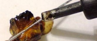
Use of Rose alloy
You can also unsolder and remove the microcircuit from the board using special compounds called “Rose” or “Wood” alloys. Their distinctive feature is their low melting point (no more than 100 degrees).
Before soldering the microcircuits using this method, several granules of the selected composition are poured directly onto their contacts. After this, using a well-heated soldering iron, a bath of solder is made, spreading evenly over all the legs.
Thanks to the action of the granules, the overall melting temperature in the melt bath will also decrease, which will lead to uniform spreading of liquid solder over the entire plane of the contact pads. In such a heated state, you need to try to pull the microcircuit out of the socket by grabbing it with tweezers.
Analyzing the methods of dismantling microcircuits, it can be noted that all of them can be implemented at home (watch the video). To do this, you only need appropriate preparation, which consists of making the necessary tools with your own hands and purchasing the necessary compounds.
Desoldering pump for desoldering radio components
The destin pump is used like this: cock the spring, bring the tip to the contact heated by the soldering iron and press the spring release button, due to the created vacuum, the molten solder is drawn into the destin pump. I use the one in the photo, if the desoldering pump stops drawing in solder, you need to disassemble and clean the rubber ring on the piston. These methods (braiding and desoldering) have advantages over heating the soldering area with a soldering hair dryer in that, for example, when desoldering plastic connectors for further use, there is no risk that they will melt. Also, a syringe needle is suitable for eliminating short circuits between “stuck together” adjacent legs of microcircuits. In this case, we warm up the soldering area with a soldering iron and pass the needle between the legs of the microcircuit in order to separate them so that there is no contact between them. Review prepared by AKV
.
Soldering microcircuits from the board is a non-trivial task, regardless of the type of controller. You unsolder one leg, but while you are working on the other, it freezes. You can bend the legs after unsoldering, but the problem of contacts breaking off again arises. The question arises, how to desolder a microcircuit from a board with a soldering iron? The answer is quite simple: use knowledge of physics and available objects. There are a number of options for carefully removing microchips from the board. But first, a little theory.
What is soldering
From a technology point of view, soldering is the operation of permanently joining parts made of various materials, performed using a low-melting metal or alloy. Solder in molten form is introduced between two products remaining in the solid phase state, flows into their smallest pores and, solidifying, firmly connects them.
People started soldering with a soldering iron, heating it over an open fire. Such work required great skill and even a certain mastery; it took the student years to learn how to solder. At the beginning of the 20th century, electric soldering irons appeared that maintained a constant temperature of the tip, and since then anyone can master the basics of soldering in a few hours. Soldering with a soldering iron has lost the secrets of the craft and has become a common skill of the home craftsman. However, the electric soldering iron does not solder itself, and certain soldering rules must be followed.