A goniometer geodetic instrument used to measure angles in the horizontal and vertical planes, called horizontal and vertical, respectively. Together with measuring the distances between points, further calculations and adjustment, the final result is obtained in the form of spatial coordinates of the points taken.
Theodolites have their own history of development. Initially, its design was a mechanical device with a metal goniometric circle (limbo), with an additional reading device (vernier), and a telescope. With the advent of glass circular dials, an optical system for transmitting and reading angular readings (microscope), the era of optical theodolites arose. With the emergence of new electronic computing technologies, new types of theodolites, called electronic, began to be introduced into geodetic instrumentation. They use a binary system for encoding readings on the dial with the transfer of digital information of angular measurements to the display screen.
Currently, the use of optical theodolites, due to their weak competitive ability with the latest electronic total stations, can be considered applied. Perhaps in the future they themselves will become history. But now they can be used:
- in northern regions with extremely low temperature conditions in winter, in which not all electronic equipment works;
- in underground mine construction with dangerous and harmful external factors;
- during marking work in the construction of low-rise buildings and underground utilities;
- to perform individual geodetic processes using the geometric capabilities of the device (laying out formwork, reinforced concrete and metal structures of all kinds, as-built surveys);
- Other applications are also possible, related to solving various problems with engineering ingenuity.
Classifications and types of theodolites
In accordance with state standards, all theodolites, according to the design accuracy of measuring horizontal angles, are divided into groups:
- high-precision (T1, TB1), with a root-mean-square error (RMS) of measuring a single angle of no more than one second;
- accurate (T2, T5) with SKP no more than five seconds;
- technical accuracy (T15, T30), which includes all other goniometer tools.
Due to the design features of the instruments, in the nomenclature of theodolites, after the SKP values, alphabetic symbols are indicated, indicating the corresponding type of instrument:
- 2T5K, with compensator;
- 4T30P, with direct image;
- 3T2KA with autocollimation eyepiece;
- 2T30M, mine surveyor;
- T30, without letter designations, means a traditional tool with a cylindrical level with a vertical circle.
Depending on the design of the elements of the horizontal circles, the static or rotating position and the relationship between the limb and the alidade, two more types of tools can be distinguished:
- repeating, allowing the limb to rotate or not rotate together with the alidade around the axis, when the alidade is secured and the limb is detached;
- non-repeating devices with only the fixing function of the dials.
Each optical theodolite can also be classified into a type depending on its intended use:
- geodesic;
- mine surveyor;
- astronomical;
- total station, which were theodolites marked TT and models T5, T30.
Correct operation
Compliance with the rules for operating a theodolite will prevent serious errors when taking measurements. These rules include the sequence of actions at various stages of operation of the device:
- during storage;
- in preparation for work;
- during measurements;
- sequence of evaluation of the results obtained;
- procedure for assembling the theodolite after work.
Particular attention should be paid to all these rules under special environmental conditions: temperature, humidity, wind strength, lighting. Almost all theodolites have a temperature range permitted for operation from -25 °C to +50 °C of any humidity. However, it should be remembered that too low or high temperatures will affect the accuracy of the readings taken.
Theodolite device
All groups of theodolites have practically the same basic design. It includes the following main parts:
- a base with a stand on which the rotating part of the tool is fixed;
- the actual rotating part, consisting of a lower horizontal circle with a cylindrical level, two vertical columns (one with a vertical circle and a tilt compensator), a telescope and a reading microscope.
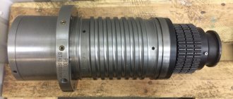
A more detailed structure is depicted in detail in Fig. 1. Appearance of the T30 optical theodolite. Each individual node has its own purpose and is interconnected by geometric and structural connections.
A wide metal platform (1) is used to mount the instrument on a tripod using a mounting screw.
The horizontal circle (2) in the lower part of the device body consists of a reading mechanism (alidade) with a fastening screw (3), a micrometer guidance screw (4), and a cylindrical ampoule of a horizontal level (5) for rotation through 360º.
The vertical circle (19), which is a single unit with the vertical stand (12), contains a reading device with a backlight mirror (16) and a groove for fixing the compass (18). Its purpose is to measure vertical angles (inclination).
The second vertical stand is equipped with a fixing screw (8), a ratchet (7) for focusing the image, and a vertical circle micrometer screw (6) for precise alignment of the telescope.
The telescope, structurally fixed between two posts, includes a viewfinder (9), an eyepiece in the form of a lens for viewing the image in the field of view of the tube (10), an eyepiece of the reference microscope (11) and a lens (17). It is designed for aiming at sighting targets.
The design of the tribrach (21), containing lifting screws (15), contains a dial in the form of a round ring with marked divisions on its scale (13), its fastening (14) and micrometer (20) screws.
Fig. 1. Appearance of the T30 optical theodolite
Optical theodolites, whose main purpose is to measure angles, represent a design scheme consisting of three systems:
- measuring;
- guidance;
- orientation.
The orientation system includes geometric mutual connections of vertical and horizontal positions between the axes of rotation of the tool, levels and plumb lines.
The guidance system includes rotating mechanisms, geometry and telescope optics.
The measurement system represents vertical and horizontal circles with scales on both dials, alidade reading devices and an optical microscope.
How to use a total station
When using total stations, two workers are usually required: one operates the station itself and takes measurements, and the other moves to the position of the point at which the station is aimed.
This worker is usually equipped with a rod-rod containing a reflecting prism from which the beam is reflected back to the total station. Such devices are called double total stations.
However, the most modern devices are already designed to be operated by one worker, so-called robotic total stations, operated by one person.
- In robotic mode, they can measure distances without reflection or independently aim at the point being measured.
- Currently, total stations are increasingly used together with or even replaced by precise GPS surveying devices.
But there are types of activities in which it is impossible to do without a theodolite. For example, when measuring and delineating property boundaries in forested or densely built-up areas, accurately delineating the perimeter of brickwork and partitions on buildings, or measuring 3D coordinates in interiors.
Theodolite measurement system
It is a mechanism for reading angular readings from the scale of a fixed limb ring relative to the stroke of a movable alidade and transmitting them through the optical system to the microscope eyepiece. Reading is carried out in some models of instruments along a horizontal and vertical circle on one side of the dial (one-sided system), and in other instruments along two sides (two-sided). A line microscope with a single-sided reading system is shown in Fig. 2. Vertical and horizontal angle measurements.
Fig.2. Vertical and horizontal angle measurements.
In different theodolites, depending on their accuracy and design features, the reading devices can be of another type: scale microscopes, optical micrometers.
Electronic total stations
It was only a step from optical or digital theodolites to the creation of a device that is now commonly called a total station.
Unlike a theodolite, a total station uses a beam of light to measure distances with an accuracy of millimeters, and the range of such a rangefinder is in kilometers. Thus, an electronic theodolite supplemented with a laser range finder is called a total station.
The total station allows you to work with horizontal angles, elevation angles, distances and converts to rectangular coordinates.
- The distance is determined with millimeter accuracy thanks to the built-in light rangefinder.
- The measured values are stored in memory and can be transferred to a computer for further processing.
- You can also import coordinate data into the device and plot and stabilize it in the field.
Theodolite guidance system
Consists of a telescope and associated micrometer screws for precise targeting of the observation target. The telescope itself consists of a metal body, an optical system consisting of a lens (1) with an eyepiece (2), a reticle (5), a focusing lens (3) with a ratchet (4). The optical diagram of the main part of the guidance device is shown in Fig. 3. Spotting scope.
Fig.3. Spotting scope.
Sighting at distant points is carried out through the eyepiece lens and focusing the image using a screw or ratchet ring that moves the internal focusing lens. When a clear image appears in the lens, precise aiming at the target is performed using a grid of threads, the visibility of which is adjusted by the diopter ring. A line passing invisibly through the centers of the eyepiece and objective is considered the line of sight. The compliance of its position with the design and geometric conditions relative to the axes of other components of the optical device is verified by performing operational tests of the instrument.
Fig.4. The structure of the reticle (a) and the image in the field of view of the eyepiece in the T30 (b), T30M (c) devices.
Historical excursion
Theodolites have been used in land management and geodesy since the 19th century to measure spatial coordinates. Unlike a simpler optical level, they are equipped with two mutually perpendicular axes of rotation and perpendicular lines of sight.
From this point of view, the design of modern digital theodolites has not changed in any way. Similarly, the condition is that the measured point must be visible through a theodolite telescope.
Since the theodolite detects 3 spatial coordinates, it is necessary that each theodolite is also equipped with a range finder. A theodolite equipped in this way is called a total station and allows one to simultaneously determine the horizontal direction, vertical angle and distance.
The measured coordinates are converted to rectangular coordinates using manual trigonometric functions manually (in the last century) or using software in modern instruments.
Testing and calibration of theodolite
Having received the device into operation, it is necessary to carry out tests to ensure compliance with its performance characteristics. With each of them in the packing box there must be an instruction manual or a passport with technical parameters, equipment, design and features of this particular model, technical and routine maintenance work, checks, methods for carrying them out, adjustments and corrections, allowing you to bring the device into working condition . Each specific modification of the instrument has its own design features. And the resulting manual will help you correctly understand the operational features, reading devices and other characteristic parts of the theodolite.
Regardless of whether the device’s passport contains a mark on its metrological verification, it is necessary to independently carry out standard verifications. The entire set of tests, as a rule, is recorded in a special verification log with their results. Standard verifications for compliance with the geometric conditions of the axial elements of the theodolite include verifications:
- interaction of parts;
- levels, compensator;
- stability of the tripod and stand;
- tilting the horizontal thread of the thread grid;
- verticality of the optical plummet axis;
- determining the inclination of the horizontal axis of the device relative to the vertical;
- determining the collimation error and zero location;
- determination of the thread rangefinder coefficient;
- determination of the reading device ren.
Periodically, in addition to the usually annual metrological inspection, routine maintenance work is carried out throughout the year.