Screw-cutting lathe 16K20 (16K20P, 16K20G, 16K25). Electrical circuit diagram.
Device
Description of electrical circuit
The main drive electric motor M1 and the hydraulic station M4 are started by pressing button S4, which closes the circuit of the contactor coil K1, switching it to self-power. The main drive motor M1 is stopped by pressing button S3.
The electric motor for rapid movement of the carriage and support M2 is controlled by pressing a jog button built into the apron handle and acting on the limit switch S8.
The electric cooling pump M3 is started and stopped by switch S7. The operation of the electric pump is interlocked with the electric motor of the main drive M1, and it can only be turned on after closing the contacts of the starter K1.
To limit the idling speed of the main drive motor, the circuit contains a time relay K3. In the middle (neutral) positions of the main drive friction clutch engagement handles, the normally closed contact of the limit switch S6 is closed and the time relay K3 is turned on, which, after a set time delay, will turn off the main drive electric motor with its contact.
It is strictly prohibited to adjust the time delay in the operating state of the relay.
The electric motors of the main drive, the rapid movement drive of the carriage and support, the electric cooling pump and the transformer are protected from short circuit currents by automatic switches and fuses. Protection of electric motors (except for electric motor M2) from long-term overloads is carried out by thermal relays.
Locking devices
The electrical circuit includes a lock that turns off the input circuit breaker when the control cabinet door is opened. When the input circuit breaker is turned on, opening the cabinet door triggers the travel switch S1, which energizes the remote separator coil F1 and the circuit breaker disconnects the electrical equipment of the machine from the network. When the housing of the replacement gears is opened, microswitch S5 is activated, turning off the main drive motor. Limit switch S1 is mounted in the control cabinet, microswitch S5 is mounted on the feed box housing. For inspection and adjustment of electrical equipment under voltage (with the cabinet door open), the circuit provides a release switch S2 installed in the control cabinet. Switch S2 should be set to position 1, after which you can turn on the input circuit breaker and begin adjustment work. Upon completion of commissioning or repair work, set switch S2 to its original position 2, otherwise closing the cabinet door causes spontaneous shutdown of the input circuit breaker. On machines equipped with a hydraulic support, the main drive motor is switched off when the X5 plug connector connecting the hydraulic motor is disconnected. If such a machine is used without a hydraulic support, instead of inserting a plug connector, it is necessary to install a special plug supplied with the machine.
Electrical circuit diagram of a 16K20 lathe
16U04P Electrical diagram of a screw-cutting lathe
Electrical diagram of lathe 16u04p
Description of the circuit diagram (Fig. 19)
By turning the AB circuit breaker, voltage is supplied to the operating and control circuits.
When you press the 2KU button, the 1M electric motor rotates to the right using the KP starter.
When you press the 1KU button, contact 3-5 breaks the power supply circuit of the KP starter, and contact 3-29 turns on the circuit of the KT starter, which performs induction-dynamic braking of the engine. Contact KT (O-B11) short-circuits the first stator winding; contact (C1-C12) supplies pulsating current to the second winding through the power diode VK; contact (A1-A11) supplies alternating current to the third winding.
When you press the 3KU button, the 1M motor rotates to the left using the CL starter.
At points 23-25 n.a. contacts of the KP or CL starters prepare the KO starter for switching on.
By turning the HV switch, the KO starter is turned on. The KO starter with its power contacts turns on an electric motor 2M or 1M, or both electric motors simultaneously.
Protection
The electrical circuit of the machines provides protection for:
- from short circuit currents, carried out by fuses and a circuit breaker;
- overload protection provided by thermal relays;
- zero protection using magnetic starter coils.
Technical characteristics, description and passport 16K20
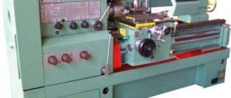
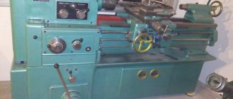
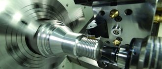
16K20 Screw-cutting lathe is a universal equipment for precise processing of metal products in full compliance with international quality standards. The objective advantages of machines of this type include convenient operation, wide functionality and excellent performance indicators, which guarantee high results and maximum efficiency when used correctly in repair, production and other metalworking enterprises. As a rule, screw-cutting lathes are used to perform technological operations of varying complexity with the external and internal surfaces of parts, including rotating bodies that have a varied axis profile. In addition, the 16K20 lathe is very often used for quick and convenient cutting of left-hand and right-hand threads (metric, inch, modular and pitch), fully meeting the needs of enterprises in all sectors of modern industry. The screw-cutting lathe 16K20 has an expanded package that includes all the necessary equipment to ensure successful operation:
- gearbox
- electrical cabinet
- feed box
- headstock
- chuck guard
- bed
- carriage and support
- apron
- caliper guard
- tailstock
Scheme
The basis and source of energy for any lathe is electric current. The 16K20 operating scheme is as follows.
16K20 Power supply circuit
The power supply and operation circuit of this machine is not original; all current is distributed evenly to the working “organs” of the unit in order to give it maximum power and excellent performance characteristics. Reasonable and rational distribution of energy throughout the machine allows you to perform work most productively, with optimal energy consumption. This is an important factor for any enterprise!
Technical characteristics of the lathe 16K20
| Accuracy class according to GOST 8-82 | N |
| The largest diameter of the workpiece installed above the bed, mm | 400 |
| Height of the center axis above the flat guides of the frame, mm | 215 |
| The largest diameter of the workpiece processed above the support, mm | 220 |
| Maximum length of the part installed in the centers (RMC), mm | 710, 1000, 1400, 2000 |
| The greatest distance from the axis of the centers to the edge of the tool holder, mm | 225 |
| The largest diameter of the drill when drilling steel parts, mm | 25 |
| The largest mass of the part processed in the centers, kg | 460..1300 |
| Maximum mass of the part processed in the chuck, kg | 200 |
| Spindle | |
| Spindle hole diameter, mm | 52 |
| The largest diameter of the rod passing through the hole in the spindle, mm | 50 |
| Spindle rotation speed in forward direction, rpm | 12,5..1600 |
| Spindle rotation speed in reverse direction, rpm | 19..1900 |
| Number of forward spindle speeds | 22 |
| Number of spindle reverse speeds | 11 |
| Spindle end according to GOST 12593-72 | 6K |
| Tapered spindle bore according to GOST 2847-67 | Morse 6 |
| Spindle flange diameter, mm | 170 |
| Maximum torque on the spindle, Nm | 1000 |
| Caliper. Submissions | |
| Maximum length of longitudinal movement, mm | 645, 935, 1335, 1935 |
| Maximum length of transverse movement, mm | 300 |
| Speed of fast longitudinal movements, mm/min | 3800 |
| Speed of fast transverse movements, mm/min | 1900 |
| Maximum permissible speed of movement when working on stops, mm/min | 250 |
| Minimum permissible speed of movement of the carriage (support), mm/min | 10 |
| Price for dividing the longitudinal movement dial, mm | 1 |
| Transverse movement dial division price, mm | 0,05 |
| Longitudinal feed range, mm/rev | 0,05..2,8 |
| Transverse feed range, mm/rev | 0,025..1,4 |
| Number of longitudinal feeds | 42 |
| Number of cross feeds | 42 |
| Number of threads to be cut - metric | |
| Number of threads to be cut – modular | |
| Number of threads cut - inch | |
| Number of threads to be cut - pitch | |
| Limits of metric thread pitches, mm | 0,5..112 |
| Limits of pitches of inch threads, threads/inch | 56..0,5 |
| Limits of modular thread pitches, module | 0,5..112 |
| Limits of pitch thread pitches, diametric pitch | 56..0,5 |
| The greatest force allowed by the feed mechanism on the cutter is longitudinal, N | 5884 |
| The greatest force allowed by the feed mechanism on the cutter is transverse, N | 3530 |
| Cutting slide | |
| Maximum length of movement of the cutting slide, mm | 150 |
| Movement of the cutting slide by one division of the dial, mm | 0,05 |
| Scale of rotation angle of the cutting slide, deg | ±90° |
| Scale division of the tool slide rotation scale, deg | 1° |
| The largest cross-section of the cutter holder, mm | 25 x 25 |
| Height from the supporting surface of the cutter to the axis of the centers (cutter height), mm | 25 |
| Number of cutters in the cutting head | 4 |
| Tailstock | |
| Quill diameter, mm | |
| Tailstock quill hole cone according to GOST 2847-67 | Morse 5 |
| Maximum movement of the quill, mm | 150 |
| Movement of the quill by one division of the dial, mm | 0,1 |
| The amount of lateral displacement of the headstock body, mm | ±15 |
| Electrical equipment | |
| Main drive electric motor, kW | 11 |
| Electric motor for fast movement drive, kW | 0,12 |
| Coolant pump electric motor, kW | 0,125 |
| Dimensions and weight of the machine | |
| Machine dimensions (length width height) RMC=1000, mm | 2795 x 1190 x 1500 |
| Machine weight, kg | 3010 |
Modern analogues
It has already been mentioned that the plant stopped producing the 16 to 20 model, so the selection of machines with similar characteristics is relevant. Foreign manufacturers are famous for the D420x1000, Proma SPC-900PA, Jet GH-1640ZX DRO units.
Belarusian analogues produced at the Gomel plant offer 16VT20P-21. You can also note the TRENS models from the Slovak manufacturer SN 50 C and SN 500 SA.
They have a modern design and high-quality German components, with a relatively low cost for their characteristics.
Prices for goods from other manufacturers start from one and a half million to two, without calculating the delivery and installation of units.
Machine design
The basis of the device is a durable U-shaped frame with 2 hardened, ground guides on top. It is installed on pedestals in a cast metal support, which is used as a trough for emulsion and collecting chips. The main electric drive is located in the cabinet on the headstock side of the product.
Dimensions of screw-cutting lathe 16K20
Machine dimensions: length 2505, 2795, 3195 or 3795 mm; width 1190 mm; height 1500 mm. The weight of the machine depends on its length and can be 2.835; 3.005; 3.225 or 3.685 per 103 kg.
Spindle
The spindle shaft is steel with a through longitudinal hole through which a rod is passed, used as a workpiece, or a drift when knocking out the front center. To rotate the spindle in this machine, specialized precision rolling bearings are used. They are distinguished by high manufacturing precision and wear resistance, so they do not require periodic adjustments during maintenance during the operational period.
The shaft supports are lubricated by oil supplied to them under pump pressure. The front end of the spindle shaft is made in accordance with GOST 12593 - with a short centering cone 1:4.
Headstock
The headstock or headstock of the workpiece serves to fix one end of the workpiece and transmit torque to it. It houses the spindle, bulkhead box and other components. On the outside there are switching levers for the bulkhead box.
The output shaft of the headstock of the product is connected through gears to the feed reducer. The latter allows the slide to carry out the feed movement using the drive shaft during turning. Or by means of a lead screw for thread cutting. Which can be connected to the feed box without intermediate links.
Apron
This unit is necessary to move the caliper with the tool holder both along and across the axis of rotation of the part. It converts the rotary motion of the screw into linear displacement of the caliper. You can move the latter not only manually, but also by taking away part of the rotational torque from the spindle. The apron of this machine is equipped with a high-precision feed cut-off device on a stop, a design that has not been seen before.
Caliper
Designed to hold the tool holder with the cutter fixed in it near the workpiece. Possessing several degrees of freedom, it can move under the influence of the apron to form the desired surface character of the part with a cutter. To control the amount of movement, the unit is equipped with scale rulers with sighting devices that increase the accuracy and ease of reading readings.
Tailstock
She's a stubborn grandma. It is installed on guides that allow it to move along the machine. It has a tapered hole coaxial with the headstock output shaft. Which allows you to set a center to support the second end of the blank. Or a reamer, tap, drill and other similar ones for performing operations from the open end of the workpiece.
Headstock of lathe 16k20
The headstock contains the gearbox and spindle assembly. The spindle transmits torque to the workpiece through devices. For installation and centering of devices, a flange is used, a conical neck is used for installing cartridges, and a conical hole is used for installing centers. In lathes, this hole is made using a Morse taper. The front ends of the spindles are standardized (for lathes with flanged front ends of the spindles GOST 12593-81).
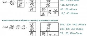
The guitar is used to adjust the feed chain using the selection of replaceable gears for cutting metric, inch, modular, pitch threads, as well as for adjusting the pitch (stroke) of the thread when cutting non-standard threads. In double-pair guitars, the distance L between the shaft I; shaft II is constant. A slope is freely mounted on shaft II, which is attached to the wall of the spindle head using a bolt.
Lathe apron 16k20
An apron is a mechanism for converting the rotation of a lead screw or lead shaft into translational movement of a caliper. The caliper receives translational movement from the lead screw through a split nut, and from the drive shaft through a series of gears through a rack and pinion gear.
This is interesting: TV-6 lathe - device, technical characteristics
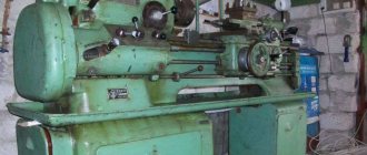
16K20 lathe
The screw-cutting lathe 16K20 is distinguished by its versatility; it can be used to turn rotating bodies, producing conical, cylindrical, shaped and screw surfaces.
Specifications
The drive power of the main movement is 10 kW. Maximum diameter of the workpiece: above the bed 400mm, above the slide of the caliper 220mm. Maximum processing length 1335mm. Rotation speed range 12.5…1600 rpm. The spindle is hollow, the maximum diameter of the threaded rod is 50mm. The workpieces are fixed in a chuck or on a faceplate. Steady rests are used to process long workpieces.
Drawing - General view
Features 16K20
- Possibility of processing fairly heavy parts - up to 300 kg in a chuck, up to 1300 - on a faceplate
- Large RMC models 750-2000mm
- Center height 215 mm on flat bed guides
- Maximum diameter of processed workpiece 400mm
- Powerful electric motor of the main movement - up to 11 kW
- Separate feed drive motor - 1 kW
- Rigid cast frame, guides are heat treated
- Height of centers
- Weight 2800…3600 kg, depending on version
Exploitation
To maintain good technical condition, it is recommended to regularly carry out technical inspections and preventive maintenance. The lubrication system is automatic. During operation, you should monitor the rotation of the spindle head oil indicator. If the oil indicator stops rotating, stop working immediately and clean the oil strainer.
CNC system
In order to be able to process parts in a semi-automatic cycle, the basic model of the machine was equipped with a numerical program control system, which later became known as the 16K20 F3 machine. The layout remains the same; many components, mechanisms and components have a similar design. The numerical control system controls the shaping movements of the working bodies along two coordinates. The system also provides regulation of the workpiece rotation speed, sets the necessary feed movements, and indexes the position of the cutting head.
Kinematic diagram
The kinematic diagram explains the connections and methods of interaction of the main mechanisms of the machine. The numbers of gear teeth (z) are indicated on the callouts; the number of worm starts is additionally indicated by an asterisk (*). At the top of the kinematic diagram there is a support with mechanical movement of the slide.
Main movement
The main movement in the machine is the rotation of the spindle, the movement of which is transmitted from the main electric motor through a V-belt drive. from pulley Ø140 to pulley Ø268. Next, the movement is transmitted to the gearbox receiving shaft. The double-sided friction clutch allows for both forward and reverse rotation of the spindle. Variations in the positions of the gear blocks allow you to obtain 12 different spindle speeds.
Figure - Kinematic diagram
Feed movement
The transmission of rotation from the output shaft (axis I) of the spindle head to the output shaft (axis II) of the feed box is carried out by installing combinations of replaceable gears in accordance with the feed table diagrams. 16K20 can be adjusted to cut various threads.
Replacement gears K and N for the 16K20 machine are mounted on splined shafts and secured with bolts through washers. Intermediate gears L and M are installed on the splined bushing of the axle, secured with a key.
Electrical circuit and equipment
Electrical equipment is protected using fuses and circuit breakers. The electrical diagram can be found in the instruction manual.
Major renovation
During a major overhaul, the machine is disassembled, electrical equipment is dismantled, the headstock and tailstock, apron, feed box, caliper carriage are dismantled, spare parts and consumables are replaced. Next, the components, mechanisms and parts are washed and inspected. Defective parts are isolated and, if repair is impossible, replaced with new ones. Next, both individual buildings and the entire structure are painted. The final stage of the overhaul is the testing operation. It should be remembered that before carrying out any type of work, it is necessary to familiarize yourself with the safety conditions and strictly observe them.
Price and equipment
The 16K20 model is currently out of production, and therefore, purchasing a copy that has not been in service becomes an almost impossible task. The price of such screw-cutting lathes starts from 100,000 rubles, and has an average value of around 200,000 rubles. Mainly, the cost is determined by the technical condition. There are often examples on the market that have undergone a major overhaul, including regrinding of guides, modernization or replacement of some components and electrical components. Currently, you can find modern analogues of turning machines from various manufacturers, the price of which starts from 1 million rubles.
The standard package includes the assembled 16K20 machine itself, including a 3-jaw chuck, a 4-position tool holder and a passport. Additional equipment includes movable and fixed rests, a four-jaw chuck and faceplate, as well as a quick-release tool holder.
Download the passport of the screw-cutting lathe 16K20
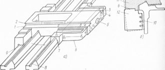
Design of the apron mechanism of the screw-cutting lathe 16K20
The apron mechanism is located in a housing screwed to the caliper carriage. From the running shaft, through a series of gears, the worm wheel and the wheel associated with it receive rotation. Both wheels sit freely on the shaft. From here the rotation is transmitted to the wheels, which sit freely on the shafts. These shafts are equipped with couplings with end teeth, which turn on the caliper feed in one of four directions.
The longitudinal movement of the caliper (to the left or to the right) is carried out when the clutches are engaged through the wheels, then through the wheel mounted on the bushing. The latter is connected by a movable key connection to a rack and pinion wheel, which transmits movement through the rack (not shown in the figure) to the caliper. The wheel can be released from engagement with the rack using a button. Transverse movement of the caliper (forward or backward) is carried out when the clutches are engaged. Then the movement of the gears is transmitted to the wheel, which sits freely on the bushing, and then to the caliper cross feed screw.
Shaft 1 carries a gear, which through the wheels imparts rotation to the disk and through it to the limb. Manual longitudinal movement of the caliper is carried out by a steering wheel through the wheels, bushing and rack and pinion.
Adjusting the apron mechanism of the machine 16K20
The force developed by the feed mechanism is regulated by turning nut 11. The amount of force is determined by a dynamometer, which must be installed between the rigid stop 47 (Fig. 28) and the carriage 19 (Fig. 27). Care should be taken to ensure that the amount of force does not exceed the permissible value according to the table. 1 (section 19).
The queen nut 62 mounted on the bracket 61 is adjusted at the factory.
If it is necessary to restore or replace a worn nut during repairs, you must use a special jig and tap, drawings of which can be sent upon request.
The backlash of the screw 20 of the drive of the transverse slide 11, which occurs when the nuts 22 and 23 are worn, is eliminated as follows.
The cover 12 is removed and the lock nut 15 is unscrewed using a drift (bit) made of soft metal. The clearance in the screw pair is selected by rotating the nut 14. The amount of the gap is determined by the dial 40 with a slight turn of the handle 33. The optimal value of the gap in the screw pair corresponds to the free play within one division of the limb. Then the locknuts 15 are tightened and the cover 12 is installed.
The rear tool holder 8, available as an option, is mounted on a cross slide, as shown in Fig. 27.
If, as the handle 4 wears out in the clamped position, it stops in a place that is inconvenient for the turner, then by grinding or replacing the spacer ring 1, you can set the handle 4 to the required position.
If the accuracy of fixing the tool holder 43 decreases, it is necessary to disassemble the cutting head and thoroughly clean the working surfaces of the mating parts. When crushing the tool holder, it is necessary to grind in the cones.
Setting the optimal gap between the carriage 19 and the strips 18, 64 and 66 is carried out by grinding the latter.
The clearance in the guides of the cross slide 11 and the cutting slide 9 is selected by tightening the corresponding wedges 52 and 42 using screws, the heads of which are located in the holes of the protectors 41 and 49.
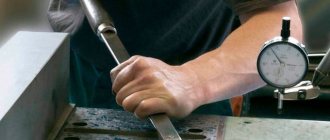
For the convenience of determining the movement values of the cutting and cross slides when processing parts, the support is equipped with scale rulers.
On the cutting slide 9 there is a ruler with a division value of 1 mm.
The counting is carried out using the sighting device mounted on the rotating part 10 of the caliper.
On the carriage 19 there is a ruler with a division value of 10 mm by the diameter of the product, which is used to control the amount of movement of the transverse slide 11 using a viewfinder attached to them.
The design of the ruler mounted on the carriage provides for the installation of a rigid stop for transverse movements, supplied upon special order.
A rigid micrometric stop 47 for limiting longitudinal movements is mounted on the front shelf of the frame with two screws 82.
The machine model 16K20P is equipped with a support with a mechanical drive of the cutting slide (Fig. 29, 30), which can also be supplied with the machine model 16K20 upon special order. The mechanical movement of the cutting sled 9 is activated by pulling the button 122 toward you while holding the handle 129. The amount of feed of the cutting sled is equal to 1/4 of the longitudinal feed of the caliper.
Note. Numbers starting with 100 indicate parts that are specific to the mechanically driven tool slide support only. Numbers less than 100 are parts unified from a caliper with manual movement of the cutting slide (Fig. 27, 28).
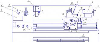
General view and placement of controls for a screw-cutting lathe mod. 16K20
| Control handles: 2 - interlocked control, 3,5,6 - setting the feed or pitch of the thread being cut, 7, 12 - controlling the spindle speed, 10 - setting the normal and increased thread pitch and for cutting multi-start threads, 11 - changing the direction of cutting - thread (left- or right-hand), 17 - movement of the upper slide, 18 - fixation of the quill, 20 - fixation of the tailstock, 21 - steering wheel for moving the quill, 23 - activation of accelerated movements of the caliper, 24 - inclusion and disengagement of the lead screw nut, 25 - control for changing the direction of rotation of the spindle and stopping it, 26 - turning on and off the feed, 28 - transverse movement of the slide, 29 - turning on the longitudinal automatic feed, 27 - button to turn on and off the main electric motor, 31 - longitudinal movement of the slide. | Machine components: 1 - bed, 4 - feed box, 8 - main drive belt drive casing, 9 - front headstock with main drive, 13 - electrical cabinet, 14 - screen, 15 - protective shield, 16 - upper slide, 1 9 - rear headstock, 22 — longitudinal movement support, 30 — apron, 32 — lead screw, 33 — bed guides |
Glossary of terms
1 (third digit in the name of the machine model) - vertical milling console type of machine according to classification.
2 (the fourth digit in the name of the machine model) is a number expressing the size of the table in width and length, equal to 320 × 1250 mm.
2.5-axis processing - control of three coordinates using two control channels, one of which is switchable.
3 (the fourth digit in the name of the machine model) is a number expressing the size of the table in width and length, equal to 400 × 1600 mm.
6 (the first digit in the name of the machine model) - milling group of metal-cutting machines according to classification.
8 (the third digit in the name of the machine model) is a horizontal milling console type of machine according to classification.
Automatic cycles are a set of automatically executed movements of machine components performed in a certain sequence.
ASI - automatic tool change.
ASUP is an automated enterprise management system.
Stepless feed control - provides any speed of movement of the working bodies in a given feed range, allowing you to accurately set the required processing modes.
Rapid movements of units - installation movements of units at a speed significantly exceeding the speed of the working feed.
Roller is a working part of a roller machine designed for grinding grain and intermediate products of grain grinding.
Roller mill is a machine for grinding grain and intermediate products.
Vertical milling machine is a milling machine with a vertical spindle.
Vertical spindle - a spindle whose axis is located vertically.
Hydraulic unloading of the console - reduction of reactions in the guides of the console when it moves by using hydraulic devices.
Hydraulic system - a hydraulic station, a set of pipelines and a working body.
A hydraulic station (hydraulic pump installation) is a device in which electrical energy is converted into the energy of a fluid moving under pressure.
Hydraulic clamping device - a clamping device that uses a hydraulic drive.
A horizontal milling machine is a milling machine with a horizontal spindle.
Horizontal spindle - a spindle whose axis is located horizontally.
A dividing head is a device on metal-cutting machines for rotating the workpiece at a certain angle.
Discreteness is the movement of a machine unit in mm per unit of control information.
A slotting head is a device for metal-cutting machines designed to perform slotting operations.
Tolerance is the difference between the largest and smallest limit sizes or the absolute value of the algebraic difference between the upper and lower deviations.
Stiffness is the ability of a structure to resist deformation.
Gap is the distance between loosely mating surfaces.
Countersinking is a technological operation for semi-finishing holes.
The bed mirror is the main plane of the bed guides.
Gear shaping is the planing of teeth with a tool in the form of a gear wheel, the contour of the end of the gear rim serves as the cutting edge.
Tooth rounding - rounding of the ends of the teeth.
Gear hobbing machines are milling machines for processing gear teeth.
Gear - a wheel with protrusions (teeth) for transmitting motion by interacting with the teeth of another link (wheel, rack, etc.)
The accuracy class of the machine is N - normal accuracy, P - increased accuracy, B - high accuracy, A - especially high accuracy, C - special accuracy.
Console is a cantilever-mounted, vertically movable machine unit that carries a work table. In engineering, this is usually called a beam fixed at one end.
A cantilever milling machine is a milling machine whose work table is located on a console.
A contour-positional system is a system that has the ability to operate both along a contour and in positioning mode.
Morse taper is a conical surface with a small cone angle for mating the tool and spindle.
Spindle taper is a conical hole in the end of the spindle used for mounting tools.
End mill - a cutter for simultaneous processing of two mutually perpendicular surfaces.
A copying machine is a machine for processing curved surfaces using a copying device.
The gearbox is a multi-link mechanism designed to change the speed of rotation of the output shaft at a constant speed of rotation of the input shaft by changing the gear ratio.
Round rotary table - a table designed for positioning or feeding by rotating around its axis.
Circular feed - feed carried out by rotational movement around the axis of the table.
Center line is an imaginary line passing through the centers of a machine tool or test fixture.
Steady rest is an additional support to avoid deflection of the workpiece.
A tool magazine is a device for storing tools.
The deceleration mechanism is a mechanism for reducing the working feed to a certain value.
Feed mechanism is a multi-link mechanism of a metal-cutting machine designed to change the speed and direction of feed.
The mechanism of proportional feed deceleration is a mechanism for reducing the working feed in proportion to its value.
Multi-operational processing is the implementation of many operations with one installation of a part.
A multi-operational machine is a machine that has one spindle and is equipped with a CNC system and a magazine for storing and changing tools.
Multi-spindle machine - a machine with several spindles.
A coupling is a device for connecting two shafts that transmits torque without changing its direction.
An overhead milling (spindle) head is a device that has its own spindle, which receives rotation from the machine spindle.
Guides are surfaces used to move one machine unit relative to another in a certain direction.
The processed surface is the surface layer of the processed material formed during cutting.
A machining center is a CNC and ASI machine designed to sequentially perform several technological operations using various tools according to a given program.
Single-spindle machines are machines with one spindle.
A mandrel is a device used for attaching workpieces or tools to it when processing on metal-cutting machines.
Axial feed is a feed carried out by moving along the axis of a tool or workpiece.
Equipment is a set of devices for performing various technological operations.
Deviation is the algebraic difference between the actual size and the nominal size.
A chuck is a device for securing workpieces or tools on metal-cutting machines.
A faceplate is a device in the form of a flange mounted on the spindle of a lathe, boring and other machines to secure the workpiece or tool being processed and transmit rotation to it.
The table plane is the working surface of the table for securing workpieces or fixtures.
A rotary milling (spindle) head is a device that has its own spindle, which receives rotation from the machine spindle and has the ability to rotate.
Table feed - moving the table when performing technological operations.
A slider is a machine unit that forms a translational pair with another unit.
Transverse stroke is a movement perpendicular to the longitudinal axis of the table.
Main motion drive is a drive that provides cutting speed (relative speed of the cutter relative to the workpiece).
Drive is a system of interconnected devices for driving one or more solid bodies that are part of a machine or mechanism, including an energy source, a mechanism for transmitting motion and control equipment.
Accessory - most often an accessory such as a vertical attachment head, slotting attachment head, dividing head and dividing table.
A device is a technological device that is attached to a machine or used independently for basing and securing a workpiece when performing technological operations.
Longitudinal milling machines are milling machines with table movement only in the longitudinal direction.
The working surface of the table is the surface of the table for installing and securing a part or device on it.
Reaming is the process of semi-finishing and finishing machining of conical and cylindrical holes with a special tool - reamers.
Marking work is work associated with applying points and lines to workpieces indicating the contours of the surfaces to be machined, as well as axial and auxiliary lines and center marks for aligning workpieces when installed on machines.
Reaming - processing by drilling a pre-drilled or cast hole.
Boring - (semi-finishing) is used when processing short, stepped and precise holes in size and shape.
A gearbox is a device for changing angular speeds and torques.
Cutting is the processing of metals by removing chips.
A cutter is usually a steel bar of rectangular, square or round cross-section, the cutting part of which has a certain geometric shape and angles. It consists of a head (carrying the cutting part) and a body (holder).
Threading work - cutting threads on the outer or inner surface of workpieces with the removal of chips.
A rack is a bar or rod with teeth, a gear element for converting rotational motion into translational motion.
Rifles are sharp grooves on any surface.
Drilling and milling machine is a metal-cutting machine for drilling and milling workpieces.
A servo-adjustable feed drive is a feed drive with a device for monitoring the speed of a moving unit and its position in real time.
SNiP - building codes and regulations.
The bed is the main part of the machine on which the working units and mechanisms are mounted.
A table is a unit of a metal-cutting machine (usually movable) for attaching a device or workpiece to it.
Carbide tool is a tool whose cutting element is made of a hard alloy (tungsten carbide, titanium carbide, etc.)
A machine vice is a device for securing a workpiece during processing.
An end mill is a cutter for processing flat surfaces, the axis of which is perpendicular to the surface being machined.
T-slot - a groove in the form of an inverted letter "T", used to secure and base a workpiece or fixture.
Universal milling machine - a milling machine for performing a variety of milling operations on various workpieces.
Controlled coordinates are the coordinates of movement of machine components along which movement is controlled.
A control program is an ordered sequence of commands that ensures the execution of a technological process.
Digital display device - a device that displays the values of controlled parameters in digital form.
Shaped hole - a hole with a shape other than round.
A shaped cutter is a cutter for processing surfaces that repeat the shape itself.
Milling (spindle) head is the part of the milling machine that carries the spindle. There are horizontal, vertical and inclined, including rotary.
Milling is processing with removal of chips using a multi-edged rotating tool - a milling cutter.
Milling trunk - a machine unit made in the form of a cantilever beam, usually used to support a mandrel with a working tool.
A journal is a part of a shaft or axle that rests on rolling or sliding bearings.
The center is a steel cone used to install the product when processing on a machine or in instrumentation.
A cylindrical cutter is a cutter for processing flat surfaces, the axis of which is parallel to the surface being processed.
Worm - the driving link of a worm or globoid gear, which is a screw that engages a worm wheel.
CNC - numerical program control.
Surface roughness is the micro-irregularities of the surface being processed.
A highly versatile milling machine is a milling machine with advanced technological capabilities.
Machine spindle - the output shaft of the machine gearbox, designed for securing workpieces or cutting tools.
Spindle mandrel is a device used for fastening and basing tools and workpieces in the spindle of metal-cutting machines.
A key is a part of a keyed connection that is installed in the grooves of two contacting parts and prevents their relative rotation or shift.
A keyway milling machine is a machine for processing keyways.
Keyway - a groove for installing a key.
Ram is a tool holder that performs reciprocating movements.
Equidistant is the trajectory of movement of the center of the cutter relative to the contour of the machined surface.
Electromagnetic clutch is a clutch controlled by an electromagnet.
Electric drive is an electric motor control system.
Prevention and repair
Daily care activities
Before starting work:
- Inspection of the machine.
- Lubricate the lead screw and shaft.
- Controlling the amount of oil.
- Switching on with checking nodes without load.
During operation:
- Switch feeds and gears only after the moving units have finally stopped.
- When working with cast iron or abrasive materials, cover the guides with thick cloth.
After the end of working hours: turn off the power supply, remove the shavings, wipe with a rag soaked in kerosene, and lubricate the open guides with oil.
Malfunctions and their elimination
| Symptoms | Cause | Correction method |
| Ovality of the part or hole being bored. | Blank runout in the cartridge. | Boring of jaws. |
| Quill play or weak fastening of the thrust headstock. | Adjusting or repairing the quill. | |
| Hole axis offset. | Misalignment of spindle shaft and tailstock. | Adjustment. Or repair with adjustment. |
| Significant cone of cylindrical parts. | Mismatch between the centers of the spindle shaft and the thrust head. | Adjustment. |
| Worn caliper or bed guides | Adjustment or repair. | |
| Dimensional instability during trimming. | Axial play of the spindle shaft. | Replacing rotation bearings. |
A slight increase in caliper clearances can be eliminated by adjusting the wedges in the transverse or upper slide guides, and the adjustment screws in the rear guide of the longitudinal slide. Then, moving the slide to the maximum distance, make sure that it moves smoothly. Leaks in the screw drive of the cross slide are eliminated by adjusting the screws located behind the tool holder platform.
Equipment Specifications
The screw cutting machine has a wide range of technical features:
- The power of the electric motor ensures the functioning of the main drive and reaches 7.5 kW. And the drive itself, responsible for moving the caliper, has a power of 0.37 kW. The electric motor for the lubrication mechanism is 0.12 kW,
- the maximum length of the workpiece to be turned is 1.46 meters, and the maximum dimensions of the product fixed in the centers of the machine are 1.5 meters,
- Automatic transmission,
- thread cutting is carried out by the worker selecting a step, which is set by him based on the type of workpiece,
- the maximum cross-section of the workpiece turned above the bed should not be more than 40 centimeters, and above the support - 21 centimeters,
- the number of revolutions of the spindle device in forward motion is from 25 to 2500 rpm, and in reverse motion – from 25 to 1250 rpm,
- in forward movement, the spindle device has 21 speed levels, and in reverse – 18,
- the machine drive is from a 2-speed electric motor together with a gearbox and a bulkhead that programs 12 degrees of spindle speed in any of the 2 ranges,
- transverse feeds vary from 0.025 to 1.4 mm, and longitudinal feeds - from 0.05 to 2.8 mm per rotation,
- The range of movement of the caliper along the screw is 75 centimeters (lengthwise) and 22 centimeters (crosswise). The maximum distance of its movement along the roller is 50 centimeters,
- Rolling bearings create rigid and high-precision support,
- The guides of the carriages and the rolling pairs of the screws have impulse automatic lubrication,
- feed drive provides stepless feed adjustment,
- loading and unloading of parts is carried out manually.
These technical parameters enable the car to enjoy popularity even 50 years from the date of its release. The letters “K” and “P” in the name of the machine indicate that there is a copying mechanism and an increased degree of accuracy, respectively. The screw cutting machine is capable of operating from a mains voltage of 220, 380, 400, 415 and 440 V. It is characterized by a modern ergonomic structure and is easy to operate and control.
Dimensions and weight of the machine
The screw cutting machine is small in size and weight for a machine with similar functionality:
- width – 1110 millimeters,
- height – 1505 millimeters,
- length – 2270 millimeters,
- weight – 2 tons.
Purpose and scope
The 16b16kp machine is intended for performing various turning operations in centers, collets or in a 3 or 4-jaw chuck, for cutting various threads with a die or tap. Unlike most other brands, such a machine is intended for more thorough turning, and therefore is not recommended for roughing. It is usually installed in small repair shops. After processing on a lathe, the products are distinguished by excellent surface cleanliness.
Design
Model 16B16KP was created on the basis of the previously produced lathe 1A616 and 16B16. Its positive characteristics are based on the design features of the lathe:
- Automatic transmission;
- smooth adjustment of cutting speed;
- high processing accuracy – precision;
- 2 busts are installed in the headstock;
- four-position tool holder with quick withdrawal mechanism;
- automatic selection of the optimal cutting mode due to the presence of an electric drive using thyristors.
Reference. The ergonomics of the machine – ease of use – have been significantly improved. The turner controlled all operations, making a minimum of movements.
Headstock:
On the right above the bed is the most complex component of the machine - the headstock. It contains nodes:
- gearbox;
- Transmission;
- spindle unit;
- splash lubrication system.
The oil simultaneously lubricates and cools the gears, washing away dirt and metal dust from them.
Important! The bearings are filled with grease during each maintenance inspection.
Guitar:
The gears located at the ends of the shaft and screw are located inside the headstock housing and are covered with a cover. Driven by V-belt transmission. The set of gears depends on the type of thread being cut.
Reference. When the guitar cover is opened while the machine is running, a lock is activated.
Caliper:
The support moves along the machine along the bed guides. It has mechanical driving modes: working and accelerated idle. On the apron there are handles for mechanical movement and manual supply of tools.
The slide with the tool holder moves along guides in the longitudinal and transverse directions. The simultaneous activation of feeds in 2 perpendicular axes is blocked by a device on the control handle.
Tailstock:
Located on the right side of the bed. It is attached to the guides with clamping strips and screws. A quill is installed inside the body, in the same axis with the spindle. It is moved manually by a handwheel located at the rear and clamped using a handle.
Morse quill cone No. 2. It states:
- center;
- drill;
- countersink;
- tap for cutting internal threads.
The tailstock moves along the guides manually. Fixed in place by straps located underneath. They are brought into working condition by a lever.
During adjustment, the quill is adjusted coaxially with the spindle using adjusting screws. The permissible displacement is less than 0.01 mm.
Apron:
The machine's running shaft and screw pass through the apron. Cam clutches with bevel gears convert torque into forward motion: forward and reverse motion of the caliper and carriage.
On the apron there are handles for controlling the caliper, slide, and switching cutting modes. The amount of displacement of the tool relative to the part is calculated from the divisions of the dial and vernier with an accuracy of 0.1 mm.
The movement of the caliper and slide forward and backward is started using the joystick. Its unit is equipped with a device for blocking the simultaneous activation of the working stroke in different directions. When you press the button in its handle, high speed is activated.
On the sides of the apron, above the guide, limit switches are installed. Having reached the extreme point, they are triggered and stop the caliper.
Gearbox:
The precise pitch when cutting threads is ensured by the lead screw. Its rotation, associated with a certain ratio with the revolutions of the part, is ensured by the feed box. It is located at the rear and rises above the headstock.
Transmission:
The gearbox is located at the bottom of the headstock, under the spindle assembly. It transmits torque to the drive shaft of the feed box.
Gearbox:
The automatic transmission is located at the rear of the headstock. She rotates the spindle. The presence in it of two searches: 1:4 and 1:16 increases the choice of the number of revolutions of the workpiece.
Principle of operation:
When you press the "Start" button, the engine is turned on. Through cam clutches, torque is transmitted to the drive shaft of the gearbox. It drives the lead screw through the feed box.
The spindle is driven through an automatic gearbox that transmits rotation from the output shaft of the gearbox. The speed of its rotation is controlled by a knob on the headstock. She, in turn, switches the gears of the search.
Cam clutches installed in the apron transmit movement to the caliper. At the same time, the tool holder with the tool moves with it.
DEVICE AND TECHNICAL DESCRIPTION OF MODERN SCREW-CUTTING LATHES
A lathe consists of a bed, a headstock - gearbox, a guitar, a feedbox, a support with a tool holder and a tailstock.
The lathe bed is made of high-quality cast iron or Mechanit material, which reduces vibration and resonance of the bed and reduces crushing in various cutting modes. The width of the bed is an indicator of the rigidity of the base element of the machine - the wider the bed, the better. The sliding guides of the frame are hardened and ground; for high-precision machines, the guides are additionally subjected to scraping. The frame has a recess for installing a coolant pump.
The spindle headstock is designed to rotate the workpiece being processed together with the spindle, as well as for the turner to switch the spindle rotation speeds (by special order, the machine can be equipped with stepless switching of the headstock speeds - thanks to the use of frequency regulation on the main drive). The spindle can be double-supported or three-supported. To rotate the spindle, high-class bearings are used with the ability to adjust the backlash. A lathe chuck is attached to the spindle with a conical fit for clamping the workpiece. The chuck is clamped manually by a turner using a special key (on special order, the machine can be equipped with a pneumatic clamp or a hydraulic jaw clamp). Headstock lubrication is centralized. The position of the headstock relative to the bed is adjusted with special screws - with the help of them a minimum taper is achieved. Spindle rotation and braking are provided by the friction clutch (clutch) control mechanism of the main drive. Special modifications of lathes use hydraulically driven clutches. The electrical cabinet of the machine control system is usually mounted at the rear of the headstock.
From the spindle head to the feed box, rotation is transmitted through replaceable guitar gears, which allow you to configure special caliper feeds and threading on the machine. The adjustment of replacement gears is carried out by a turner. A running shaft and a threaded screw come out of the feed box, and by their rotation they transmit movement to the caliper apron.
The support is designed to provide longitudinal and transverse movement of the cutter at operating speed (feed speed) or at accelerated speed for installation movements of the support (accelerated speed). The support consists of an apron, lower slide - carriage, cross slide, rotary part and tool holder. The tool holder is fixed in 4 positions. The uterine nut on the apron is turned on with a special handle. For high-precision machine tools, the slide guides of the caliper are coated with a special anti-friction material to eliminate the sticking effect at low feed speeds. Also, to increase accuracy and reduce backlash in the transverse stroke, a ballscrew is used instead of a SCREW-NUT transmission. To select the feed direction, mechanical jaw clutches or electrical multi-disc clutches (electric clutches) are used. The caliper moves along the frame thanks to a mechanism - rack and rack pin. To separate the working and accelerated speeds, an overrunning clutch is used in the apron.
Cutting slide - rotating - rotation angle +/-90 degrees. The twist is used to process short cones. The cutting slides have manual or mechanical movement (mechanical drive of the upper cutting slides).
The tailstock is designed to support and process parts in centers or for drilling parts (as well as threading, countersinking, reaming). The tailstock moves along the machine along the bed guides. By rotating the tailstock steering wheel, the quill moves out of the tailstock body or pushes it back. The tailstock quill is fixed motionless with a special handle. The diameter of the quill determines the rigidity of the machine when processing in centers. Special adjustment bolts allow you to adjust the position of the center of the tailstock in the horizontal plane for lateral displacement of the tailstock body. The conical hole in the quill is Morse No. 6 (reinforced) or No. 5 (regular). The main parameters of the tailstock: the largest movement of the quill and the price of one division of the quill movement dial. Thanks to the transverse displacement of the tailstock housing, it is possible to machine cones on the machine.