Argon arc welding of bronze
Argon arc welding of bronze is carried out in the event of detection of casting defects or the formation of defects during surfacing and in other cases. Bronze parts are welded with preheating to approximately 350 - 400 degrees Celsius. Large products are heated to 500 - 600 degrees. The strength of bronze at high temperatures decreases significantly , so the part must be well secured before welding so that it is not accidentally damaged during the welding process.
After welding, bronze parts are annealed and heated to 700 degrees. The parts are kept at this temperature for 3 to 5 hours. Heating of castings begins at a temperature of 200 degrees, and the temperature rises by approximately 100 degrees per hour. For castings that perform critical tasks, temperatures up to 750 degrees Celsius are used. Rolled bronze is cold forged. This is done to increase the density and strength of the weld metal.
When welding with carbon electrodes, direct current of straight polarity is used. To weld tin bronze, rods are used that contain 8% zinc, 3% tin, 0.2 phosphorus, 0.3% nickel, 0.3% iron, 0.2% lead. The remaining material is copper. For other types of bronzes, rods of the same composition that make up the main metal being welded are used.
Bronze welding is widely used . The best welding results are obtained by welding with direct current of reverse polarity. The welding current is 30 - 40 Amperes per 1 millimeter of welding electrode diameter. If alternating current is used when welding, then in order to increase the stability of the arc, it is necessary to increase the current strength to 75 - 80 Amperes per 1 millimeter of electrode diameter. Also in such a situation, you can use an oscillator.
Welding of bronze is carried out without interruption in one layer . When welding, the electrode must be almost perpendicular to the surface of the metal. In order to better remove gases from the surface of the weld, zigzag movements are made. In order to obtain the maximum soldering height, it is necessary to conduct an arc with preliminary shaping of the welding site at an inclination of up to 15 degrees to the horizontal position. If welding is carried out without heating, then a larger welding current is used for this work.
If the bronze was welded in accordance with the requirements, then the mechanical properties of the weld are approximately the same as the properties of the base metal. For rolled bronzes, argon welding is used using non-consumable electrodes, such as tungsten.
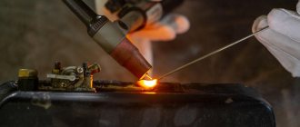
Bronze is often welded using gas welding. In this case, welding is carried out with the part heated to 450 degrees Celsius. The welding flame must be reducing, because if it has oxidizing properties, the content of tin, aluminum and silicon will be greatly reduced.
Aluminum welding technology
Aluminum is one of the most common natural elements. It is distinguished by its resistance to becoming brittle at low temperatures, high corrosion resistance in oxidizing environments, high thermal and electrical conductivity, and low density.
Its melting point is +660 °C, and its density is 2.7 g/cm3. Aluminum is always coated with a film of aluminum oxide (Al2O3) due to its high affinity for oxygen. The melting point of this film is +2050 °C. The main difficulties encountered when working with aluminum are due to the refractoriness of the film and the risk of crystallization cracks and pores in the weld.
The aforementioned aluminum oxide film prevents the weld pool metal from fusing with the base metal. Therefore, it is removed with metal electrodes for welding non-ferrous metals, affecting the electrode coating or flux components. In argon arc welding, the film is destroyed by cathode sputtering. If you use direct current of reverse polarity, it has a “cleaning” effect throughout the entire arc burning time. And alternating current acts in this way only during those half-cycles when the product is the cathode.
Pores in welds are formed due to hydrogen, which strives to escape into the atmosphere due to a sharp change in solubility when aluminum transitions from a liquid to a solid state. And crystallization cracks appear due to the increased silicon content. To reduce them, iron additives are introduced into aluminum.
Manual welding with carbon electrode. It is performed in cases where the thickness of non-ferrous metal is from 1.5 mm to 20 mm, as well as when welding defects in castings made of aluminum and its alloys. If the thickness of the non-ferrous metal does not exceed 2 mm, then it is welded without cutting the edge and filler wire.
Manual arc welding with a metal electrode. To work with products made of pure aluminum (“AD”, “AD1”, “ADO”, “A6”), “AF-4aKr” and “OZA-1” electrodes are used.
Manual arc welding of non-ferrous metals is carried out with direct current of reverse polarity after preheating the sheets being welded: 6-8 mm thick - at temperatures up to +200 °C, 8-16 mm - up to +350...+400 °C.
Before starting work, the electrodes should be dried for two hours at a temperature of +150...+200 °C. If the thickness of non-ferrous metal is more than 20 mm, then the edges must be cut. Welding is performed on both sides with a gap between the sheets of 0.5–1 mm.
“A-2” electrodes are used to eliminate defective areas in the casting of the “AL-9” alloy and welding of the “AMts” type aluminum-manganese alloy. The product should be preheated (“AL-9” to +280…+300 °C, “AMts” - to +300…+400 °C) with a short arc of direct current of reverse polarity.
Electrodes "ОЗА-2" are used for welding alloys "AL-11", "AL-9", "AL-5", "AL-4", "AL-2", which is performed after preheating the area to +250... +400 °C short arc and direct current of reverse polarity.
Automatic and semi-automatic flux welding is used for products whose edge thickness exceeds 8 mm. In this case, the arc burns above the flux, and not in its layer. A thin layer of flux is sufficient to remove the oxide film and protect the weld pool. If the thickness of the flux layer is large, then the arc is shunted through the slag, which has high electrical conductivity, and burns along the flux layer.
When welding non-ferrous metals semi-automatically, electrode wire of the SvAMts or SvA97 brand with a diameter of 2-3 mm is used. Flux “AN-A1” (20% sodium chloride, 30% cryolite, 50% potassium chloride) is applied to the seam to be welded in a layer 10–35 mm thick. The work is performed by direct current of reverse polarity. Its speed will be approximately 12–20 m/h with the following parameters: welding current – 300–450 A, electrode extension – 25–40 mm, arc voltage within 38–44 V.
Argon arc welding of aluminum and its alloys has become most widespread. When using it, there is no need to use relatively complex fluxes and coatings, the remains of which can cause corrosion of the weld. In this case, they work with direct current of reverse polarity or alternating current, but always with an oscillator and a ballast rheostat.
Automatic and semi-automatic welding of non-ferrous metal in an argon environment with a consumable electrode is performed with special semi-automatic hose machines and automatic machines. The work uses direct current, selects the appropriate welding mode and applies reverse polarity. In this case, welding wire “SvA97”, “SvAMts”, “SvAK” or the same composition as the non-ferrous metal being welded is suitable.
A section of a part up to 10 mm thick is welded without cutting the edges; for large edge thicknesses, V- and X-shaped seam grooves are used. The current strength with an electrode wire with a diameter of 2 mm is 250–300 A, the operating speed reaches 30–40 m/h.
Gas welding of aluminum products will give excellent results if you use fluxes correctly and choose the appropriate mode. Sheets with a thickness of no more than 3 mm should be welded with flanged edges to a height equal to triple their thickness. And sheets with a thickness of no more than 5 mm are welded without beveling the edges, with a gap of up to 0.5 mm.
Sheets with a thickness of 5–15 mm are welded with a one-sided bevel of the edges, with a larger thickness - with a double-sided bevel. The cutting angle is 60–70°. It is not recommended to weld lap joints because flux flows into the gap between the sheets and causes corrosion, which causes the seam to fail. The filler wire and joint edges must be thoroughly cleaned of the oxide film by chemical or mechanical means.
Mechanical cleaning involves degreasing in an alkaline solution and subsequent cleaning with a wire brush. In this case, gas welding of non-ferrous metals and alloys must begin no later than after 2 hours.
When performing chemical cleaning, strictly follow the sequence: first degrease the edges and pickle them in a 5% solution of caustic soda, then rinse with water, wipe dry with a rag and dry. Proceed to work no later than 8 hours after such cleaning.
If you are using flux in paste form, apply it to the filler wire and the edges being welded. And powdered flux should be poured into the groove of the seam. Be sure to store fluxes in sealed containers to prevent moisture from being absorbed from the air. Weld the part using the “left” method using a normal flame or with a slight excess of acetylene. But keep in mind that too much acetylene leads to the appearance of pores in the weld. The most dangerous thing is excess oxygen. It intensively oxidizes aluminum, significantly complicating work. During the first time of welding, tilt the torch mouthpiece at an angle of 70–80°, and then reduce it to 30–45°.
Depending on the thickness of the non-ferrous metal, the appropriate power of the welding flame is selected:
Before welding silumins, preheat the part to +200…+250 °C. After this, anneal at a temperature of +300...+350 °C and slowly cool it. Forge the seams of welded joints made of rolled steel in a cold state with light blows. Thoroughly remove any remaining flux and slag with a wire brush and rinse with hot water.
How bronze welding is performed, what techniques exist
Bronze has become very popular among materials. But the difficulties that arise during welding work significantly spoil the whole picture. Many people understand that bronze is not a chemical element, but an alloy, but not everyone knows that the composition of the material can be different.
In a general sense, bronzes mean copper alloys to which alloying elements such as aluminum, tin, silicon or manganese have been added.
Let us immediately note that in a number of physical properties bronze is similar to brass. In particular, identical welding methods are defined for these materials. In metallurgy, there is a clear division of alloys. If copper and zinc are used as the main element, the resulting alloy is called brass.
Types of bronze are determined depending on which element is used for alloying. In the simplest classification, bronze can be divided into tin and tin-free. Tin bronze in its composition, in addition to copper and tin, can contain nickel, phosphorus, and zinc. It is believed that it is the addition of tin to the alloy that makes it of higher quality.
Welding brass with argon - solving difficulties together
Sometimes you have to deal with tasks such as welding brass with argon on one scale or another. Brass itself, like most other non-ferrous metals, is quite difficult to weld. Therefore, if you are not involved in this, or if this is the first time you need to weld a damaged part, or complete a specific order, you will have to first familiarize yourself with the problems and features of the welding technique for this metal.
Issues
Brass is a metal that is a binary or multicomponent alloy based on copper, in which the main alloying component is zinc; lead, tin, manganese, nickel, and iron can be partially added. Due to its properties, brass is difficult to weld, as it changes its physical properties when rapidly heated and subsequently cooled. For example, the strength of a welded joint is strongly influenced by such factors as - the presence of zinc; — presence of hydrogen in the oxide film.
In the first case, Zn evaporates under the influence of high temperatures (it is known that zinc evaporates already at 420 degrees, and boils at 907 degrees, which coincides with the melting point of brass), due to which dangerous vapors are released, and brass acquires poor ductility . In the second, due to hydrogen, the welding seam is saturated with bubbles and, as a consequence, its weak strength.
blog.svarcom.net
Peculiarities
Often, when cooking tin bronze, a phenomenon such as the formation of frozen drops is observed. This happens for the reason that fusible fractions float to the surface. Components such as lead and zinc are subject to waste. Their boiling point is lower than that of copper, so natural evaporation occurs.
The type of flame should be controlled. It must be strictly normal. An oxidizing flame burns out the tin, and a carburizing flame causes pores to appear. Acetylene consumption during gas welding should be 70-120 liters per hour per 1 mm of metal sheet thickness. The surface must be in the reduction flame zone, which is 7-10 mm. This is the only way to reduce the degree of tin burnout.
It is recommended to preheat cast bronze parts to a temperature of 450°C degrees. The filler material is BrOTs4-3 or BrOF6.5-0.15 wire. Difficulties in welding aluminum bronze are associated with the formation of an oxide film, which has a high melting point. It can only be dealt with with a special flux. The latter is a substance containing sodium fluoride, sodium chloride, barium chloride and potassium chloride. Silicon bronze, unlike other types of alloys, is weldable well due to the presence of elements such as silicon and manganese.
There are features characteristic of any alloy containing copper. The welder must be aware of these features, because he will certainly encounter certain difficulties. The presence of copper in an alloy determines its physical properties. The thermal conductivity of bronze, like brass, is quite high, as a result of which intensive heat transfer must be taken into account. Rapid crystallization is accompanied by the formation of cracks. Another factor influences here - a high coefficient of thermal expansion. When a metal crystallizes, it “contracts”, resulting in internal stresses.
Bronze is widely used by artists and sculptors in the manufacture of busts or monuments. It is used to make fittings and decorative elements. Welding work must provide not only a reliable connection, but also an aesthetic appearance. The presence of elements such as zinc, tin or lead in alloys largely determines the characteristics of welding work.
The burnout of the listed elements is due to a significant difference in boiling points. After the metal melts in the weld pool, atmospheric oxygen is absorbed. Alloying elements react with it. A film forms on the surface of the bath. At the same time, hydrogen enters the metal, and during crystallization, pores remain. They significantly reduce the quality of the weld.
Some problems can be solved by protecting the bath with inert gas. Argon is most often used. All of the above indicates that bronze welding is a rather complex process, so the welder must have certain knowledge and experience.
PROPERTIES OF COPPER AND BRONZE CONNECTION WITH STEEL
In table 13 shows the mechanical properties of the surfacing metal obtained by conducting the process without melting the steel (plasma jet), with small penetration (argo-arc surfacing) and with significant penetration (automatic surfacing under a layer of flux). The tensile strength for all three surfacing methods is approximately the same, the yield strength is the lowest when surfacing with a plasma jet, and the relative elongation and relative contraction are maximum when surfacing with a plasma jet, significantly lower when surfacing manually using an argon-arc method and very small when surfacing automatically under a layer of flux. . This difference in the plastic properties of the surfacing metal is explained by the different amount of iron in the surfacing metal: the less iron in the surfacing metal, the higher the plastic properties with approximately the same strength properties.
The degree of melting of the base metal affects the mechanical properties of the joint to the same extent (Table 14).
The adhesion strength of the surfacing metal to the base metal was checked by testing special samples for shear, extrusion, tearing, as well as testing samples for bending both by surfacing inwards and by surfacing outwards. The test results are given in table. 14.
| Results of mechanical tests of joints during surfacing Mechanical | test properties | |||||||
| Surfacing method | Brand | Brand floating | ' adhesion strength of the surfacing metal to the base metal | to bend in hail | Litera | |||
| main metal | my metal | for cutting | for extrusion | on the break | floating whoa outward | floating whoa inside | tour source | |
| kgf/mm2 | — | |||||||
| Automatic under layer | 09G2 | Br. KMtsZ-1 | _ | _ | _ | 30^60 | _ | Author |
| flux wire | 47 | |||||||
| Recumbent electrode | 09G2 | MZS | 18,8—26,1 | — | — | — | — | » |
| 22,6 | ||||||||
| Manual argon-arc | Art. Z | Like | 32,8—44,3 | — | 47,8—53,9 | 26—145 | 180 | » |
| in the right way | MNZH5-1 | 37,6 | 49,2 | 73 | ||||
| Double independent | 09G2 | Br. KMtsZ-1 | 17,5—27,5 | 15,7—30,2 | — | — | — | » |
| arc | 23,8 | 23,0 | ||||||
| Plasma jet | Art. Z | Like | 31,7—35,2 | 31,5—35,8 | 34,1—34,6 | 180 | 180 | » |
| MNZH5-1 | 33,4 | 33,6 | 34,4 | |||||
| Friction | 20 | Br. AZh9-4 | — | — | 30 | — | — | [39] |
| Gas | Art. Z | Ml | — | 13,4—15,7 | — | — | — | [59] |
| 14,6 | ||||||||
| » | Art. Z | L62 | — | 31,0—40,0 | , — | — | — | [59] |
| 36,0 |
As can be seen, the adhesion strength of the surfacing metal to the base metal is either at the level of the strength of the deposited metal itself (when surfacing without melting steel) or slightly higher than the strength of the deposited metal (in the case of surfacing with melting steel or even when surfacing without melting steel, but with a significant dissolution of the surfacing in the liquid metal and the formation of a developed zone of variable composition). In the first case, destruction occurs directly along the fusion boundary of the surfacing metal with the base metal (Fig. 46, 47, a), during
| Rice. 46. Sample after testing for extrusion of the deposited layer obtained by surfacing bronze type MNZh5-1 on steel Art. Z. plasma- |
in the second case, as can be seen from Fig. 47, b, destruction occurs at some distance from the fusion boundary. Strengthening of the surfacing metal in the transition layer in the second case is ensured by the transition of iron from the base metal to the surfacing metal.
Tensile tests of flat and round samples obtained by surfacing bronzes of the MNZh5-1 and Br types. KMtsZ-1 on low-carbon steels using both a plasma jet and the argon-arc method with a non-consumable and consumable electrode, showed that the strength of such a connection depends mainly on the thickness of the surfacing metal layer: the greater the thickness of the surfacing metal layer, the lower the strength of the connection, since the strength of the _____ deposited metal itself is lower than the strength of the steel filler wire. So, in a tensile test
For round samples obtained by surfacing bronze type MNZh5-1 onto steel 20, the ultimate strength values were obtained: o = 45 - 47 kgf/mm^ both when surfacing with a plasma jet and during argon-arc surfacing with a non-consumable electrode. Sample dimensions: steel rod diameter 18 mm, deposited sample diameter after machining 21 mm. The strength of the steel itself is hell = 50.2 kgf/mm2. However, the bending angle is consistently 180° only when surfacing without melting the steel (plasma jet), and when surfacing automatically under a layer of flux, the bending angle is only 30–60° (Table 14).
Fatigue limit of the joint obtained by plasma surfacing of bronze Br. KMtsZ-1 on steel 09G2 with a symmetrical tension-compression cycle (g = -1) based on 5-10® cycles is about 13.0 kgf/mm2 when testing flat samples, while with automatic surfacing under a layer of flux, the endurance limit according to the data N.N. Plishkina [73] is only
6.5 kgf/mm2.
Thus, the required adhesion strength of the surfacing metal to the base metal and the static strength of the deposited joint are ensured by almost all surfacing methods. Optimal plastic properties of a joint can be stably ensured only when surfacing without melting the steel (for example, when surfacing with a plasma jet). Such a decrease in the plastic properties and endurance limit of the connection
Rice. 47. Samples after testing for separation of the deposited layer from the base metal when surfacing with MNZh5-1 type wire on steel » St. Z: a - without melting steel (plasma surfacing); b - with a slight melting of steel (argon-arc surfacing with a non-consumable electrode) |
In our opinion, the differences during surfacing with melting of steel can be explained by the presence of a developed zone of structural and chemical heterogeneity of the weld metal.
One of the reasons for the decrease in fatigue strength and ductility of joints of dissimilar metals copper-steel during welding (surfacing) with melting of the base metal is that in the resulting mixed layer during the cooling process, due to the limited mutual solubility of iron with copper, the decomposition of solid solutions of iron-copper or iron-nickel-copper. This decay is accompanied by the appearance of new phases in the early stages of aging [63].
The decomposition of the Fe–Ni–Cu alloy was studied in [3, 72]. In [3] it is shown that during the decomposition of the Fe-Ni-Cu alloy, stresses of the second and third kind arise. From work [72] it follows that the process of decomposition of the Fe-Ni-Cu alloy is accompanied by the appearance of significant stresses of the second kind (up to 2.3-10"3 cm)
and the formation of small mosaic blocks (1-1.5 ■ 10-6 cm). The authors of [72] believe that the effect of block dispersion is not due to the crushing of large mosaic blocks as a result of the occurrence of significant stresses, but to the appearance of the 7X and 72 phases (the alloy stratifies into two phases during the decomposition process). As a result of the redistribution of components among the phases in the Fe-Ni-Cu alloy during phase separation, distortions of the second kind reach their maximum value.
During the decomposition of the Cu-Fe alloy, it was discovered [114] that after plastic deformation, not the intermediate 7-phase, but a stable a-phase, is released from the solid solution, without the preliminary formation of the 7-phase. In the presence of such significant stresses in the transition zone, it is difficult to expect high plastic properties and a high endurance limit.
The existence of such heterogeneity has been shown by metallographic studies; it is also revealed when examining the hardness of the metal of the joint. Hardness was measured on a Vickers device at a load of 5 and 10 kgf. The research results are given in table. 15. As the above data show, the hardness of the surfacing metal increases with increasing iron content in it. The hardness of the transition zone metal especially increases both on the side of the surfacing metal and on the steel side, which characterizes the chemical and structural heterogeneity of this zone during surfacing with melting of steel. Only plasma surfacing at optimal conditions ensures sufficient uniformity both over the cross-section of the surfacing metal and in the steel, which ensures high plastic and fatigue properties of the deposited joint.
Thus, the results of studies of the mechanical properties of the surfacing metal and deposited joints when surfacing copper and bronze on steel show that optimal properties can only be obtained by surfacing without melting the base metal and with a minimum duration of contact between the solid and liquid phases, i.e. with plasma surfacing at optimal conditions.
In a number of cases, when assessing the properties of deposited products, the corrosion resistance of the deposited metal is of decisive importance. As mentioned above, the corrosion resistance of the surfacing metal can be judged by the quantitative iron content and the structure of the surfacing metal. For verification, additional corrosion tests were carried out using the following method:
1) qualitative testing of the corrosion resistance of the surfacing metal depending on its iron content in order to detect traces of local corrosion;
2) in the absence of local corrosion, a quantitative check of uniform corrosion was carried out;
| Hardness of metal joints during surfacing Hardness HV | |||||||||
| Surfacing method | Basic metal | Weld metal | Iron content in metal | surfacing metal | base metal | ||||
| surfacing | |||||||||
| • | at the fusion boundary | after 0.5 mm | far from the fusion boundary | at the fusion boundary | after 0.5 mm | in original condition | |||
| 0,17—0,21 | 90,6— 99,0 | 91,7— 99,0 | 88,3— 92,9 | 164—181 | 164—175 | 162—172 | |||
| Steel | Br. KMtsZ-1 | 0,45—0,72 | 101—116 | 107—120 | 85—91 | 157—164 | 157—166 | 159—164 | |
| 09G2 | |||||||||
| 0,8—0,92 | 101—122 | 107—124 | — 90—107 | 166—179 | 157—175 | 159—168 | |||
| Plasma jet with | 1,75—2,3 | 98—120 | 104—135 | 100—116 | 166—191 | 164—179 | 164—175 | ||
| current-carrying additive | |||||||||
| no wire | Art. Z | Like | 1,5—2,0 | 115—127 | 116—137 | 118—129 | 133—141 | 133—139 | 133—141 |
| MNZH5-1 | |||||||||
| 0,4—0,51 | 106—127 | 107—124 | 104—105 | 206—218 | 209—227 | 212—224 | |||
| 1Х18Н9Т | Br. KMtsZ-1 | ||||||||
| 0,52—0,57 | 125—135 | 125—135 | 116—123 | 183—201 | 181—198 | 183—201 | |||
| Argon-arc ' not | Art. Z | Like | 9—12 | 148—286 | 150—245 | 185—245 | 185—223 | 133—141 | |
| consumable electrode | MNZH5-1 |
3) checking corrosion resistance on a standard pipeline unit, sections of which are connected by flanges and rings to a surface deposited with Br bronze. KMtsZ-1 double independent arc.
To carry out corrosion tests, rings were deposited with a double independent arc and a plasma jet with a current-carrying filler wire. The surfacing modes were selected so that the iron content in the surfacing metal ranged from 0.52 to 3%. Surfacing was carried out using bronze wire Br. KMtsZ-1 02 mm on the SKS-1 machine, modernized for these purposes, and on a specially manufactured machine for surfacing flanges and rings. Disks were made from the deposited rings by removing chips from the steel side to the deposited metal and processing the deposited surface.
To carry out corrosion tests, an installation was made consisting of a tank with synthetic sea water of the composition: water + 3% table salt. The installation shaft is horizontal (for the possibility of installing disks), it is connected to a motor that provides a shaft rotation speed of 1450 rpm. Samples for corrosion tests, pre-weighed, were installed on the shaft of the corrosion installation and isolated from one another with rubber or wooden gaskets. So much synthetic sea water was poured in that half of the disk was in water, and the other half was in contact with air. Due to the high number of revolutions of the disk, its upper half is covered with a thin film of entrained aerated water and is in “foam”, which completely fills the entire part of the installation that is not occupied by water. As a result, individual sections of the disks are alternately located either in water or in an environment intensely saturated with air, due to which the aggressiveness of the environment increases. After the rotation period had expired, the samples were removed, cleaned of corrosion products and weighed.
It should be noted that simultaneously with the disks made of surfacing metal, disks made of pure copper and MNZh5-1 alloy were manufactured and passed the same test. The corrosion resistance of the disks was assessed on a scale for copper and its alloys in accordance with GOST 5272-50. The results of corrosion tests are given in table. 16, in which the contact area is calculated without taking into account the area of the end surface of the disks.
To obtain the corrosion indicator (in mm/year), a recalculation was made using the following formula [40]:
p — 8'76K
where P is permeability in mm/year
K is the weight loss of the metal in g/m2-h; y: is the specific gravity of the test metal in g/cm3.
| Results of corrosion tests of surfacing metal Iron content V % | Test time in h | Contact surface in m2 | Absolute weight loss in g | Corrosion rate in mm/year | Test score | ||||
| Rotation disks | Being in calm water | Total test time | considering only 1 rotation time | taking into account total time | taking into account only the rotation time | taking into account sum - : marin time | |||
| 1,2-1,8 | 690 | 2532 | 3222 | 0,03458 | 2,1922 | 0,0950 | 0,00205 | 5 | 2 |
| 0,72—0,85 | 690 | 2532 | 3222 | 0,01152 | 2,2247 | 0,2970 | 0,062 | 6 | 5 |
| 0,52 | 690 | 2532 | 3222 | 0,02856 | 3,2710 | 0,1740 | 0,0371 | 6 | 4 |
| 1,31—1,67 | 690 | 2532 | 3222 | 0,01762 | 0,8586 | 0,9796 | 0,0158 | 7 | 4 |
| 2,7—2,8 | 690 | 2532 | 3222 | 0,02516 | 2,5985 | 0,1508 | 0,0333 | 6 | 4 |
| 2,05—2,5 | 690 | 2532 | 3222 | 0,02938 | 2,9715 | 0,153 | 0,0329 | 6 | 4 |
| MNZH5-1 | 690 | 2532 | 3222 | 0,01252 | 3,6285 | 0,0433 | 0,00925 | 4 | 3 |
| MZR | 690 | 2532 | 3222 | 0,01004 | 1,2397 | 0,184 | 0,03952 | 6 | 4 |
In table Figure 16 shows the results of calculations of weight loss during testing, both taking into account only the time of rotation of the disks, and taking into account the total time the disks were in synthetic sea water (i.e., both during rotation and in a quiet state).
Analysis of the results of corrosion tests given in table. 16 shows that the disks can be classified as resistant. The test results can be considered quite satisfactory when compared with the corrosion rate of a pure copper disk. For comparison, we can cite the results of corrosion tests of copper and its alloys according to V.N. Dyatlova: the corrosion rate of copper is 0.0055 g/m2-h or 0.006 mm/year when tested in stationary distilled water at 20 ° C, 0.015 g/ m2-h (0.014 mm/year) when tested in distilled tap water, 0.02 g/m2-h when tested in synthetic sea water at a temperature of 20 ° C for 720 hours and 0.04 g/m2-h when tested in synthetic sea water at a temperature of 40 ° C for 720 hours, the corrosion rate of silicon bronze is 0.05 g/m2-h. and brass, respectively, 0.03 g/m2-h.
Some of the disks were tested for 550 hours with rotation at . shaft of the installation and was in calm synthetic water for 1980 hours. After
At the end of the test, the disks were carefully inspected. Traces of corrosion were found only on two disks in the pores that previously existed on the surface of the surfacing metal. A metallographic examination of the surfacing metal after corrosion tests was also carried out. No changes in the structure of the surfacing metal were detected.
For full-scale testing, standard pipelines were made from copper pipes connected to each other by flanges and rings with a surface deposited with Br bronze. K.MtsZ-1 with a double independent arc in a nitrogen environment. The speed of movement of sea water in the pipeline is 2 m/sec. The composition of sea water is 1800 mg of chlorides in 1 liter of water. One pipeline with welded flanges was continuously tested for 1752 hours, the other for 4500 hours. After testing, no traces of corrosion were found on the flanges.
Thus, the test results showed the high corrosion resistance of the Br bronze surfacing metal. KMtsZ-1 on steel even when the surfacing metal contains up to 1.5-2% iron, but in the form of a supersaturated solid solution or in the form of fine particles.
Preparing for work
Today, welding of bronze, like other alloys containing copper, is carried out in three ways: manual arc welding, argon arc welding and gas welding. Preparatory work is defined for each type of work and does not depend on the choice of welding method. The need to prepare metal surfaces is dictated by the requirements for the weld.
First of all, by mechanical processing it is necessary to form edges that will adjoin each other with the maximum area. Then, using sandpaper or any abrasive tool, you will have to polish the ends until a characteristic golden shine appears. This procedure must be performed in any case, since bronze is quickly covered with a layer of oxide, which can prevent the formation of a high-quality seam.
If it is not possible to carry out mechanical treatment, and the edges are in normal condition, then you can get rid of the oxide using a solution of nitric or hydrochloric acid.
Manual arc welding
Bronze welding is most often necessary when carrying out repair work, correcting defects or when surfacing. You can use preheating of the part to 350-450°C degrees, but it should be remembered that at high temperatures the strength of bronze decreases. Manual arc welding is carried out in the lower position. Metal or carbon electrodes are used as consumables.
- When using a metal electrode, a constant welding current of reverse polarity is set.
- Carbon electrodes require straight polarity.
Welding with alternating current is also possible, but for a stable arc the current strength must be significantly higher. If with direct current it is selected based on the calculation of 40 A per 1 mm (electrode diameter), then for alternating current the figure increases to 80 A. The seam is applied continuously, without transverse movements of the electrode.
Diffusion welding
Diffusion welding is the process of producing a permanent welded joint due to the diffusion (incorporation) of atoms of one metal (usually softer) into the crystal lattice of another (harder).
Thus, it is possible to obtain strong permanent connections of dissimilar metals (bimetal), as well as non-metals (for example, ceramics with glass). The method was invented in the 53rd N.F. Kazakov and is still widely used, in particular in the production of hydraulic motors for aircraft. It can also be used in other areas, especially where it is necessary to obtain precision friction pairs, and parts and assemblies are assembled using antifriction materials and operate at high speeds. An example of such a pair is the connection of tin-lead-nickel bronze BrOSN-10-2-3 with steel 30Х3ВА - it is used in the cylinder block of an aircraft plunger pump.
Argon-arc
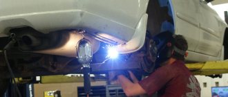
This type of welding is fundamentally similar to manual arc welding. The only difference is that the process occurs in a protective gas environment. Argon is heavier than air, so it forms a protective zone through which atmospheric oxygen does not enter the weld pool. Argon arc welding can be carried out with non-consumable tungsten electrodes or consumable electrodes, the role of which is played by rods.
It is argon arc welding that is most often used when working with bronze and brass. This preference is especially given when the metal thickness exceeds 5 mm. Welding productivity is quite high, but the process itself requires the welder to have certain qualifications. An electric arc formed between the metal surface and the electrode partially melts the edges, after which a connection occurs to form a seam. As mentioned above, preliminary preparation of the edges is required.
There are a number of recommendations that allow you to obtain high-quality connections between parts made of copper alloys.
- It is advisable to form the seam in small sections.
- When the process is finalized, the voltage gradually decreases, and then the arc is moved to the side.
- To prevent evaporation of alloying elements, special additives containing silicon, aluminum or boron are used.
Welding bronze and brass is accompanied by the release of toxic substances, so it is carried out in compliance with all possible safety measures. Argon welding has a number of advantages over other types of joints.
- Obtaining an aesthetic seam.
- Economical process.
- There is no need to clean the part from slag.
- For bronze, argon welding is the most preferable.
- Argon welding can be used to fuse parts, restoring their previous shape (for example, when worn).
- It is possible to work with thin sheet metal.
Titanium welding technology
Titanium alloys are relatively new structural materials. Due to their valuable properties, they are widely used in chemical engineering, shipbuilding, rocketry, the aviation industry and other industries. The main advantage of such alloys is the unique combination of corrosion resistance with low density (4.5 g/cm3) and high mechanical characteristics.
The unique properties of titanium include: high strength, high resistance to corrosion in various aggressive environments, high melting point (+1665 °C), low density.
The low thermal conductivity and high electrical resistance of this material make it possible to spend much less electricity on its welding than on welding other types of non-ferrous metals. In addition, titanium is low-magnetic. This means that when working with it, the influence of magnetic blast is reduced.
The main difficulty when working with titanium and its alloys is the increased chemical reactivity of the material to hydrogen, nitrogen and oxygen at high temperatures. To obtain high-quality connections, it is necessary to provide good protection from interaction with the atmosphere of both the weld pool and the entire area of non-ferrous metal heated to more than +500 °C.
The edges must be prepared for welding by etching with a special solution containing 600 cm3 of water, 350 cm3 of hydrochloric acid and 50 cm3 of hydrofluoric acid. You can also process them mechanically until they have a metallic shine, and then degrease them.
Welding is always performed using submerged arc, manual and mechanized methods, in shielding gases, with titanium wire and a non-consumable electrode.
Manual argon arc welding of non-ferrous metal with a tungsten electrode should be carried out with direct current of straight polarity. With a part thickness of 0.5–4 mm, the welding current should reach 40–170 A, the arc should be 1–2 mm, and the tungsten electrode extension should be 6–8 mm. In this case, the argon consumption will be approximately 20–25 l/min. For automatic welding in argon, titanium wire with a diameter of 1.5–3 mm is used.
When performing submerged arc welding, the back of the weld should be protected with well-fitted copper or steel backing plates. The use of remaining titanium pads is also permitted.
Oxygen-free fluoride-chloride fluxes of the AN-T brand for various purposes are suitable for working with titanium. In this case, the height of the flux layer should not be less than the electrode extension, and the electrode wire extension should not exceed 20–25 mm. After cooling the non-ferrous metal below +400 °C, the slag crust is removed.
Gas
Gas welding of copper alloys is used primarily in order to minimize the waste of alloying elements. The welding flame is adjusted so that three zones are clearly distinguished. The metal surface should be on the border of the second and third zones. Working with silicon bronze requires an oxidizing flame. It is obtained by burning a mixture of oxygen and acetylene, if the ratio of the first gas to the second is 1.2. Bronze containing aluminum causes many problems during welding, since a film of aluminum oxide is formed, thickening the contents of the weld pool.
In the absence of preliminary and subsequent heat treatment of the seam, the quality and strength of the joint obtained using gas welding is 85% of the strength of the base metal. A good result can only be obtained after forging the seam. Gas welding requires a lot of experience from the master. At low burner speeds, pores may form in the metal. It is necessary to correctly select the burner power, gas composition, based on the type of bronze and the thickness of the workpiece.
Features of welding work with copper alloys
Brass is often compared to bronze. After all, bronzes are also alloys in which copper is present, and the second main component can be aluminum, silicon, lead, beryllium, and so on.
The thermal conductivity of copper is 6 times greater than that of iron. And therefore, the technology for welding copper alloys has serious differences from the technology for welding steel and iron products
It is also important to note that things made of brass or bronze often have decorative value. This means that when welding you need to use the mode that will allow you to get a perfectly smooth seam and give durability to the connection.
All copper alloys have certain common features, but each of them also has its own unique properties. For example, the fact that it contains zinc is of particular importance when working with brass.
It is this element from the periodic table that makes welding brass so difficult. There are several difficulties that craftsmen encounter during this process:
- gases are absorbed by the molten metal (zinc oxidation occurs and hydrogen bubbles appear in the weld);
- Pores and cracks easily form on brass when overheated;
- Zinc begins to burn out of the alloy, since it has a lower boiling point than copper.
To combat all the difficulties during welding, the protective environment of argon is used. Other types of welding are also used, not forgetting about the preparation of the material and strict adherence to the process technology.
Preparation
Today, in practice, when working with bronze and brass, electric arc, gas flame and argon welding is used. But regardless of which technology was chosen, it is necessary to carefully prepare the metal surfaces that are supposed to be welded.
To do this, special welding edges should be cut along the edges of the workpieces, and the future seam area should be polished until shiny using sandpaper and a file.
Oxides often form on brass surfaces, which also need to be removed . This can be done using a solution of hydrochloric or nitric acid. Moreover, such cleaning should be carried out strictly before starting welding work.
Electric arc
For standard electric arc welding, it is best to use electrodes made of brass wire (and the share of zinc in this wire should be 40%) with inclusions of aluminum, iron, lead, and manganese.
When the device is turned on, a constant electric current of direct polarity must pass through these electrodes. In this case, welding is carried out with a short arc from a position from below.
The arc must be maintained at a current of 250 amperes for electrodes 5 mm long. In this case, the speed of laying the seam can reach 30 cm per minute.
At the end of the main operation, the weld should be additionally forged and heated to a temperature in the range from 600 to 650 °C. This will give the connection greater strength.
Gas
Of course, you can also cook the surfaces of brass products with a gas apparatus. But in this case, work must be carried out at maximum speed. If the burner moves slowly, pores will form in the seam - this is again due to the characteristics of zinc melting. Ultimately, the operating speed should be approximately 25 cm per minute.
Welding with a gas machine must be performed without transverse vibrations, otherwise the brass product will begin to melt. Experts advise keeping the burner at right angles to the surface of the product. During the process, the filler wire must be positioned at an angle of approximately 30 degrees to the edges being welded.
How is copper welded to steel?
In reality this is quite a difficult task. But a good welder can still cope with such a task. Such compounds are used in the production of chemical equipment parts. One of the options encountered is to connect a copper wire to a steel block. The welding quality indicators of such joints are quite sufficient for their task. To increase the strength characteristics of copper products, up to 2% iron is added to the composition. It is not recommended to use a larger volume, as the strength will begin to decrease.
For welding work using graphite electrodes, direct current of direct polarity is used. In this case, the arc length of electricity should be in the range from 14 to 20 millimeters, and the voltage from 40 to 55 volts. The current is selected depending on the quality of the electrode and its diameter. Typically it is in the range of 300-550 amperes. Fluxes are used exactly the same as for working with copper. Their composition can be viewed on this page. Flux should be poured between the cutting edges into the welding area.
You should start welding from the left. The best result is achieved when processing with a “boat”. The process is carried out as follows:
- First, heat the edges of the copper product with a carbon electrode.
- Then the parts are connected in a certain position of the filler rod and the electrode. The rod should be inclined against the movement at an angle of 30-40 degrees to the metal. The electrode should be inclined in the direction of welding at an angle of 75-85 degrees.
The welding speed should be 25 centimeters per hour. The connection of copper and cast iron occurs in the same way.
An overlap joint is used to weld bronze with a low content of alloying elements and a thickness of up to 1.5 millimeters to steel up to 2.5 millimeters. In this case, non-consumable tungsten electrodes and 1.8 mm filler wire are used. It is served from the side. The welding itself is carried out in an argon environment in automatic mode. Processing must occur from the side of the copper element. The current should be 190 amperes, the wire feed speed should be 70 meters per hour, and the welding speed should be 28.5 meters per hour. In this case, the electric arc voltage should be 11.5 volts.
Flash butt welding is used to join copper or brass to a steel workpiece. This method allows you to achieve different degrees of melting of the edges, while non-ferrous metals melt less. Based on this, departures are made equal to:
- 3.5 d for steel,
- 1.5 d for brass,
- 1.0 d for copper.
In an argon environment
Argon welding of brass is the highest quality and most popular option today.
Moreover, this is true not only for brass, but also for other copper alloys. This method is the same arc welding, but in an inert argon gas environment. And here it is possible to use both consumable and non-consumable electrodes.
Tungsten is usually used as a material for non-consumable electrodes. And in most cases, bronze rods of the BrKMts-3-1 brand can become a good filler material.
However, if the brass alloy is very complex, then filler wire should be used from the same material as the metal product itself.
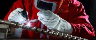
Welding bronze or brass with an argon apparatus is performed in one layer. And at the same time, you need to cook not with a whole seam, but in small separate sections (rollers).
Welding brass structures
Welding brass at home is a rather complicated procedure, since brass contains zinc, which evaporates when heated, as a result of which the product loses its original strength.
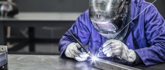
Brass itself is an alloy with zinc. The technology for joining parts made of brass is considered difficult due to the evaporation of zinc at high temperatures; this chemical element instantly oxidizes, resulting in the formation of a toxic, refractory oxide. Therefore, welding of brass samples should be carried out in specially equipped places equipped with an exhaust hood; welders should work in respirators.
Basic requirements for welding brass
- Cleanliness of the process when using argon-arc welding. Before starting work, the products are thoroughly cleaned to a characteristic metallic shine on the surface.
- There should be no oxides on the surface of the parts being welded; if present, they must be removed. Nitric acid is used for this. After this cleaning is completed, the product is washed in hot water and then dried.
When welding parts with argon, a characteristic continuous crackling sound is felt, and the welding arc has an amazing color. This is all due to the presence of zinc in the alloy. Brass does not burn through during the joining process, nor does it fly off in separate pieces, as it melts. Experienced welders advise welding brass in separate sections and not melting it in a continuous layer. When the material melts completely, there is a possibility of burning through the metal.
If it is necessary to weld a crater, then it is recommended to gradually reduce the welding voltage, increase the length of the arc and subsequently move it away from the workpiece. In the process of such a connection, the seam is filled in full; roasting of the zinc leads to its evaporation, resulting in the formation of defects in the metal. To reduce the evaporation of this chemical element, it is necessary to increase the presence of oxygen in the flame and use filler materials alloyed with boron, aluminum, and silicon.
Advice! When connecting brass parts, carry out welding work outdoors, do not neglect safety requirements!
Source: electrod.biz
At home
At home, the easiest way is to use an existing or borrowed blowtorch and tin solder.
And as a flux, that is, a material that separates the welding zone from atmospheric air, you can use cheap and accessible sodium borate. Sometimes special solders from copper and silver are prepared for soldering brass. If you are going to weld brass at home using the electric arc method, you need to think about protective equipment and strict precautions. Zinc vapor poses a truly serious danger to human health - it is poisonous.
Therefore, when welding brass, it is imperative to wear a protective mask, gloves and a respirator. For the same reason, it is better to perform this process outdoors or in rooms with sufficiently powerful hoods.
Less experienced craftsmen will benefit from additional advice. First, it is advisable to practice on an unnecessary piece of brass of suitable sizes. Only after getting good at it and setting the correct settings for the device can you get down to real work.
Those who want to quickly join two metal objects should know what cold welding is. Although this name is not entirely correct. Relatively speaking, hitting two metal plates with a sledgehammer, as a result of which you can get a single product (and this is exactly what they did in ancient times), can also be considered cold welding.
But these days, this is what they call the connection of two metal parts thanks to special compounds, as well as these compounds themselves. They can be purchased at almost any specialty store and allow you to connect, repair and seal brass and bronze products.
The method of application is extremely simple: you need to stir the cold welding composition until you get a homogeneous mass. Then you should apply this mixture to both surfaces that need to be connected and press them tightly against each other for a few seconds .
In fact, cold welding is the glue for metals, and sometimes such glue can actually solve related problems at home. On the other hand, there are situations when real welding is indispensable.
Copper Gas Welding Technology
Gas welding of copper at home is the most common technology used in domestic conditions. The resulting weld using this technique is highly durable. It is thanks to this parameter that gas welding is in great demand among home craftsmen. To connect copper products at home, you need to have on hand:
- Welding machine
- Gas-burners
- Gas cylinders (acetylene)
- Copper wire
- asbestos
Some advice from experienced welders
- If the thickness of the copper product is no more than 1 cm, the connection can be made with one torch.
- If the thickness of the copper sample is more than 1 cm, it is necessary to use two burners at once, the second will serve for heating.
- To reduce the outflow of thermal energy in this case, additional asbestos sheets will be needed.
- When welding copper products, it is recommended to use electrical wire made of copper, previously cleaned of paint and varnish insulating coatings.
- Cleaning must also be carried out on the welded edges of the products. This condition should not be neglected, since the possibility of cuprous oxide formation depends on it.
All necessary conditions for preliminary preparation for welding work have been completed. This means you can proceed directly to connecting the prepared copper products.
Recommendations
- You should try not to overheat the heated sections of the connection that are located close to each other.
- The concentrated flame must be directed perpendicular to the seam directly to the edge of the wire.
- The wire should melt before the edges of the product. The cooking process continues until the entire seam is completely formed.
- It must be remembered that stopping an unfinished connection can lead to overheating of some areas of the product, resulting in cuprous oxide and the formation of cracks.
- The completed weld must be forged.
- For small thicknesses of products, the wire must be kept cold.
- If the thickness of the product is more than 0.5 cm, then the wire must be heated to a temperature of 200 degrees. Higher temperatures are also allowed, but not more than 500 degrees, since the grain of the metal will form, which will subsequently become quite brittle.
- The welded, forged seam must be brought to a temperature of 500 degrees and cooled instantly.
At this point, the connection of copper parts can be considered complete.