Heavy industry is currently gaining more and more momentum, because the production of parts, from a simple nut to the components of a spacecraft, requires the use of new technologies for the manufacture of woodworking and metal-cutting equipment itself. And, of course, in this case, not the last place belongs to the lathe. To hold the part at high spindle speeds, lathe chucks are used, the varieties of which depend on the purpose of the surface being processed, the shape of the workpiece and the type of cutting.
Choosing a lathe chuck
Lathe chucks are intended for installation on special and universal lathes. The design of such a chuck ensures the transmission of greater clamping force with much less torque on the clamping keys compared to spiral chucks. All domestic and foreign manufacturers produce chucks for lathes based on a hardened steel body; they include a set of hardened jaws.
In order to select a lathe chuck for the machine, you need to know the following data:
- Chuck outer diameter
. - Number of jaws in the chuck
(2,3,4,6); - Execution
(with solid cams, with prefabricated ones); - Type of fit
(with a cylindrical centering belt and fastening through an intermediate flange, with fastening directly to the flanged ends of spindles under a rotary washer in accordance with GOST 12593-93, with fastening directly to the flanged ends of spindles in accordance with GOST 12595-93, with fastening to the flanged ends of spindles of the Camlock type according to GOST 26651); - Bore hole diameter
; - Diameter of mounting holes
; - Number of mounting holes
.
When purchasing lathe chucks, you should also pay attention to the jaws; they may have different methods for securing workpieces. Remember that the cams are self-centering and have independent movement. More modern and expensive models of lathe chucks are equipped with a built-in pneumatic drive, which is capable of reliably fixing workpieces. Such “consumables” are very often installed on machines for processing large-diameter pipe parts.
In addition to such specific characteristics, you need to know the height of the lathe chuck, the type of stroke of the rod and jaw, and the height from the edge to the main jaw. It will not be amiss if you indicate to the seller the total clamping force in the jaws and the maximum possible rotation speed. You can find this information in the technical data sheet of the machine you are using. Sometimes the marking of the required lathe chuck is also indicated there.
Lathe jaw chuck: characteristics, diagram, classification
Of course, the issue of choosing a component should be taken very seriously, since it determines the effectiveness of the procedure and the quality of the resulting parts.
General concepts about lathe chucks
Lathe chucks are selected depending on the technical characteristics of the device and the spindle, in particular. They represent the main components of the equipment. The mechanism is a cam effect. Dimensions are selected depending on the parameters of the unique workpiece.
The cams ensure reliable fixation of the mechanism. Due to the action of mechanical force, which determines the tightness of the fastening, installation and fastening occurs. The workpiece is fixed using a chuck.
It should be taken into account that the parts that need to be processed have different sizes and diameters. A low-quality cartridge will not hold as tightly as possible; as a result of strong mechanical movement, it can fly off, and the workpiece with it.
The chuck ensures smooth movement of the fastener, while the workpiece will not move relative to the center.
In the simplest sense of the word, a chuck is a mechanism that is responsible for rotating the workpiece, making its processing efficient and smooth.
Purpose
Inside the type of part in question is a cam mechanism. This important component allows you to center and clamp the workpiece.
This happens due to the narrowing of the cam parts, and then clamping them with a quill. Only after the part has been completely secured can you begin working on a wood or metal lathe. If the procedure is not followed, the workpiece may not only fall out or be damaged, but also cause harm to the master.
You should carefully check the quality of fastening of the part in the chuck. First, specialists turn on the lathe at low power and see if the mechanism rotates well. If after a few laps everything is in order, they will continue to work at higher powers.
Classification of lathe chucks
There are several types of classifications: according to the number of cams, type of clamp, fixation mechanism, type of execution, accuracy class.
By the number of jaws in the chuck
Cams are responsible for the quality of fastening of parts. They are made of high quality metal.
Double cam
Options secure asymmetrical parts that are not processed. But they are also used for standardized workpieces.
Three-jaw
Optimal for producing hexagonal and round variations. Shunting occurs on three sides of the cams.
Four-jaw
The 4 jaw chuck consists of four units that function independently. Used for processing rectangular and square options.
The chuck jaws are divided into direct and reverse. Virtually no effect on performance. Selected depending on the type of cartridge input.
Direct
The clamping occurs externally. The cams are located on top and grab the part.
Reverse
Clamping occurs from the inside, from the inside. The object being processed is chosen to be hollow, so that it can catch on.
According to the workpiece fixation mechanism
The fixation mechanism is an important characteristic that determines the quality of work.
Wedge
Fastening occurs using three cams on a straight platform. Wedge variations are used for digitally controlled equipment.
Collet
There are no standard clamps. Their role is played by bushings with pliers (up to six pieces). Can be used on standard mechanical machines.
Lever
The part is processed by moving the mechanism with a lever. Quite a costly and lengthy process. Used to work with special, complex textured parts.
Drilling
The parts are secured by the pressure of the wrench. The principle of operation is similar to the operation of a drill, only in the opposite direction.
Thermal cartridges
An extraordinary look, which is practically not used in machines made in Russia. For fastening, the hole is heated, and for removal, too.
Hydraulic chucks
The mechanism is the same as the previous one, but not temperature is used, but the hydrosphere. The liquid medium additionally dampens vibrations.
Leashes
The part is clamped with a special leash. Convenient only for processing small surfaces.
Self-clamping
Such options are practical. The design includes clamps that are tightly fixed to the workpiece independently.
By type of execution
In the Russian Federation, the types of cartridges by design are regulated by GOST 2675 - 80.
Whole
Made from a piece of steel with parameters starting from 500 MPa. The most common type.
Made
A rail is made of steel, and a cam is attached to it. The latter is made of metal.
Overhead
Composite variations consist of non-ferrous metal, stainless steel, ferrous metals. Used for working with large-scale projects.
Cartridge accuracy classes
The accuracy of the device is determined in GOST 1654 86. There are four stages in total.
Class H
Normal indicators, averaged.
Class P
Higher class, used for making hard production parts.
Class B
High accuracy - used for processing small variations.
Class A
Particularly high accuracy. Scope of application: small and hard workpieces.
According to the material of manufacture
Cast iron variations are cheap and do not have decent quality. Steel is more expensive and has a service life 3-5 times longer.
Cast iron
The brand used is from SCH 30. Minimum speed. Professionals prefer not to use such variations due to their low efficiency.
Steel
The design is made of material with a rating of 500 MPa. Maximum speed and functionality.
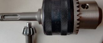
Chuck design: diagram and description
A lathe chuck consists of more than ten parts. Efficiency and service life are determined by the quality of the assembly and the material used to manufacture the set of parts.
Key
The main mechanism responsible for moving the workpiece on a lathe. It helps to secure the object being processed.
Spring
Attached to the key. Responsible for the turns of the latter.
Sleeve
Connected to a spring. Necessary to ensure free movement of the key through the mechanism.
Stopper
Connected with bushing and key. It is the main mechanism that is responsible for safety. The stopper controls the fixation of the workpiece and prevents it from falling off.
Gear
The disk, with the help of which the rotational movement occurs, is driven by a gear.
Flange
It is the base of the lathe chuck. Connects mechanisms to each other.
Spiral disc
Connects to gear. Responsible for receiving rotation. Regulates the degree and speed of processing.
Reverse cam
The mechanism is responsible for fastening the workpiece from the inside.
Cam straight
Direct variation is necessary to secure the object from the outside.
Classification of lathe chucks
Machine tooling with lathe chucks is represented by two-, four- and three-jaw chucks with manual and mechanized clamping. For various shaped castings, two-jaw self-centering chucks are used. Round and hexagonal workpieces are usually secured in three-jaw chucks. Four-jaw chucks are intended for rectangular and asymmetrical parts, as well as square bars. Let's take a closer look at the main types of chucks for lathes.
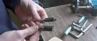
Collet chucks
The main working element of the collet chuck is a sleeve with several axial slots that divide it into petals, which, depending on the diameter of the workpiece, can be three, four or six. Such petals play the role of cams that compress the part that is inserted inside the sleeve. Collets are available as feeding and clamping. The feed collet is a hardened steel sleeve with three partial cuts that form petals with their ends pressed together. Solid clamping collets are made in the form of a bushing with spring-type petals.
Adhesion increases due to the narrowing of the slots during the procedure of pressing the collet into the cartridge with the conical part. From a technical point of view, the design of a lathe chuck with a collet has some advantages over other clamping devices - for a part that is fixed in a collet, the radial runout of the product is so insignificant that they can easily be ignored.
The primary area of use for such chucks is clamping cylinders, short bars or bushings for processing. They are also used for fixing cutters, drills, wrench tips and taps. Collet chucks are popular for secondary clamping of surface-machined workpieces. If the profile of the workpiece does not match the shape of the collet hole, it is customary to use replaceable inserts.
Lever chucks
Lever chucks can be used in small-scale production because their changeover procedure is simple and can accommodate workpieces in a wide range of diameters. On the centering surface in the cartridge body there is a disk, on the side of which there is a thread along an Archimedean spiral, a conical gear rim is cut on the other side.
The workpiece is secured in a lever lathe chuck by a hydraulic drive, which moves the rod with the coupling. The rods with crackers, which form a double-armed lever, are capable of rotating around the center of the cylindrical section of the cracker, moving the sliders with cams to the center and clamping the workpiece. Changing the lever chuck is simple and comes down to simultaneously moving all the jaws to the required radial position using a key.
This operation takes no more time than the procedure for securing the workpiece in a three-jaw chuck, which has a non-mechanized drive. Due to the moving elements that are provided in the drawings of lathe chucks and connect the slides to the main cams, errors in the centering of the workpiece are significant, so lever chucks are used mainly in roughing operations.
Four jaw chucks
This type of chuck has jaws that move independently of each other, which gives it a wide range of possibilities. On the other hand, due to the need to center the workpiece, securing the part requires more time than with self-centering devices.
The simplest four-jaw lathe clamps are a cast iron faceplate on which the jaws are clamped with screws. The faceplate has radial grooves on which additional equipment can be placed.
For large machines, massive chucks with T-slots are used. The cams are moved by screws, the axis of which lies on the plane of the faceplate. These chucks often use compound jaws.
Wedge cartridges
Wedge chucks demonstrate higher accuracy of workpiece centering than lever chucks. The workpiece is secured using a pneumatic or hydraulic drive, which is located at the rear end of the flat spindle. The three main cams and the cams that are associated with them, during the axial movement of the wedge, move in the radial direction and clamp the product.
For CNC machines where a large batch of parts is processed, it is important to be able to quickly assemble the lathe chuck and change the chuck to a different diameter of the workpiece being fixed, which lasts no more than 2 minutes. For machines with GPS and CNC, chuck designs are being developed with automatic readjustment to a certain diameter of the workpiece. The use of high-quality heat-treated steel for the manufacture of main parts increases the reliability, durability and accuracy of the chuck.
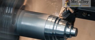
Milling and types of milling metal-cutting tools
The milling process includes cutting parts with a flat and shaped surface, performed on special milling machines.
A cutter is a cutting tool that rotates around a longitudinal axis, with a cylindrical, conical or shaped surface on which teeth with cutting edges that have increased hardness and wear resistance are placed.
Taking into account the increased force loads that arise during the milling process, it is customary to use materials with increased hardness and wear resistance for the production of cutters. Most milling tools are made from high-speed steels, and carbide, ceramic and diamond inserts are used to make teeth.
Milling tools operate under conditions of increased power loads, therefore, in their production the following are most preferred:
- high-speed steels;
- hard alloys (superhard materials);
- diamonds;
- metal ceramics.
To process parts that differ in shape, configuration of the machined surface, and materials, several types of cutters are used, differing in shape and technical parameters:
- conical;
- round;
- end;
- worm-type
There are also differences in the design of the milling tool. Milling cutters can be manufactured:
- solid - homogeneous material is used;
- prefabricated - the body (bearing part) of the cutter and teeth in such a tool are made of different materials and are connected to each other using fasteners;
- soldered - have soldered cutting elements
- welded - the teeth are welded to the cutter body.
The given configuration of the surface to be processed (planes, grooves, grooves, protrusions, etc.) determines the use of cutters with the appropriate parameters of the cutting surfaces, which affect the speed and quality of processing.
A wide selection of milling tools of various configurations, among which the most preferable is the use of face, end, disk, cut-off, keyway, groove, backed milling cutters, ensures milling even in hard-to-reach places of body parts.
Face milling cutters
It is customary to process flat surfaces. The cutting process is carried out by the cutting edges of the teeth located in the end part of the cutter. The geometry of the teeth varies according to various parameters, becoming more complex in accordance with the quality parameters of the material and topography of the parts being processed. To work on CNC machines, long-edge cutters are often used, which can provide the necessary precision.
End mills have a high degree of versatility
– they are used for cutting both metal and non-metal (wood, plastic) products in furniture and construction production. This tool can be used to cut contour grooves and grooves in parts made of steels and non-ferrous metals of medium hardness (not higher than 1 thousand N/mm2).
Cut-off cutters
perform work on cutting, cutting grooves and splines, or in combinations of these works. The cutting cutter has a flat cylindrical shape with teeth located around the perimeter of the circle, ensuring cutting of high-strength, medium-strength steels and cast iron. This tool is successfully used on universal milling equipment and CNC machines.
Key cutters
Designed for cutting grooves for dowels. These cutters have a tapered shank and are used when working with brass and annealed cast iron.
When milling shoulders and grooves in parts made of metals and alloys, three-sided disk cutters are used,
equipped with insert knives onto which carbide plates are soldered. Three-sided disk cutters are also used to process cast iron products using automatic and universal equipment.
Milling machines
Depending on the location of the spindle axis, milling machines are divided into:
- vertical – for processing metal and plastic parts;
- horizontal – for processing stamps, spirals, frames.
In addition to milling operations, such machines are used for:
- countersinking;
- boring;
- drilling holes.
| Vertical milling machine: 1 – cutter, 2 – spindle, 3 – trunk, 4 – bed, 5 – table, 6 – slide, 7 – console, 8 – base plate | Horizontal milling machine: 1 – foundation plate, 2 – bed, 3 – console, 4 – slide, 5 – table, 6 – trunk, 7 – mandrel with cutter |
When processing complex and hard-to-reach surfaces, as well as when it is necessary to obtain high precision and cleanliness of processing, multi-axis machines with numerical control are used, on which it is possible to perform sequential milling processes in automatic mode. CNC milling machines are successfully used in many industries where high-precision processing of parts made of metals and alloys is necessary.
Programming the processing of parts on CNC milling machines greatly facilitates the work of machine operators, while at the same time providing the possibility of step-by-step processing without reinstalling parts, which increases the accuracy and cleanliness of machined surfaces.
The use of cutters with teeth of increased hardness of various configurations makes it possible to process parts made of almost any metals and alloys at high cutting speeds, including preparing cutting parameters in accordance with the specified cleanliness and accuracy, conducting processing, monitoring during operation, and checking the final results.
Diaphragm cartridges
The highest accuracy of centering of parts is ensured by the diaphragm cartridge. Elastic membranes are attached to the cartridge flange with bolts. Such a membrane has from 3 to 8 cams with replaceable jaws. Some designs of diaphragm cartridges have cams that are bolted to the diaphragm. The workpieces are installed all the way into the unclenched jaws with their butts on the pins, the pneumatic drive is turned off, the membrane tries to return to its original state and clamps the workpiece with the jaws.
The large number of jaws on the diaphragm lathe chuck helps center the workpiece with an accuracy of 0.05 millimeters or better. Due to the low workpiece holding force, such chucks are used in finishing operations with a small cross-section of the chips being removed. When installing workpieces into a diaphragm cartridge, the pneumatic drive is used exclusively to open the jaws, so operations with such a cartridge are safe. In the event of a sudden decrease in pressure in the network during processing, the workpiece is still securely held in the chuck by the elastic forces of the membrane.
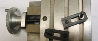
Securing chucks on a lathe
Fastening and centering of lathe chucks is carried out on the spindle of the lathe. The diameters of the cartridges and methods of their fastening are standardized. Depending on the manufacturer, the cartridges will be designated by type (according to ISO) or version (according to GOST). A common spindle end design is a Type C or Type D (cam-lock) mount. There are other spindle designs.
For fastening lathe chucks, flanges and faceplates placed on the spindle are widely used. They have the same design as a lathe chuck flange, but these attachments offer significant versatility since they can accommodate a variety of chucks. The faceplates have numerous holes for tightening bolts and a centering lug. When mounting the chuck on a faceplate or flange, high accuracy can also be achieved.
Three jaw chucks
Chucks that have three radial grooves have such a characteristic feature - centering, which occurs simultaneously with the workpiece being secured. The jaws move in a spiral synchronously under the action of a force that is applied at one point using a socket lever or key, depending on the transmission mechanism used in the design of the chuck.
The design of a three-jaw lathe chuck uses different types of jaws. Straight ones are installed in the groove outward in steps, and the part is clamped from above by the internal surfaces or the outer surface of the steps along the inner surface of the product. Reverse jaws are arranged in steps toward the center and are used for clamping workpieces with large diameters. The jaws are marked with a serial number, which must be followed when installed in the chuck.