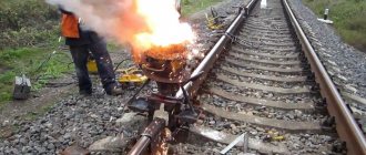
Gas welding is one of the types and methods of joining metals and their alloys under high temperature. Today we’ll talk about the basics, its technology, methods and techniques, advantages and disadvantages. This article will be useful for novice gas welders who want to master this difficult profession, as well as experienced craftsmen who want to strengthen their knowledge in this area.
Features of gas welding
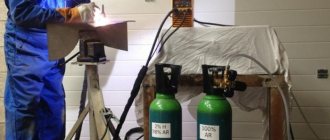
Gases that are easily flammable when reacting with oxygen are suitable for welding metal structures. These are propane, methane, hydrogen, gasoline vapors. The work is done manually. Welding equipment operates without electricity. Oxygen is supplied from a specialized cylinder, which, in accordance with GOST, is painted blue.
Provided there is a uniform supply of oxygen, carried out under low pressure, the combustion process takes place continuously. This factor is controlled by the gearbox included in the equipment. Hoses extending from the burner provide oxygen and acetylene. The main processes take place in the chamber. Here the ingredients are mixed and come out through the tip in the form of a flame.
Gases used and their characteristics
Most often, a specific gas, acetylene (C2H2), is used for flame welding. It is characterized by a pungent odor and is produced by the reaction of calcium carbide with water (in an industrial setting). At temperatures above 335 degrees it lights up. In combination with oxygen, the ignition temperature is lower - 297 degrees minimum.
The main gas for gas press welding is oxygen, which is mixed with C2H2 in equal proportions. It is always sold in blue cylinders. Using a hose, oxygen is connected to the burner and supplied at low pressure, no more than 4 atm. C2H2 is connected to the hole nearby. the torch has a special mechanism for mixing gases and the concentrate for the welding process comes out through the tip.
Gas welding and cutting of metals can be carried out not only with acetylene. Instead, it is permissible to use other gases in liquid and vapor form. The most popular acetylene substitutes:
- Kerosene vapors (acetylene replacement ratio – 1:1)
- Propane (acetylene replacement ratio – 1:0.6)
- Methane (acetylene replacement ratio – 1:1.6)
- Hydrogen (acetylene replacement ratio – 1:5.2)
Important: when flame welding steel products with methane or propane, you need to use wire with a high concentration of manganese and silicon.
For high-quality melting of metal, it is recommended that the exposure temperature be twice as high as the melting temperature of this metal.
Technological process of gas welding
Before butt welding, it is necessary to carry out preparatory work. These include cleaning the seam edges, choosing torches, methods and technologies of the welding process. There are two main techniques, the essence of which lies in the nature of the movement of the equipment.
Left way
Welding from right to left is the most popular method of joining metal structures. Applicable to thin-walled structures and low-melting metals. A wire is advanced in front of the flame, which is directed towards the unconnected edges of the parts. The tip of the wire is located in the recovery area. The welder can easily observe the soldering process. The metal warms up better.
Right way
Welding from left to right. Used to work with metal products with a thickness of more than 3 mm. In this case, the additive is carried out behind the flame located towards the connected area. This ensures a reduction in gas and filler material consumption. The seam lies flat.
When welding metal sheets less than 8 mm thick, oscillatory movements of the nozzle are performed. If the metal is thicker than the specified value, there is no need to perform such actions. An angle of 30° to 40° is formed between the mouthpiece and the surface being treated. The edges of thick metal sheets are cut at a smaller angle. The tip of the wire is kept in the weld pool. The liquid metal is mixed in a spiral, which ensures trouble-free removal of defects.
Among other technologies, semi-automatic operation stands out. It is produced using protective gases and an electric arc.
Features of pipe welding
Gas welding is quite widely used in the installation of small-diameter pipes (up to 100 ... 150 mm), in the manufacture of elbows, tees, bends and other structural elements of pipelines. Pipes are welded with butt welds with an acceptable seam convexity (1 ... 3 mm) depending on the wall thickness.
In the case of welding pipes with a wall thickness s ≤ 3 mm, the edges are not beveled. The joint is assembled with a gap of up to 0.5s. When welding pipes with s > 3 mm, bevel the edges at an angle of 35 ... 45°. The sharp part of the edges is dulled so that they do not melt during welding and the molten metal does not leak into the pipe. In some cases, depending on the purpose of the pipelines, other, more complex methods of joining pipes are used: without bevel of the edges with a backing ring; with socket and insert ring; with cutting edges and internal recesses in pipes for more accurate centering, etc. When welding these pipelines, it is prohibited to use the remaining backing rings.
To connect pipes, both left and right welding methods are used. Before welding, the pipes are aligned so that their axes coincide, then they are grabbed in several places around the circumference and welding begins. To center pipes during welding, various devices are used, one of which is shown in Fig. 3.
If the pipe can be rotated, then welding is best done in the lower position (Fig. 4).
The fixed joint is welded sequentially with bottom, vertical and ceiling seams. This case is the most difficult for welders, as it requires the ability to make seams with different positions in space.
In non-rotating joints of pipes with a diameter of up to 150 mm (Fig. 5), first the lower half (section 1) is welded, then the upper half (section 2) is welded in the opposite direction. The beginning and end of the upper seam are welded with overlap in zones A and B. When welding pipes with a diameter of up to 300 mm or more (Fig. 6), welding begins with
Rice. 3. Clamp centralizer for pipes with a diameter of 60 ... 100 mm
Rice. 4. Sequence of welding pipe joints with rotation : a - placement of tacks (1 - 3) and weld sections (A - D); b - execution of the first layer in sections AB and GV; c - turning the joint and making the first layer of the seam in the HA and VB sections; d, e - execution of the second and third layers of the seam, respectively, at any point on the circle and is performed in four sections (1 - 4).
When welding industrial and domestic gas pipelines with gas pressure up to 1.2 MPa, the pipes are pre-welded under production conditions in sections, the length of which is selected based on the possibility of transportation. Pipe sections are cleaned and primed with anti-corrosion insulation, after which preparatory work is carried out. The welding wire must have a certificate.
Rice. 5. Sequence of welding a fixed joint of pipes with a diameter of up to 150 mm
Rice. 6. Sequence of welding large diameter pipes : a - with a diameter of 200 ... 300 mm; b - with a diameter of 500 ... 600 mm; c - without turning the pipes
In the absence of a certificate, six special samples are welded for subsequent testing according to a specific method (three samples each for tensile and bend angle tests).
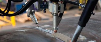
After completing the preparatory work, the surface of the edges and the adjacent outer and inner surfaces of the pipes are cleaned to a metallic shine to a width of at least 10 mm around the circumference. Assembly and welding of the ends of pipes with a longitudinal seam should be carried out with a displacement of the longitudinal seams by 50 mm around the circumference in relation to the seam of the previous pipe.
The surface of the deposited metal along the entire circumference should be slightly convex, with a smooth transition to the base metal, without undercuts or unwelded areas. The height of the convexity of the seam is allowed to be 1 ... 3 mm, but not more than 40% of the pipe wall thickness. The width of the seam should not exceed the thickness of the pipe wall by more than 2.5 times. Sagging and rough scaliness are not allowed. Joints that do not satisfy the listed requirements in appearance are rejected or subject to correction. Correction of joints by repeated suture is not allowed.
Rice. 7. Sequence of welding pipe joints with a canopy : a, b - first and second stages
If it is not possible to get close to the object with a torch (for example, when welding pipes for hot or cold water located in rooms near walls), gas welding with a visor is used (Fig. 7). Preparing a joint for welding requires certain professional skills.
Determination of gas welding modes
Gas welding modes are selected for the specific grade of metal being joined in accordance with the characteristics of the alloy and the diameter of the additive. Their difference lies in the thermal power, which is calculated by multiplying the thickness of the alloy being welded (S), expressed in millimeters, and the proportionality coefficient (k), which depends on the type of steel. This gives the formula:
Va = k*S,
where Va is the thermal power expressed in acetylene consumption.
Most often, for welding using the right-hand method, the initial thermal power is taken as acetylene consumption in the amount of 120 - 150 l/h. If you choose the left welding method, this indicator is in the range from 100 to 130 l/h per 1 ml.
The angle of the mouthpiece is expressed in the values presented using the table:
Tilt angle80°70°60°50°40°30°20°
| Metal thickness, mm | From 15 | 10-15 | 7-10 | 5-7 | 3-5 | 1-3 | Up to 1 |
When selecting filler material, take into account the selected method of welding and the thickness of the metal. Most often, its diameter is equal to half the thickness of the metal being welded. So with a material thickness exceeding 15 mm. an additive with a diameter of 6–8 mm is selected.
To determine the welding speed, the formula is used:
V = A/S,
where V is the welding speed;
A – coefficient inherent in a material with certain properties;
S is the thickness of the metal being welded, expressed in millimeters.
Preparing parts before welding
Before welding, the edges of the product being welded and the area 20...30 mm wide on the side adjacent to them must be cleaned of scale, rust and other contaminants. Scale, paint and other contaminants are removed mechanically or by chemical etching. The latter method is used mainly for cleaning non-ferrous metals and alloys.
The presence of contaminants on the surface of the base metal can lead to the formation of lack of fusion, gas and slag inclusions in the weld.
Rice. 7. Butt joint with a V-shaped one-sided bevel of the edges with different thicknesses of the parts : s, s1 - thickness of the parts; l is the length of the bevel of the edge of a part of greater thickness; c is the amount of edge dulling
When butt welding parts of different thicknesses, a part with a larger thickness s1 is processed until the thickness s of a thinner part is obtained (Fig. 7). This ensures their simultaneous melting during welding.
Before welding, it is advisable to assemble the parts in special devices and tack them with short seams to ensure their correct relative position during the welding process. Tack welding is performed under the same conditions as the main welding. The length of the tacks and the distance between them depend on the properties and thickness of the metal being welded, as well as on the length of the seam. When welding small components made of thin metal, the length of the tacks is no more than 5 mm, and the distance between them is 50 ... 100 mm. When welding metal of considerable thickness and a long weld, the length of individual tacks can reach 20 ... 30 mm, and the distance between them can be 300 ... 500 mm. The height (thickness) of the seam at the tack location should be 0.5 ... 0.7 of the thickness of the base metal. It is necessary to ensure complete penetration of the metal in the places where the tacks are applied, since during welding they may not melt to the full thickness.
Rice. 8. The order of applying tacks in a longitudinal seam : a - from the center; b - from the edge; 1 - 7 - sequence of tack application
The order in which tacks are applied depends on the thickness of the base metal and the length of the weld. To avoid warping, long-length connections are usually tacked according to a certain pattern (Fig. 8).
Other popular gas welding methods
- Welding using baths.
The principle of operation is directly reflected in the name of the method - as the work progresses, more and more new weld pools are formed. When one of them occurs, the end of the filler rod is lowered into it. It liquefies there, and then plunges into the reducing portion of the flame. At this time, the nozzle is moved further along the seam - to where the next bath will be formed. Each of them is carried out as if overlapping, overlapping the previous one by about a third of the diameter of the filler material.
This gas welding method is widely used for fillet brazing of pipes made of low-alloy steel or low-carbon alloys, as well as when working with thin metal plates.
- Welding using a through bead.
The welding operation is as follows: first, the metal structural elements are installed in a vertical plane so that between them there is a gap equal in width to half the thickness of the sheet. Then the nozzle moves evenly along the groove, melting the upper edge of the workpiece hole. At the same time, a layer of molten metal is applied to the lower part of the furrow. In this case, a scar is formed in the form of a roller, which connects the structural elements. The seam is dense, without slags and pores.
- Multilayer gas welding method.
When performing work in this way, during surfacing of the upper layers, the lower layers are annealed. Thanks to this, each level is thoroughly forged before the next one is formed. It is important to clean the bottom layer before applying the top layer. The operation is performed in short areas. The result is a durable, high quality seam. It is worth noting that this method requires large volumes of welding gas, it is not very productive and is quite expensive. Therefore, this connection option is used to perform very important work.
- Oxidizing flame and deoxidation welding.
Scope of gas welding
The use of gas welding allows you to solve such production problems as:
- soldering (including repair work);
- surfacing;
- cutting rolled metal and metal pipes into individual parts;
- welding of elements into one structure.
Gas welding machines are often used in industrial production and garage workshops, construction and auto repair shops, as well as in public utilities. With the help of such a unit, various elements of complex structures, thin-walled pipes are connected, and joints of products made of non-ferrous metals are made.
Soldering and cutting, performed using gas welding, allow you to achieve the desired result with the proper quality.
Soldering is carried out due to three key factors: strong heating of the edges of the elements being connected occurs, the solder melts, and a special antioxidant substance - flux - is added to these two components. Due to the mutual penetration of solder molecules and the material of the structural parts (diffusion), a strong, neat seam is formed at the joint. If necessary, it can be subjected to further processing.
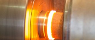
Surfacing is the coating of a base material with a layer of metal with other characteristics. To do this, the soldering surface is preheated to the “fogging” temperature. Using this method of gas welding, worn surfaces are often repaired, parts are lengthened or expanded, and the wear resistance and strength of elements are improved. Thanks to this, you can reduce the cost of repairs, reduce the consumption of rare or expensive materials, and extend the service life of the product.
Areas of use of welding
Welding of this type differs from electric arc welding in the gradual heating of the metal. Perhaps this determined the areas of its use. Gas welding shows maximum effect when working with steel up to five millimeters thick. This welding technology is successfully used in the processing of non-ferrous metals. Gas welding is used to work with materials that require preheating. When choosing gas welding, the designer must be guided by the requirements of GOST.
Gas welding is used for repair work and soldering. It is used to restore worn parts, such as crankshafts. To do this, a layer of metal is fused onto the worn surface. Subsequently, the overlay area will be polished and brought to the required size.
Left and right welding methods: selection criteria
The thickness of the workpieces is not the only criterion for selecting a manual gas welding method. The choice is also influenced by the spatial position of the elements. If they are in the lower position, then they are selected based on the thickness of the metal as described earlier.
If the intended seam is in a vertical plane, the left-hand method is used, that is, the torch moves from right to left following the filler rod. When working with scars in the horizontal plane, the left method is also chosen. In this case, the flame is directed towards the forming seam. To avoid leakage of liquefied material from the weld pool, it is performed with a slight distortion.
If the site of the intended scar is on the ceiling, use the right gas welding method. In this case, the flame flow is directed towards the formed seam, which prevents material from flowing out of the weld pool.
The effectiveness of a particular method depends on the conditions under which it is applied. It is generally accepted that the right method is characterized by greater productivity and energy efficiency, but this is only true in cases where the thickness of the workpiece exceeds 5 mm, and the material itself has high thermal conductivity. For thinner metals, the left method is optimal.
Technique of suturing in various spatial positions
Down position
Welding in the lower position is the simplest; in this case it is easiest to control the process of seam formation. The likelihood of lack of penetration and the appearance of other defects is reduced. The technique used is, as a rule, spiral-shaped movements of the end of the autogen mouthpiece. The additive is lowered into the heated weld pool, a “loop” is made and the operation is repeated. Each subsequent turn should overlap the previous one by 1/3 of the diameter.
Thin sheets are butt welded by flanging the edges, i.e. the edges of the workpieces are bent and welded without the use of filler wire. You can use both right and left connection methods.
Lap seams
Work should be carried out, if possible, without interruptions. If you pause, before repeating the process, melt the metal that has crystallized in the crater. Welding is carried out using the left-hand method with filler material. When working with this type of connection, it is more advisable to use arc technologies, as they are less expensive and more productive. This will especially affect large volumes.
Vertical position
Possible options for making vertical seams both from top to bottom and from bottom to top. In the first case, the right method is used (used when the metal thickness is small), in the second method, both options are possible. A certain amount of skill is required to hold the weld pool and prevent it from flowing down. It is ensured by the correct position of the mouthpiece, as well as the pressure of the gas flame.
If the parts are significantly thick (up to 20 mm), filling the seam with metal should be done with a double roller. In this case, edge preparation is not required; the gap between the parts should be half the thickness of the workpieces being welded.
Ceiling position
Requires accuracy and maximum concentration. Before feeding the wire, the edges are heated. When they begin to melt, wire is introduced into the weld pool zones. The end of the filler melts quickly, forming a weld. The metal is held in the weld pool by flame pressure. Cook in the right way in several stages, making each layer small in thickness. To prevent the metal from flowing down the rod, it should be kept closer to the horizontal plane of the ceiling seam.
Advantages and disadvantages
We figured out what gas welding is; it is a welding method using gas to heat a metal surface. As a result, the base softens and forms a weld pool. The combustion process of the gas mixture is ensured by the introduction of pure oxygen into it.
Gas welding technology has a number of advantages:
- This welding method does not require the use of special equipment, namely a welding inverter or a semi-automatic machine.
- All consumables can be purchased at any store with welding equipment; they are not very expensive.
- Gas welding can be carried out even without the use of a powerful energy source.
- The technological process is quite simple; even welders who do not have much experience can perform it.
- It is possible to control the welding process modes.
- The use of personal protective equipment is not always necessary.
- By using high-quality filler wire and the right flame, high-quality and durable welds can be obtained. For this reason, it is often used when connecting component pipelines.
- The work product warms up quite slowly, which is what allows it to avoid deformation or failure, as when using semi-automatic welding and electrodes.
In addition to the positive qualities, gas welding technology has negative features:
- During the process, the metal heats up for a long time, this negatively affects productivity;
- the heat area that is generated by a gas burner is large;
- It is quite difficult to retain the heat created by a gas burner. Compared to electric arc technology, it is more diffuse;
- welding using gas mixtures is considered an expensive method of joining metals;
- When joining thick metal parts, the melting rate of the seams is significantly reduced. This is due to the low concentration of heat that comes from the gas burner;
- gas welding technology is difficult to automate. The process of welding thin-walled pipes and tanks, which is performed using a multi-flame torch, can be mechanized;
In no case should you carry out overlap welding, as this can lead to deformation of the seams.
Wire and flux for welding
To weld metals, in addition to gas, you also need wire and flux. It is due to these materials that the welding seam is created and all its characteristics are formed. The wire used for welding must be clean, without signs of corrosion and paint on its surface. In some cases, a strip of the same metal that is being welded can be used as such wire. In order to protect the weld pool from external factors, it is necessary to use a special flux. Boric acid and borax are often used as such flux, which are applied directly to the surface of the metal being welded or to the wire used for welding. Gas welding of carbon steel can be performed without flux, and when joining parts made of aluminum, copper, magnesium and their alloys, such protection is necessary.
Advantages and disadvantages of gas welding
The features of gas welding are such that some of its properties can be regarded, depending on operating conditions, as advantages or disadvantages. The following table will help you determine the absolute pros and cons of this technique for fastening metal structures:
Advantages and disadvantages
| Simple process | Low efficiency |
| Availability of units and gas mixtures | High cost of acetylene |
| Work without connection to powerful energy sources | Large heating area |
| Possibility to select the type and power of flame | The ability to weld exclusively manually (the work process is automated if a multi-flame torch is used and structures with thin walls are welded) |
| Providing control over modes |
The boundaries of the melted zone during gas welding are large. Their heating rate is low. When welding tool steel, cast iron and non-ferrous metals, this feature is positioned as an advantage. After all, they need to be gradually heated and cooled. In other cases, the slow heating rate turns into a disadvantage.
Gas welding with high power flame
With this method of gas welding, the torch is used with a power twice as high as with the conventional welding method, and a flame is set with an excess of acetylene by 7-10%. The edges of the metal are heated only until melting begins. Gas welding of steel is carried out as follows. The edges are heated by a carburizing flame, as a result of which their top layer is enriched with carbon and the melting point of the metal decreases. At a temperature of 1200°C, the edges begin to melt (sweat). At this time, a filler wire heated to melting is introduced into the weld. The molten metal of the wire dissolves the carburized top layer of the base metal and is firmly bonded to it. Deep melting of the edges cannot be done, as this will result in a high-carbon, brittle layer.
The wire diameter is larger than in conventional welding. Edge bevel 60-70°C. Gas welding is performed in the right way. This method provides greater welding speed, but requires a highly qualified welder.
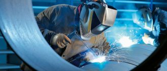
Safety precautions for gas welding
Welding work is particularly dangerous. The use of the gas welding method is no exception. It is worth noting that it requires increased precautions, since welding gases: oxygen and acetylene pose an additional threat. Compliance with safety standards will protect the technician from work-related injuries.
The generator and the gas cylinder must be at least 5 m apart from each other. To avoid damage to the connecting hoses, they must be suspended. If other specialists are also working in the room for gas welding operations, then protective items should be placed around its perimeter.
Before igniting the burner, the hoses are purged: first, the oxygen supply is opened, and then the acetylene supply. Only after this can the flammable mixture be ignited. It is worth making sure that the channels are always clean, otherwise popping or kickback may occur.
Do not operate the welding machine with oily hands or allow the equipment to come into other contact with oil, as this may result in an explosion. If a kickback does occur, it is necessary to promptly shut off the gas supply valves on the cutter, cylinders and water seal. Flames spread slowly through the hoses, but detonation may occur if the specified measures are not taken immediately.
To avoid kickback when working with one of the gas welding methods, it is important to exclude the following factors:
- drop in oxygen pressure - this can occur due to the end of the gas in the cylinder, clogging of the injector or freezing of the reducer;
- the distance from the nozzle to the part is too close - this reduces the gas flow speed;
- excessive heating of the welding tip or pipes;
- clogging of the mouthpiece - this provokes a reduction in the passage opening and, as a result, a drop in the gas flow rate.
If the torch overheats, it is necessary to pause welding work and cool it, for example, in water. An acetylene generator should not be emptied until the gas runs out. Otherwise it may cause backlash.
When performing work using any gas welding method, gas leaks must not be allowed. The most vulnerable places: taps and plugs. You can identify the hole using a soap solution.
Welding operations should not be carried out on containers or pipes that are under pressure. Before working with containers for acids or flammable materials, they must be thoroughly cleaned, rinsed with water and steamed. During manipulations, the lids must be open.
During short breaks in work, it is necessary to close the valves on the burner, and during long breaks, also on the cylinders. In summer, containers with welding gas should not be exposed to direct sunlight.
Recommendations
When studying the essence of the gas welding process, it is necessary to understand that working with flammable gases requires increased caution and attention. It is recommended for a beginner to take into account the advice of experienced welders and apply them in practice:
- for study and training it is better to use oxygen and acetylene;
- for welding with propane it is better to use a GZU 3-02 torch and Sv08g2s wire;
- before cooking the product, it must be thoroughly cleaned;
- for gas pressure welding, it is better to use hydraulic equipment (press) for reliable bonding;
- The left and right methods have their advantages and disadvantages, so the choice is made by the master, depending on the situation.
We reviewed the basic concepts and materials for flame and gas press welding. For them, a standard mixture of oxygen and acetylene is predominantly used. In some cases, propane welding is used for replacement. This process is not easy and has many nuances that will be difficult for a beginner to take into account. In this regard, novice welders are not recommended to weld with propane. The quality of the seam and the ease of work are affected by preliminary preparation.
Gas welding modes
The selection of gas welding mode depends on many factors.
First you need to choose the right gas burner. It mixes oxygen and acetylene in the required proportions. With its help, the flame level is adjusted by adjusting the supply of combustible gases.
There are burners without injector and with an injector. In practice, injection ones are most often used. In such burners, combustible gas is supplied under low pressure into a mixing chamber, where it is injected with a stream of oxygen.
Welding flame power
Burners differ depending on the flame power:
- G1 – micro-low power;
- G2 – low power with acetylene flow rates of 25-700 l/h and oxygen flow rates of 35-900 l/h;
- G3 - medium power, assuming the supply of acetylene 50-2500 l/h, and oxygen 65-3000 l/h;
- G4 – increased power.
The power of the welding flame is determined by the level of acetylene consumption. It is necessary to select the power based on the melting temperature of the metal being welded, its thickness, and thermal conductivity.
To calculate power, the formula is used: Q=A * h:
- acetylene consumption is designated – Q and is measured in m3/h;
- metal thickness is measured in millimeters and denoted h;
- the letter A denotes a coefficient describing the cost of acetylene per 1 mm of welded material. For steel the coefficient is 0.10 - 0.12, for cast iron - 0.15, for aluminum - 0.10.
Based on the ratio of oxygen and acetylene directed into the burner, three types of flame are distinguished: neutral, oxidizing and carburizing. Depending on the desired qualities of the deposited metal, the appropriate type of flame is selected. Most often, a neutral flame is used, which provides the highest mechanical characteristics of the deposited metal. Other types of flame are rarely used. For example, a carburizing flame is used for easily oxidized metals.
Welding speed
When gas welding, you must observe the speed of work.
To calculate the speed, the formula is used: V = A / S, where:
- V – operating speed, measured in meters per hour;
- S – metal thickness in millimeters;
- A is a special coefficient that takes different values depending on the type of metal and its thickness.
Filler wire diameter
Welding wire, various rods or metal granules can be used as filler material. The diameter of the filler material is calculated using the following formulas:
- d = S / 2+1 – with the left welding method;
- d = S / 2 – with the right welding method.
If the diameter of the metal being welded exceeds 15 mm, then the diameter of the filler material must be at least 6 mm.
There are some recommendations for welding different metals. For example, when gas welding steels, high quality work can be achieved by using manganese and silicon-manganese wires of the following grades: Sv-08GS, Sv-08GA, Sv-10G2.
For welding cast iron, rods of grades A and B are used. Grade A is used in hot welding when heating the entire product. Grade B is used in welding with local heating.
Gases for flame processing, their properties and storage conditions
For welding, flammable substances are used, the properties of which are given in table. 1, and the possibilities of their use when welding various materials are given in Table. 2.
The highest temperature is achieved by combustion of gases in an oxygen atmosphere - gaseous grades 1, 2, 3 according to GOST 5583-78 and liquid grades 1 and 2 according to GOST 6331-78.
Table 1. Properties of flammable gases, their substitutes, oxygen and their storage conditions
| Substance | Maximum flame temperature, °C | State of the substance in the container | Working pressure, MPa | Container color | Connection thread | |
| with air | with oxygen | |||||
| Acetylene | 2325 | 3150 | Dissolved | 2,5 | White | Attached with a clamp |
| Hydrogen | — | 2400…2600 | Compressed | 15 | Dark green | ∅ 21.8 mm, 14 threads per 1", left |
| Methane | 1875 | 2400…2500 *1 | Compressed | 15 | Red | » |
| Propane | 1925 | 2700…2800 *1 | Liquid | 1,6 | » | » |
| Butane | — | 2400…2500 | » | 1,6 | » | » |
| Kerosene | 1930 | 2400…2450 | » | 0,3 *2 | Ball | M12 |
| Petrol | 1970 | 2500…2600 | » | 0,3 *2 | » | M12 |
| Oxygen | — | — | Compressed | 15 | Blue | 3/4", right |
*1 When heating the mixture.
*2 In the tank.
Table 2. Possibility of using various flammable substances for gas welding of materials
| Materials to be welded | Acetylene | Hydrogen | Natural and city gas | Propane-butane mixtures | Kerosene, gasoline |
| Become: | |||||
| low carbon | + | + | ± | + | + |
| alloyed and highly alloyed | + | + | – | – | – |
| Cast iron | + | + | + | + | + |
| Aluminum and its alloys | + | ± | ± | + | + |
| Magnesium alloys | + | – | ± | + | + |
| Copper | + | – | – | – | – |
| Brass | + | + | + | + | + |
| Bronze | + | + | + | + | + |
| Nickel, nichrome | + | – | – | – | – |
| Lead | + | + | + | + | + |
| Zinc alloys | + | + | + | + | + |
| Silver | + | – | – | – | – |
| Glass | + | + | + | + | + |
Notes:
- “+”, “–”, “±” - the use of this flammable gas is expedient, impractical and limited accordingly.
- Illuminating kerosene is used for welding. When working on tractor kerosene, welding equipment becomes clogged with resinous substances.
Operating principles of welding equipment
Gas welding work requires strict adherence to safety regulations. The welder's station must be equipped with a special table, holding devices and a set of tools. All equipment must comply with the industry standard (OST). Before work, you need to blow out the valves and install the gearbox on the bolts. The screw for adjusting it and the locknut are turned counterclockwise all the way. Hoses are attached to the gearbox, which need to be blown out and connected to the burner and mouthpiece. Next, the operating pressure and burner ignition are set.
Compliance with the work plan will help to avoid backfire (burning gas at high speed in the direction opposite to the supply).
Nuances of welding various metals
The welding machine is equipped with a gearbox. With its help, the composition of the mixture used is controlled. The flame type is selected - oxidizing, reducing or highly concentrated (with a high concentration of combustible gas). When welding, a molten pool is formed. Redox processes take place in it. Oxidation is more active if aluminum and magnesium are used during operation. There are other nuances when welding parts made of specific metals:
- Low carbon steel. Various gases are suitable for welding. Steel wire with the addition of a small amount of carbon is used as an additive.
- Alloy steel. The choice of welding method depends on the composition of the alloy. Heat-resistant structures made of stainless materials are welded with an additive containing chromium and nickel. When welding some types of metals, molybdenum must be present in the wire.
- Cast iron. A carburizing flame is selected for welding. This prevents the decomposition of silicon and the formation of white cast iron grains with brittle properties.
- Copper. The flame is set to high power. A minimum gap is created between the parts. Additive – copper and flux.
- Brass. The burner flame creates a high concentration of oxygen. Select a brass additive. This prevents the formation of porous seams.
- Bronze. It is welded with a reducing flame using a bronze additive containing silicon. This technology allows you to preserve tin, silicon and aluminum in the alloy.
Compliance with established rules helps to create a high-quality seam. The metal is pre-prepared. After joining, thermal forging of the metal occurs. This allows you to increase the strength of the areas adjacent to the seam.
Sources
- https://svarkaspec.ru/svarka/vidy-svarki/gazovaya-svarka.html
- https://any-test.ru/answers/test/naks-obshii-ekzamen-uroven-2
- https://vt-metall.ru/articles/480-sposoby-gazovoj-svarki
- https://osvarka.com/vidy-i-sposoby-svarki/gazovaya-svarka
- https://weldering.com/sposoby-gazovoy-svarki-0
- https://elsvarkin.ru/texnologiya/gazovaya-svarka-rezhimy/
[collapse]
General information about carbon and low alloy steels
According to the chemical composition, steel is divided into carbon and alloy.
Based on their intended purpose, steel is divided into structural and tool steel. The largest volume of welding work involves the use of low-carbon and low-alloy structural steels. The mechanical properties of carbon structural steel are determined by carbon. Carbon steel is smelted of ordinary quality and high quality.
Carbon steel of ordinary quality is divided into three groups: group A - according to mechanical properties; group B - according to chemical composition; group B - according to mechanical properties and chemical composition. The following grades of steel are produced:
- group A - St0, St1, St2, St3, St4, St5, St6;
- group B - BSt0, BSt1, BSt2, BSt3, BSt4, BSt5, BSt6;
- group B - VSt0, VSt1, VSt2, VSt3, VSt4, VSt5.
According to the degree of deoxidation, ordinary quality steel has the following designation: kp - boiling; ps - semi-calm; sp - calm. Boiling steel containing no more than 0.07% silicon is obtained by incomplete deoxidation of the metal with manganese. This steel is characterized by a pronounced uneven distribution of harmful impurities (sulfur and phosphorus) throughout the thickness of the rolled product.
Calm steel is obtained by deoxidation with manganese, aluminum and silicon. It contains at least 0.12% silicon; sulfur and phosphorus are distributed more evenly in it than in boiling steel. This steel is less prone to aging and has good weldability.
Semi-quiet steel, in terms of its tendency to aging, occupies an intermediate place between boiling and calm steel. Semi-quiet steels with grade numbers 1 - 5 are smelted with normal and increased (up to approximately 1%) manganese content. In the latter case, the letter G is placed after the brand number (for example, BSt3Gps).
Group A steel is not used for the manufacture of welded structures. Group B steel is divided into two categories. For steel of the first category, the content of carbon, silicon, manganese is regulated and the maximum content of sulfur, phosphorus, nitrogen and arsenic is limited. For steel of the second category, the maximum content of chromium, nickel and copper is also limited.
Group B steel is divided into six categories. The full designation of steel includes grade, degree of deoxidation and category number. For example, VSt3Gps5 means: steel group B, grade St3G, semi-quiet, category 5. The composition of steel of group B is the same as the steel of the corresponding grades of group B, 2nd category. Steel grades VSt1, VSt2, VSt3 of all categories and degrees of deoxidation are produced with guaranteed weldability. Steel grades BSt1, BSt2, BSt3 are supplied with a guarantee of weldability at the customer’s request.
High-quality carbon steel is produced in accordance with GOST 1050 - 88. The steel has a low sulfur content. The permissible deviation for carbon is 0.03 ... 0.04%. Steel with a carbon content of up to 0.20% inclusive can be boiling (kp), semi-quiet (ps) and calm (sp); the rest became only calm. For subsequent mild steels, the letters “sp” are not placed after the numbers. For the manufacture of structures, high-quality carbon steel is used in the hot-rolled state and, to a lesser extent, after normalization and hardening and tempering. Carbon steel, in accordance with OST 14-1-142 - 84, is divided into three subclasses: low-carbon steel (with a carbon content of up to 0.25%); medium-carbon (with a carbon content of 0.25 ... 0.60%); high-carbon (with a carbon content of more than 0.60%).
Low carbon steel is mainly used in welded structures.
In welding production, the concept of weldability of various metals is very important. Weldability is the ability of a metal or a combination of metals to form, with the established welding technology, connections that meet the requirements determined by the design and operation of the product.
According to weldability, carbon steel is conventionally divided into four groups: I - well weldable; II - satisfactorily weldable (to obtain high-quality welded joints of parts made of this steel, strict adherence to welding conditions, special filler materials, certain temperature conditions, and in some cases, heating and heat treatment are necessary); III - limited weldability (to obtain high-quality welded joints, heating, preliminary or subsequent heat treatment is additionally required); IV - poorly weldable (weld seams are prone to cracking, the properties of welded joints are reduced; steel of this group is usually not used for the manufacture of welded structures).
Low carbon steel can be welded well using existing fusion welding processes. Ensuring the uniform strength of the welded joint does not cause difficulties. The seams have satisfactory resistance to the formation of crystallization cracks. This is due to the low carbon content. However, in steel containing carbon at the upper limit, the probability of cold cracks increases, especially with increasing cooling rate (increasing metal thickness, welding at subzero temperatures, welding with small-section seams, etc.). Under these conditions, the appearance of cracks is prevented by preheating to a temperature of 120 ... 200 ° C.