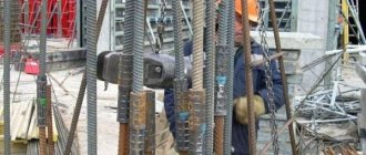
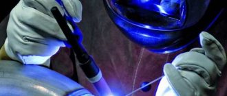
The installation of railway lines is carried out using two methods: prefabricated and welded. The second is preferable because prefabricated joints reduce the speed of rolling stock. Welding of rails is carried out using several methods. When choosing a method for installing seamless lines, the weldability of the material and the cost of the work are taken into account. The most common are resistance and aluminothermic welding, there are other types. Each one is worth mentioning separately. The joints are welded using special equipment.
General information
This type of ensuring the integrity of the canvas has been known and used for a very long time, enjoys stable popularity and is considered a classic solution, but work is still underway to improve it. Innovative solutions are periodically introduced to speed up welding and also reduce its cost without compromising the final result.
Why is there still no single technology that would be optimal? Because there are limitations that arise in the production of rails: they are specially made from high-strength metals so that they last longer. And the more reliable the VSP element, the less susceptible it is to controlled heating and plastic deformation.
If you increase the hardness of the rolled product beyond measure, it will be more difficult to connect it with the same structures laid in the track. Therefore, manufacturers of I-beams do not experiment, and responsible contractors, accustomed to making highways conscientiously, adhere to clearly established standards, in particular, GOST 103-76.
Thermite treatment
Aluminothermic technology has been tested by time. The use of thermite welding of rails is based on a reducing reaction that occurs when the base (aluminum) comes into contact with another component - iron oxide.
The resulting metal (reduced iron) at operating temperatures of about 2000 degrees is poured into a special fire-resistant form that matches the geometry of the rails being welded.
This reaction is accompanied by the release of a significant amount of thermal energy.
Welding rails using the thermite method began a very long time ago (from the mid-19th century), but since then this type of welding, due to the use of aluminum, began to be called aluminothermic.
It is important to note that the described chemical reaction after igniting a special high-temperature fuel (thermite) lasts only a few seconds.
In addition to the two components considered (iron and aluminum oxide), alloying additives and small steel particles are introduced into the working welded mixture, which slightly slow down or dampen the ongoing process. Additives are necessary to ensure that the steel in the welding zone acquires the required qualities and parameters characteristic of most rail products.
When considering the features of this type of welding process, it should be noted that upon completion of the reaction, the total chemical mass is divided into two fractions: liquid metal and light slag, which floats to the top of the mold.
Termitan technology allows the following types of track products to be connected to each other:
- surface-hardened rail blanks;
- volumetrically hardened joining parts of rails,
- rails that have not undergone special heat treatment in any combinations.
This type of welding ensures compliance with the requirements of the basic standards for high-speed rail lines, in terms of compliance with welding technology standards.
Weldability properties
The correct choice of electrodes allows you to solve the problem described above, that is, to ensure high quality joints with relatively little time and effort. Good options (from those that are constantly on sale and are relatively inexpensive) are SSSI from the 13/45 and 13/55 series, which are suitable even for critical facilities or reinforced structures.
Although it is even more important to choose the right method and, in the process of its implementation, adhere to the norms and requirements prescribed in the interstate standard 103-76. This will simplify work that is already being carried out with not the most favorable initial data.
Electric contact method
The electric contact approach to connecting rail joints is based on their strong heating and subsequent melting through an electric arc, which is formed by a significant low-voltage current.
To implement the method, special machine complexes are used that operate in automatic mode (MSGR-500, MS-5002 or K-190, for example).
Before welding, the rails to be processed are laid either directly on the tracks, or with a slight offset inside the branch or outside the track (at a distance of about 260 centimeters from its axis).
In this case, the welding mechanism itself moves along the restored thread, that is, it is a self-propelled rail welding station.
During its operation, replaceable contact heads of various types are used, providing the necessary welding modes (continuous reflow or intermittent heating of contacts).
Features of welding rail joints
We have already found out that profiles for rutting are made of particularly strong metal, namely high-carbon steel. This is a material that has its own specific heat treatment: exceeding the exposure temperature will result in internal stresses, the appearance of cracks and other minor defects that can cause an accident.
To ensure sufficient quality of the seam and at the same time minimize the likelihood of microdamage, when connecting two VSP elements, the following rules must be observed:
- Use professional equipment as the most accurate, productive and safe in its class.
- Take a responsible approach to purchasing consumables (we have already mentioned the importance of the same electrodes).
- Be sure to use fluxes (where they are needed) and other solder auxiliaries.
- Adhere to the optimal operating mode selected earlier (we will look at the features of each later).
- Pay attention to the post-processing of the seam, and then check it with appropriate instruments for integrity.
During the operation of the rut, welded strands must be periodically inspected for microdamage in order to promptly prevent more significant damage.
Arc welding
In electric arc welding, rails are joined by the metal of an electrode, which is melted by the heat of the arc discharge. Electric arc welding of joints does not require the application of sediment pressure. For this welding, alternating current from a transformer or direct current from a mobile welding unit is used. The best method of electric arc welding is the bath method, in which the ends of the rails, cut perpendicular to the longitudinal axis, are installed without a fracture in plan, and in the profile with an elevation of 3-5 mm, and in this position they are fixed with a gap of 14-16 mm. An electrode is inserted between the ends, through which a current of 300-350 A is passed. The molten metal of the electrode fills the gap between the ends along the entire cross-section of the rail. To prevent the molten metal of the electrode from spreading, inventory copper molds are used to close the gap from the bottom and sides. The set of molds consists of three bottom and two side plates, installed first when welding the base (Fig. 152, a), then when welding the neck and head of the rail. The quality of welding is noticeably improved by using a lower curved plate (Fig. 152, b), which ensures heating of the rail base. The welded joints are carefully ground along the entire perimeter of the rail. The quality of a joint welded by the electric arc method depends on the quality of the electrodes and their coating, the constancy of the liquid state of the metal until the end of the welding process, and the thoroughness of the seam processing. Rice. 152. Installation diagram of copper molds for electric arc welding Electric arc welding is used only for rails laid on station tracks, except for the main and receiving and departure tracks.
Types of rails
The chemical alloy of the metal structure laid on the sleepers plays an important role. According to GOSTs, it must be strictly defined for each profile, and the following table will help you understand what is used.
| Name | Marking | Purpose |
| Railway | ||
| standard | RP50 (65, 75) | for highways (lines of primary importance) |
| narrow gauge | P8 (11, 18, 24) | for shafts and curtains of reduced width |
| industrial | RP50 (65, 75) | for short distances |
| Crane | KR70 (80, 100, 120, 140) | to ensure the movement of construction and bridge special equipment |
| Rudnichnye | P33 (38, 43) | for creating switches and continuous sections of mine conductors |
| Witty | OR43 (50, 65, 75) | for circular supports and switch crossings |
| Frame | PP65 | for installation of intersection lines |
| Counter rail | RP50 (65, 75) | for dead-end settling tanks |
| Trams | T58 (62) | for arranging the route of movement of the corresponding transport (not designed for any other) |
| Antennae | UR65 | for crosses with a continuous rolling surface |
Technologies and methods of rail welding
Quite a lot of methods have been invented, but the most widespread are those that have the following features:
- involve relatively low labor costs;
- take into account ductility, fluidity, compatibility of different brands of metal structures.
Let's look at the current options.
Electric arc
It is carried out using electrodes, and these can be:
- Russian SSSI 13/45 or 13/55;
- Japanese LB 52U.
but each of them should first be calcined and then held at 180-230 0C for 120 minutes.
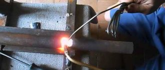
Suitable for both lashes and butt joints and even for damaged areas, it is implemented according to the following scheme:
- The edges of adjacent VSP elements are cleaned and ground to improve the final quality of the seam;
- the prepared I-beams are laid in their places (on sleepers), but with a specially provided small gap;
- an electrode is placed in the gap between the ends of the rolled products, which is subjected to a discharge, as a result of which it melts, fills the free space and thus firmly connects the two metal structures.
Electric arc welding of rails is non-contact, which is quite convenient, does not require the application of excess sedimentary pressure, the current for its implementation can be either constant or alternating and come from a mobile station. It turns out that this method can be used even when the line being laid lies at some distance from the main line and/or the centralized power supply system.
Let's summarize the key advantages:
- high-quality results are achieved without the use of additional (and significant) efforts;
- the ends do not have to be pre-cut - it is enough to prepare them;
- accessibility to implementation - to obtain an arc, you can connect to any inverter, rectifier or transformer.
These advantages explain why it is so widespread.
“Bathtub” method of welding rails
A special case of electric arc, so named because when it is implemented, the ends of adjacent VSP elements are placed in a special tank, which holds the melt.
This process has other features:
- all installation operations are carried out at some elevation;
- the gap between metal structures is 14-16 mm;
- the diameter of the electrode is 5-6 mm, and it should be inserted vertically;
- AC or DC current with a power of 300-350 A is supplied, but of strictly straight polarity.
As a result of this, the joint is uniformly filled with melt, and a diffusion layer is formed over the entire cross-sectional area.
With this approach, rail welding has the following advantages:
- there is no need to use flux, and the coating already prevents oxidation;
- the ends do not need to be pre-cut, which saves time;
- connection density is achieved without the application of additional forces;
- You can connect to any current sources - this is always an option available for implementation.
To prevent metal from leaking beyond the boundaries of the tank, special fences are installed. Upon completion of the operations, all that remains is to ensure the quality of the seam and sand it - this will help prevent microcracks, and therefore maximize the service life of the canvas.
Manual arc welding
Another special case: its implementation scheme is similar to the previous ones, even a bath can be used, it’s just that all types of work are performed by people, not machines. Naturally, a person loses to a machine in productivity: he cleans the ends more slowly and does not place them as accurately.
So why is this method still popular? Because it is convenient when you do not need to lay many kilometers of path, but you just need to lay a couple of I-beams or repair damage right on the spot. It is perfect for situations in which local replacement or repair is relevant, when it is simply irrational to bring equipment and connect it.
Thermite method
It is based on a reduction reaction: to start it, you need to mix aluminum powder, metal oxide (usually iron) and other components, set it on fire and quickly heat it to 1200-2000 0C. After which all that remains is to pour this melt into the bath with the ends of the lashes pre-cleaned and laid at the desired angle. Attention, this needs to be done in just a few seconds. The oxide will fill the mold and, when hardened, form a strong seam and push out the slag, which can be cleaned off without any problems.
The working composition also contains alloying and damping (braking) additives - for strength and resistance to mechanical damage - and ignition particles. The latter are very important, since they ignite already at 800 0C (while all the others - at 1200 0C) and help maintain uniform melting throughout the entire reaction, which takes place in just a few seconds.
Due to the fact that the mixture contains the most powder, this method is often called aluminothermic, and it can also be used to connect the following track products:
- volumetrically and surface-hardened;
- various metal structures that have not undergone heat treatment, but are already being put into operation.
The seams made ultimately meet all GOST requirements, even for critical and high-speed fabrics.
Gas press welding of rails
Here, the joints of adjacent VSP elements are connected at a temperature significantly lower than the melting limit, but under high pressure.
The method requires preliminary preparation, namely the combination of two metal structures and vertical cutting of the ends using a circular saw. This allows the contact surfaces to be sanded clean later, while ensuring the tightest possible seal. Then they should be processed and preserved (protected from oxidation), for which carbon tetrachloride or dichloroethane is suitable. After which you can proceed to the main operations, that is:
- press the I-beams against each other with a powerful hydraulic press (with a force of up to 10-13 tons);
- use multi-flame burners to heat the area along the contact line until the temperature in this area reaches 1200 0C;
- make sure that shrinkage does not exceed 20 mm;
- normalize the seam, that is, clean and polish it;
- After cooling, perform a quality check.
This technology has three important advantages:
- the chemical composition in the working area is homogeneous;
- you can connect VSP elements of different thicknesses and even configurations;
- there is no scale, since all processes take place exclusively in the thickness of the rolled products.
Electric contact welding of rails
It is based on the principle of strong heating of the joints and their further melting by an arc generated by current at low voltage.
Attention, the technology is fully automated (which is convenient), and it is implemented by specialized machine complexes, for example, self-propelled K-190, MS-5002 or MSGR-500. The scheme for its implementation is simple:
- metal profiles are laid either on the track itself, or with a slight internal/external offset (not exceeding 260 cm from the center, that is, from the axis);
- equipment - a mobile station - moves in the direction of the web and carries out heating of contact points at a programmed frequency or continuous melting.
In this case, the system selects the most suitable types of replaceable contact heads for a particular case.
The advantages of the method are clear: there are no errors that could be caused by human factors, the accuracy of combining VSP elements is maximum, the force of influence in similar cases is the same. Plus, overall labor safety is better, and the equipment operates at a given speed, without breaks for lunch or smoke breaks, its productivity is definitely higher.
On the other hand, the use of such complexes requires significant financial costs. Therefore, in cases where you just need to add a couple of new I-beams or repair cracks in those requiring repair, the good old technology of welding rail joints using a manual arc method is more rational. Automated self-propelled guns should be driven to places where entire kilometers of metal structures need to be laid; when solving large-scale issues, they pay for themselves many times over, which cannot be said about local tasks.
Basic methods
Welding of rail joints belongs to the category of particularly important activities, the organization and implementation of which is impossible without the use of equipment and modern welding mechanisms.
The main types of welding technologies used in the installation and repair of rails are:
- electric contact welding;
- electric arc method;
- thermite treatment (aluminothermic welding of rails);
- modern gas-press welding.
Each of these methods has certain advantages and disadvantages. To become more fully acquainted with them, we will consider each of the listed welding methods in more detail.
Quality control
The safety of trains, locomotives, and wagons directly depends on how strong the connection is in the end. Therefore, any seam made either by machine or by man must be checked - using any non-destructive method, naturally, after the metal has cooled. It is imperative to evaluate the cleanliness, smoothness, and evenness of its surface. You should also make sure that the head of the VSP elements complies with all GOST standards, that the vehicle wheel can rest on it correctly, without the possibility of derailment.
Application of butt welding in industry
The use of resistance butt welding in practice accounts for about 10% of the total application of resistance welding. Basically, flash butt welding is used.
Resistance butt welding is used for welding wire with diameters up to 8 mm from steel, aluminum, copper, rods with a diameter of up to 25 mm, pipes with a diameter of up to 50 mm. This welding method is also used in the production of chains, rims, wheels, etc.
Flash butt welding has found application in the production of rings (frames) with diameters of 4-5 m, and strips during continuous rolling. It is also used in the manufacture of shafts, doors, partitions, chains, pipelines, railway rails in stationary and field conditions, combined cutting tools (drills, cutters, milling cutters, etc.).
Security measures
It is necessary to weld rails with electrodes using personal protective equipment, using only serviceable tools and devices and only with reliable grounding. If you entrust this task to machines, you need to make sure that the automated complex is working properly and will function according to the given program. It is important to check even consumables: if any of them is defective or does not meet the required level of quality, it must be replaced.
Equipment for resistance butt welding
Resistance butt welding machines
Machines for resistance butt welding are quite diverse in design and are classified according to the same criteria that are accepted for the classification of machines for spot and seam resistance welding. For example, they are also divided according to the type of welding. These are resistance and flash welding machines. They are also divided according to the type of current, their purpose and other characteristics.
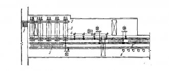
The figure shows a diagram of a universal machine for resistance butt welding. The main components of the machine are the frame 8, welding transformer 9, secondary circuit 10, movable 4 and fixed 11 plates, conductive jaws 3 for clamping parts, clamping cylinders 1 and 2, feed drive 5, guides 6 and control system unit 7. In practice, more often All AC machines are used.
In addition, specialized machines are used to weld parts of a certain range. For example, there are machines specifically for welding band saws, for welding chains, and for welding railway rails, which can be performed both directly on the tracks and in stationary conditions.
Resistance welding of pipes with a diameter of no more than 1 m is carried out on stationary and mobile installations in the field. To weld large diameter pipes exceeding 1.4 m, special welding complexes with machines that are inserted into the pipe are used.
In instrument making and radio electronics, capacitor machines are used that allow welding small parts with dimensions up to 1-2 mm. There are also DC machines, for example, for fusion welding of thin-walled titanium parts or for resistance welding of circuits.
Equipment control systems
Control system for supplying and turning off current, changing voltage and current, providing operations of clamping, heating, melting, upsetting, deburring, heat treatment in the machine, transporting parts, etc.
On simple machines of low power, control is carried out by limit switches. On more complex machines, control is carried out using cam devices, with the help of which the speed of movement of parts, heating time, the moment of application of the upsetting force and its magnitude are regulated.
On powerful machines, relay control is used. The magnitude of the secondary voltage is adjusted by switching the transformer stage or changing the switching angle of the thyristor contactor. The speed of movement of the plate is controlled by changing the speed of the electromechanical drive motor. The most advanced are adaptive control systems with feedback.
Devices and equipment
To install and secure parts, as well as supplying electric current to them, the design of the machines provides clamping current-carrying devices with various types of drives. Screw drives provide clamping force up to 40 kN, lever, eccentric and pneumatic up to 100 kN, hydraulic up to 50 MN. There are also electromechanical drives.
Welding electrodes are made of bronze or copper of the BrNBT, BrNK, MTs2, MTs3, etc. brands. To protect the welded parts from slipping, the shape of the electrodes corresponds to the edges of the parts. Using drives for moving or feeding the plate, the part moves slowly when heating and quickly when upsetting. Spring drives for moving electrodes create a force of up to 1 kN, lever drives up to 50 kN, electromechanical drives up to 75 kN and hydraulic drives up to 3 MN.
