02/07/2022 Author: VT-METALL
From this material you will learn
:
- Friction welding technology
- Main types of friction welding
- Welding modes
- Equipment for metal friction welding
- Advantages and disadvantages of friction welding
- Friction Welding Applications
If we talk about the features of the technology, friction welding is much simpler than electric arc or gas welding. In addition, this method boasts high productivity and minimal energy losses. That is why it is in great demand today in various areas of production.
Friction welding was invented in the Soviet Union in 1956. Since then, the technology has improved significantly, and now there are several varieties of this method of connecting parts, each of which is used in a specific situation. But let's talk about everything in more detail.
Content
- Concept and definition of friction welding
- Video: the essence of friction welding
- Advantages and disadvantages of friction welding
- Advantages
- Flaws
- Continuous Drive Friction Welding
- Inertia friction welding
- Combined type of friction welding
- Oscillatory friction welding
- Friction stir welding
- Orbital friction welding
- Radial friction welding
- Roller friction welding
- Surfacing using friction welding
- Weldability of various materials
- Requirements for the design of welded parts
- Preparing surfaces for friction welding
- Selectable welding modes with continuous drive
- Heat treatment of welded joint
Welding mode selection
Each of the described types of welding has several modes, differing in the speed of rotation of the moving parts, the compression force of the workpieces and the thickness of the welding ring (for radial welding). The physical parameters of the modes are determined by the technology of a particular production and all friction welding modes can be divided into three:
- low speed;
- standard;
- accelerated.
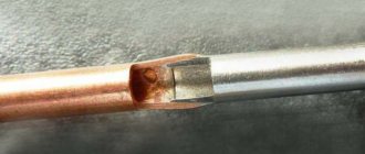
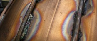
Friction welding at low speeds of rotation or friction of parts is used when the viscosity of the materials being welded is high (for example, copper workpieces), as well as when there is a risk of damage to the structure of the fibers of the part. High friction speeds are used when welding low-melting metals and alloys using the stirring method, and high pressure along the axis of rotation is used when welding parts without cavities (solid) using a continuous drive.
Concept and definition of friction welding
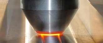
Friction welding is a technological process for manufacturing a welded joint, which occurs through the use of thermal energy arising on the contact surfaces of the workpieces being joined, pressed against each other with force, and at the same time, one of the workpieces moves relative to the other.
After an interruption or complete stop of the movement of the workpiece, friction welding is stopped by applying a forging force.
As with other pressure welding methods, the welded joint is obtained as a result of joint plastic deformation of the joined sections of the welded workpieces. But a distinctive feature of the friction welding process is the generation of thermal energy directly in the joint zone due to the transformation of work aimed at overcoming the friction forces between the workpieces. These forces arise from the mutual movement of the rubbing surfaces of the workpieces being welded.
Video: the essence of friction welding
Volume of a thin layer of heated metal
- When using a rotational motion, friction welding gives good results only if one of the parts is a rotating body (rod or pipe), its axis coincides with the axis of rotation, and the other part is a flat surface.
The ability to use friction welding is also limited by the cross-sectional size of the part being welded at this boundary. Calculations show that it is not practical to use this process for welding solid bars with a cross-section greater than 200 mm in diameter at the current level of technological development.
To weld such rods (with a cross-sectional area of 30,000 mm2 or more) you will need a machine with a power of about 500 kW, a speed of about 100–150 rpm and an axial force of more than 300 tf (294 MPa).
Advantages and disadvantages of friction welding
Advantages
1. High quality connection. At the joint there are no many defects inherent in welds obtained using other types of welding. For example, the formation of gas pores and weld cracks, various non-metallic inclusions and other defects is eliminated at the joint.
2. Constancy of mechanical properties. As a rule, the mechanical properties of the base metal, the joint and the area near it are practically the same due to the uniform structure of the metal.
3. High productivity of the method. The entire welding cycle takes from a few seconds to several minutes, depending on the size of the parts being welded.
4. Preparation for welding takes less time. Due to the fact that there is no need to remove oxide films from the surfaces being joined and clean them, this significantly saves preparation time.
5. No additional filler materials are required, as for many other types of welding.
6. No additional post-welding operations are required, such as tempering, annealing, forging, etc.
7. Costs for subsequent machining after welding are reduced.
8. There are no welding leads and a low degree of deformation after welding is completed.
9. Large range of materials to be welded. Friction welding allows you to weld many materials, both among themselves and in various combinations.
10. High metal utilization factor (CMM). Alternative methods for producing workpieces (castings, forgings, etc.) have a significantly lower CMM.
11. Less harmful. When friction welding, there is no bright blinding light, as with arc welding, there is no release of harmful gases, and there are no splashes of molten metal.
12. Easy automation. It can be achieved by installing welding machines in automatic and rotary production lines, or, for example, by using control computers operating according to programs.
13. Environmental friendliness of the process. Welding does not require protective gases, fluxes or coatings; therefore, there is no release of harmful substances into the air.
14. Low energy intensity. Compared to conventional arc welding, energy intensity is reduced by 10 times.
Flaws
1. Low versatility of the process and a relatively small range of welded parts.
2. The dimensions of the welded parts are limited. In the case of round parts, during welding of which one is fixedly fixed, and the second rotates around its axis (rotational welding), it is not economically feasible to weld workpieces with a diameter of more than 150 mm.
3. Expensive and bulky equipment for friction welding.
4. Distortion of fibers in the welding zone is possible if the welded joint is subjected to high dynamic loads during operation.
5. Lack of mobility. It is impossible to use this type of welding in “field conditions” and various installation works, since the welding equipment for friction welding is stationary and not mobile.
Introduction
Welding is one of the leading technological processes in industry, the degree of development and improvement of which largely determines the level of technology in mechanical engineering, construction and a number of other sectors of the national economy. Modern welding science and technology make it possible to reliably connect parts of any thickness and configuration - from parts of the smallest electronic devices to giant parts of machines and structures.
Welding has opened up the possibility of radically improving the production technology of all kinds of machines, instruments, and building structures. It promotes automation and mechanization of work in their production.
The current level of development of welding technology in our country is a solid basis for an even wider and more effective use of welding as a powerful means of significantly increasing labor productivity, saving metals in industry, construction, agriculture and transport, improving the quality and reducing the cost of products.
The further development of modern technology is largely determined by the development of new materials with special properties. This is due to the fact that nuclear energy, electronics, big chemistry, rocketry and other industries are characterized by extremely high process speeds, high pressures, high temperatures and some special effects. It is important that the structural material is stable under these operating conditions with rapid changes in temperature and stress, evaporates slightly in a vacuum without changing its properties when irradiated with nuclear decay products, resists the action of aggressive environments, etc.
The current state of technology is characterized by the increased use of rare metals and alloys and non-metallic materials. The development of them as structural materials and the expansion of their areas of application plays a vital role in technical progress.
In promising designs of new technology, such refractory and rare metals as tungsten, molybdenum, tantalum, niobium, zirconium, etc., which have high heat resistance, heat resistance, corrosion resistance and other specific properties, are widely used.
In a number of cases of operation under extreme temperature conditions, in extremely aggressive environments, in high-intensity neutron fluxes and under the influence of other special factors, even these metals cannot meet the requirements for products under their operating conditions. As a result, materials are created that have special properties. In addition, in some cases, increased demands are beginning to be placed on widely used materials due to their use in new types of critical structures.
In this regard, welders are faced with more and more new tasks of developing more advanced welding technology for widely used and new materials, which requires either the modernization of relevant equipment and technology, or the development of new, more advanced welding methods.
The use of rare and refractory metals in various branches of new technology as structural materials, which previously found limited use, mainly only as alloying additives, has raised the problem of developing methods for their welding. These metals constitute a group of difficult-to-weld metals due to the fact that, in addition to their high melting point, they are characterized by high chemical activity at elevated temperatures. Most of them react with all known fluxes, and some are getters. Therefore, in relation to these metals, such welding methods as manual arc welding with a consumable electrode, submerged arc welding and gas welding turned out to be unacceptable.
Cold welding of metals
To carry out cold welding, it is necessary to remove oxides and contaminants from the surfaces being welded and to bring the surfaces to be joined closer to the distance of the crystal lattice parameter; in practice, significant plastic deformations are created.
Cold welding can be used to produce butt, lap and tee joints. Before welding, the surfaces to be welded are cleaned of contamination by degreasing, treating with a rotating wire brush, or scraping. When welding butt wires, only the ends are cut off.
Sheets with a thickness of 0.2-15 mm are overlap welded by pressing punches into the thickness of the metal on one or both sides. Connections are made in the form of individual points or a continuous seam. The width or diameter of the punch is selected depending on the thickness δ of the material being welded: r=(1÷3)δ;
The main parameter that determines the cold welding process is the amount of metal deformation at the joint, which depends on the properties of the metal, its thickness, type of joint and surface preparation methods.
Cold welding can be carried out by squeezing the products being connected with their simultaneous tangential relative displacement. This welding method is called shear welding.
When a tangential force is applied, the surfaces begin to move, during which oxide films and contaminants are torn off and individual contact bridges are formed. The tangential displacement of the joined products makes it possible to obtain relatively large areas of surfaces cleared of films with a slight spreading of each of them. The presence of a tangential force reduces the resistance of the metal to plastic deformation and, at a given normal force, allows one to obtain a larger contact area. This leads to the fact that during shear spot welding, setting occurs with small deformations and forces.
When shear welding of dissimilar metals, a strong connection occurs only in metals with similar mechanical properties, for example, cold-worked aluminum and annealed copper and some others.
In cold shear welding, the main parameters are the amount of pressure and the amount of shear. The amount of pressure must be such that relative movement of the surfaces is possible. The magnitude of the shift does not depend on the size of the products and is determined by normal pressure and the geometry of the rubbing surfaces. A sufficient adhesion area of surfaces processed with a file occurs after a shift of 5-7 mm.
In shear welding, the shear strength of joints can be high if the overlap is sufficient, but the pull-out resistance is always low.
Types of friction welding, welding patterns
Continuous Drive Friction Welding
Continuously driven friction welding was the very first variation of friction welding.
To implement it, one of the workpieces is rigidly fixed, and the second workpiece is given a rotational movement, while both workpieces are bodies of rotation and are on the same axis (see diagram of friction welding with a continuous drive). Next, the workpieces are brought close together and some axial force is applied to the movable one. In continuous drive friction welding, mechanical energy is transferred directly to the joint where it is converted into thermal energy through dynamic contact between the two workpieces.
The heating stage in friction welding installations can be regulated by the heating time or the amount of mutual deformation of the workpieces. This is followed by stopping the moving workpiece and forging. Currently, in addition to continuous drive welding, quite a few types of friction welding have appeared, and now we will consider the most common of them.
Inertia friction welding
This type of friction welding differs from welding with a continuous drive in that mechanical energy is not transferred directly from the drive to the joint. This welding is based on the use of energy stored in the flywheel (see diagram of inertial friction welding).
The spindle, with the flywheel mounted on it, accelerates. After the flywheel has reached a certain moment of inertia of the rotating mass, the drive is turned off and the workpieces are compressed with a certain force. The welding process ends after the spindle stops.
The ranges of set welding parameters are as follows: speed 0.28-11.1 m/s. Compression pressure of workpieces: 47-465 MPa. The moment of inertia of the flywheel is chosen so that the angular acceleration is in the range of 150-300 rad/s2.
Combined type of friction welding
This type of welding can occur in two ways:
1) First, the workpiece rotates at a constant angular speed, and then the engine is turned off and the process is completed using the inertial method.
2) The start of welding occurs at a constant angular velocity and continues according to the inertial method. And at the moment when the spindle rotation speed reaches 5-6 rps, it instantly brakes.
Oscillatory friction welding
This type of welding occurs with angular vibration movements of one or both workpieces, or with reciprocating motion (vibration friction welding). In practice, this type of welding is used only for welding thermoplastics and thermosets together.
Friction stir welding
This is a relatively new type of friction welding, developed by the British Institute of Welding and introduced in the early 90s. The essence of such a process is shown in the figure below:
The tool, rotating at high speed, comes into contact with the welded edges at the joint and its tip is embedded into the workpiece to the full depth of the edges. In this case, the shoulder of the tool touches the joint surface. Next, the tool moves along the entire joint line. As a result of the friction of the tool tip on the workpiece, the welded edges are melted, mixed when the tool rotates, and are forced into the free area behind the moving tool.
The smooth surface of the weld is ensured by the tool shoulder, which touches the weld joint. At the end of welding, the tool leaves the joint area beyond its boundaries. We recommend watching a video that clearly shows the process of friction stir welding:
Orbital friction welding
A diagram of this process is shown in the figure.
The essence of this type of welding is that the welded workpieces pressed against each other move in orbits relative to each other. In this case, the workpieces do not rotate around their own axes. The axes of the workpieces are shifted by a certain amount e, called eccentricity. Due to this, their circular movements occur along a certain orbit, the radius of which is equal to the eccentricity radius e. When the workpieces have passed the heating stage, their axes are aligned and the circular movements stop. After this, forging is done and a welded joint is formed.
Orbital welding can be used to weld not only round workpieces. Since the workpieces do not rotate around their own axes, the shape of their ends can be any, but it is necessary to ensure uniform heat generation over the entire plane of the welded areas.
Due to the fact that the workpieces can be of any shape, this type of welding has become quite promising for joining products with a large cross-sectional area. However, not in all cases this type of welding is economically feasible due to complex equipment and insufficient reliability of clamping mechanisms. The low reliability of the clamps is due to the influence of large inertial forces on them. Because of these shortcomings, this welding method has not been widely adopted in industry.
Radial friction welding
The essence of this welding method is the use of heat generated by the friction of the outer or inner ring, which rotates at a certain angular speed, while coming into contact with the beveled ends of the pipes, pressed against one another with some force.
The diagram of radial friction welding is shown in the figure. While rotating, the ring heats up the ends of the pipes and at the end of the heating stage, then the rotation of the ring is stopped and it is further compressed in the radial direction.
Roller friction welding
This type of welding is used in cases where it is necessary to weld thin-sheet elements. The roller welding diagram is shown in the figure.
The essence of this method is that a roller rotating at a speed of approximately 1600 rad/s is brought to the edges of the workpieces. The roller moves relative to the edges being welded at a speed of 0.1-2.0 m/s, and the pressure created on the roller is in the range of 0.2-0.5 MPa.
Surfacing using friction welding
This surfacing is used in cases where it is necessary to restore worn surfaces of parts, or when it is necessary to ensure certain operational properties on the surfaces.
The friction surfacing scheme is shown in the figure. A rotating rod with an angular velocity of the order of 1600 rad/s is pressed against the surface on which surfacing must be performed, with a force F, and the surface itself moves with a linear speed Vzag. The thermal energy generated as a result of friction creates a thermal field that heats both the workpiece and the rod. In this case, the rod heats up much more due to the fact that the contact surface of the workpiece is constantly changing as it moves, but the contact surface of the rod remains unchanged. As a result, the rod melts and a layer of metal is transferred from the rod to the surface of the workpiece.
Features of the welding process
The capabilities of this technology allow friction welding of aluminum without the use of filler material and shielding gases. It provides complete penetration of metals within 3 cm thick without the risk of internal voids with pores. Good strength characteristics with minor deformations are achievable even in special cases of joining aluminum alloys, when other joining technologies do not guarantee success. This technology is also effective for welding alloys of lead, copper, magnesium and even titanium.
Radial technology has found application in friction welding processing of plastics and long products. For example, it is indispensable in the construction of pipelines when welding of pipes with fixed joints is required. In this case, it is necessary that both parts remain stationary. Therefore, they are heated by rotating a special insert into the gap between them, which is removed immediately before forging.
In the process of vibration or linear friction welding, one of the workpieces to be joined remains motionless, while the second performs transverse oscillatory movements. This method is effective for connecting products with a rectangular cross-section. One of its varieties is the vibration friction surfacing scheme. It involves the rod performing translational oscillatory movements in the direction perpendicular to the axis of movement of the workpiece being processed.
Friction stir welding is performed using a moving tool. During this process, the sheets or parts to be joined are held together in a motionless manner. The gap should be minimal. When a rotating tool is inserted into it and then moved along the weld line, the surface layer of the metal is heated. As the tool rotates, the ends of the workpieces melt, their metal mixes and forms a joint.
Friction welding technology
Localization of the thermal field and plastic deformation during the welding process ensures low energy consumption and allows welding of dissimilar metals, such as aluminum-copper, aluminum-steel, copper-cermets and others. In addition to saving energy, friction welding reduces the cost of subsequent processing of the welded joint.
Weldability of various materials
Data on the weldability of various metals and alloys to each other are given in the table below:
Requirements for the design of welded parts and equipment capabilities
When designing workpieces produced by friction welding, the following factors must be taken into account: the capabilities of the welding equipment, the ability to weld materials together, and securing the workpieces in the welding machine. The cost of preparing workpieces for welding and subsequent processing of the resulting joint, automatically obtaining the necessary alignment and angular position of workpieces, and creating, if necessary, a uniform temperature field and equal deformation conditions are also taken into account.
When assigning allowances for the length and diameter of workpieces, take into account the data given in the table.
In order to ensure the required alignment of the workpieces, it is necessary to securely fasten them in the clamping fixtures of the welding machine. In addition, an important indicator is the rigidity of the workpieces being welded along the length of their extension from the clamps. Recommendations for this length are shown in the figure:
If the overhang length is less than recommended, this may result in thermal release of the clamping fixtures.
Preparing surfaces for friction welding
When friction welding, the condition of the surfaces being welded has a much smaller impact on the quality of the welded joint than with other pressure welding methods. Surfaces for welding can be obtained by cutting with a guillotine, a circular saw, or even a gas cutter. Irregularities on surfaces will be eliminated by grinding in or additional heating time.
Deviation from parallelism of welded surfaces can reach 5-7° and this will not have a significant impact on the quality of welding. Small areas of corrosion, paint residues, oil and other contaminants on surfaces are removed during the heating stage. The exception is rust and scale obtained during rolling, forging or stamping.
When dissimilar materials are welded, more thorough surface preparation is necessary. For example, when welding aluminum to steel, the amount of end runout of the steel workpiece should not exceed 0.2 mm. The figure below shows some examples of preparing welded surfaces from dissimilar materials.
Selection of continuous drive friction welding modes
One of the main indicators is the rotation speed. As it increases, the weld becomes more uniform and the strength indicators increase. The rotation frequency is calculated based on the optimal speed V, m/s: for ferrous metals and alloys 2.6-3, for aluminum and copper about 2, for titanium 4-5.
Specific heating pressure. When welding carbon and low-alloy steels it is 30-60 MPa, for heat-resistant and tool steels 60-120 MPa, for welding aluminum and aluminum alloys 7-23 MPa, for welding copper with aluminum 40-60 MPa, aluminum with corrosion-resistant steel 6.4-12, 2 MPa, for welding titanium and titanium alloys no more than 18 MPa.
In practice, when welding homogeneous materials, the specific heating pressure can be varied within wide limits, obtaining a high quality welded joint. When welding dissimilar materials, the optimal heating pressure should be selected based on the deformation rate in a range that will ensure the same degree of deformation of both welded edges.
Specific lapping pressure. It is prescribed to improve the performance of welding equipment. Typically 15-20% of the specific heating pressure. For welding carbon steels it is approximately 10 MPa. The grinding time is 1-3s.
The specific forging pressure is selected based on the plastic properties of the materials being joined. Most often, the forging pressure is 100-300% of the specific heating pressure. When welding aluminum with corrosion-resistant steels, the forging pressure is selected within 800-1000% of the heating pressure. Forging time is usually 1.5-3s.
Heating time. This indicator greatly affects the cyclic strength and impact toughness of the welded joint, especially when welding dissimilar materials. The heating time is determined experimentally for each specific pair of workpieces. Increasing the heating time leads to grain growth.
Braking time. It should be as short as possible so that the flow of metal from the welded joint does not become stable. Intensive metal flow and sudden cooling prevent stress relief in the welded joint, and this reduces the strength and can lead to destruction of the joint immediately after the welding process is completed.
Heat treatment of welded joint
With the help of heat treatment, internal stresses in a welded joint are reduced, plastic properties are increased, recrystallization occurs and the quality of welding is improved as a result of diffusion processes.
Heat treatment is not carried out when welding low-alloy, high-alloy chromium-nickel austenitic and chromium ferritic steels welded in homogeneous and dissimilar combinations.
Medium-carbon alloyed and unalloyed steels, as well as high-alloy austenitic-martensitic, chromium ferritic-martensitic steels, welded in various combinations with each other, are subjected to heat treatment. Moreover, if the carbon equivalent of steels is above 0.8%, heat treatment is carried out from a heated state.
general information
Friction welding (or friction welding) is a method of joining homogeneous and dissimilar metals, the essence of which is to heat two parts by rubbing them against each other. The heat generated during friction melts the metal, forming a permanent connection. But friction is not the only thing used during welding. Here, the forging of parts after welding, as well as the pressure exerted on the workpieces, also plays a big role.
As you can see, the essence of friction welding is extremely simple, which is why such welding equipment is used in many modern industries. This method allows you to improve the quality and productivity of labor without hiring additional highly qualified employees. It is enough to train the welder how to properly configure the equipment; the rest of the processes take place automatically.
Friction Welding Equipment
The schematic diagram of the continuous drive friction welding machine is shown in the figure below:
The equipment for friction welding may include: a welding machine, a mini-computer with programs for mode parameters, a deburring machine, manipulators for loading and unloading, and transportation devices.
Equipment
The equipment may consist of different components, depending on the cost of the kit and the scope of application. The standard set consists of a welding machine, a deburring machine, and a manipulator (or robot) that can be used to move large parts.
To set up the equipment, you need to set the welding parameter, the spindle drive power, set the size of the workpiece that needs to be welded, and also set the welding speed.
An experienced welder will install most of the settings right away, but there may be problems with calculating the drive power. Therefore, we recommend using the following formula:
Where S is the area of the welded section in mm2, and Nsp is invariably 20 W/mm2.