What is a thyristor and their types
Many have seen thyristors in the “Running Fire” garland; this is the simplest example of the device described and how it works. A silicon rectifier or thyristor is very similar to a transistor. This is a multilayer semiconductor device, the main material of which is silicon, most often in a plastic housing. Due to the fact that its operating principle is very similar to a rectifying diode (AC rectifier devices or dinistors), the designation on the diagrams is often the same - this is considered an analogue of a rectifier.
Photo – Running fire garland diagram
There are:
- ABB turn-off thyristors (GTO),
- standard SEMIKRON,
- powerful avalanche type TL-171,
- optocouplers (say, TO 142-12.5-600 or MTOTO 80 module),
- symmetrical TS-106-10,
- low frequency MTTs,
- triac BTA 16-600B or VT for washing machines,
- frequency TBC,
- foreign TPS 08,
- TYN 208.
But at the same time, IGBT or IGCT type transistors are used for high-voltage devices (furnaces, machine tools, and other industrial automation).
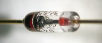
Photo – Thyristor
But, unlike a diode, which is a two-layer (PN) transistor (PNP, NPN), a thyristor consists of four layers (PNPN) and this semiconductor device contains three pn junctions. In this case, diode rectifiers become less efficient. This is well demonstrated by the thyristor control circuit, as well as any electricians’ reference book (for example, in the library you can read a book by the author Zamyatin for free).
A thyristor is a unidirectional AC converter, meaning it conducts current in one direction only, but unlike a diode, the device can be made to operate as an open circuit switch or as a DC rectifying diode. In other words, semiconductor thyristors can only operate in switching mode and cannot be used as amplification devices. The key on the thyristor is not capable of moving to the closed position on its own.
The silicon controlled rectifier is one of several power semiconductor devices, along with triacs, AC diodes, and unijunction transistors, that can switch from one mode to another very quickly. Such a thyristor is called high-speed. Of course, the class of the device plays a big role here.
Application of thyristor
The purpose of thyristors can be very different, for example, a homemade welding inverter using thyristors, a charger for a car (thyristor in the power supply) and even a generator are very popular. Due to the fact that the device itself can pass both low-frequency and high-frequency loads, it can also be used for a transformer for welding machines (their bridge uses exactly these parts). To control the operation of the part in this case, a voltage regulator on the thyristor is needed.
Photo - using Thyristor instead of LATR
Don't forget about the ignition thyristor for motorcycles.
Description of design and principle of operation
The thyristor consists of three parts: “Anode”, “Cathode” and “Input”, consisting of three pn junctions that can switch between “ON” and “OFF” positions at very high speed. But at the same time, it can also be switched from the “ON” position for different durations, i.e., over several half-cycles, in order to deliver a certain amount of energy to the load. The operation of a thyristor can be better explained by assuming that it will consist of two transistors connected to each other, like a pair of complementary regenerative switches.
The simplest microcircuits demonstrate two transistors, which are combined in such a way that the collector current, after the “Start” command, flows into the NPN transistor TR 2 channels directly into the PNP transistor TR 1. At this time, the current from TR 1 flows into the channels into the bases of TR 2. These two interconnected transistors are arranged such that the base-emitter receives current from the collector-emitter of the other transistor. This requires parallel placement.
Photo – Thyristor KU221IM
Despite all safety measures, the thyristor may involuntarily move from one position to another. This occurs due to a sharp jump in current, temperature changes and other various factors. Therefore, before you buy a thyristor KU202N, T122 25, T 160, T 10 10, you need to not only check it with a tester (ring), but also familiarize yourself with the operating parameters.
Typical thyristor current-voltage characteristics
To start discussing this complex topic, look at the diagram of the current-voltage characteristics of a thyristor:
Photo - characteristics of the thyristor current-voltage characteristic
- The segment between 0 and (Vо,IL) fully corresponds to direct locking of the device;
- In the Vvo section, the thyristor is in the “ON” position;
- The segment between the zones (Vvo, IL) and (Vн,In) is the transition position in the on state of the thyristor. It is in this area that the so-called dinistor effect occurs;
- In turn, points (Vн,In) show on the graph the direct opening of the device;
- Points 0 and Vbr are the section where the thyristor is turned off;
- This is followed by the segment Vbr - it indicates the reverse breakdown mode.
Naturally, modern high-frequency radio components in a circuit can affect the current-voltage characteristics in an insignificant way (coolers, resistors, relays). Also, symmetrical photothyristors, SMD zener diodes, optothyristors, triode, optocouplers, optoelectronic and other modules may have different current-voltage characteristics.
Photo - current-voltage characteristic of a thyristor
In addition, we draw your attention to the fact that in this case, device protection is carried out at the load input.
Thyristor check
Before you buy a device, you need to know how to test a thyristor with a multimeter. The measuring device can only be connected to a so-called tester. The diagram by which such a device can be assembled is presented below:
Photo – thyristor tester
According to the description, it is necessary to apply a positive voltage to the anode, and a negative voltage to the cathode. It is very important to use a value that matches the resolution of the thyristor. The drawing shows resistors with a nominal voltage of 9 to 12 volts, which means that the tester voltage is slightly higher than the thyristor. After you have assembled the device, you can begin to check the rectifier. You need to press the button that sends pulse signals to turn it on.
Testing the thyristor is very simple; a button briefly sends an opening signal (positive relative to the cathode) to the control electrode. After this, if the running lights on the thyristor come on, the device is considered inoperative, but powerful devices do not always react immediately after the load arrives.
Photo - tester circuit for thyristors
In addition to checking the device, it is also recommended to use special controllers or a control unit for thyristors and triacs OWEN BOOST or other brands; it works approximately the same as a power regulator on a thyristor. The main difference is a wider range of voltages.
Video: operating principle of a thyristor
Selecting a multimeter
To test various electrical equipment, a special measuring device called a multimeter is required. Main selection criteria:
- When choosing, attention is almost always paid to the degree of functionality of the device.
- Almost all devices can be divided into two main categories: pointer and digital. Today, arrows are practically not used, since they display a small amount of information and the accuracy of the data may be low.
- The error indicator can vary over a fairly wide range. High-quality models have an error of no more than 3%. It is better to choose a multimeter with the lowest error value, but they are expensive.
- The degree of comfort when using the structure. The measuring device can have a wide variety of sizes and shapes. If it is uncomfortable to use, serious problems may arise.
- Attention is also paid to the degree of protection from dust, moisture, and shock loads. A variety of materials can be used in the manufacture of a measuring device, some of which are characterized by high protection against moisture and dust.
- Electrical safety class. Based on this indicator, devices are classified according to established standards.
- Brand popularity. Good manufacturers of digital testers repeatedly check the reliability and quality of their products.
When considering how to test a Ku202n thyristor with a multimeter, it should be borne in mind that all such measuring instruments are divided into several classes:
- CAT 1 - devices suitable for working with low-voltage networks.
- CAT 11 - class of device suitable for power supply.
- CAT 111 is a class designed for work inside structures.
- CAT 1 V - for working with a circuit that is located outside the building. Devices of this class have high protection from environmental influences.
After selecting the measuring tool, you can begin testing. The received information can be recorded in a notepad or saved in the device’s memory if it has the appropriate function.
Specifications
Let's consider the technical parameters of the KU 202e series thyristor. This series presents domestic low-power devices, the main use of which is limited to household appliances: it is used to operate electric furnaces, heaters, etc.
The drawing below shows the pinout and main parts of the thyristor.
Photo – ku 202
- Set reverse on-state voltage (max) 100 V
- Closed voltage 100 V
- Pulse in open position – 30 A
- Repeated pulse in open position 10 A
- Average voltage =0.2 V
- Set current in open position
Photo – thyristor Ku202n
The price of a thyristor depends on its brand and characteristics. We recommend buying domestic devices - they are more durable and affordable. In spontaneous markets you can buy a high-quality, powerful converter for up to a hundred rubles.
Thyristor KU202N belongs to the group of triode devices with a p - n - p - n structure. The junctions are created by planar diffusion of silicon. The thyristor is designed to switch high voltages using small levels through an additional output. Depending on the switching circuit, it can open or close, providing the required operating modes of the device. It is used in blocking systems, protection systems, servo drives, remotely controlled switching systems, chargers as a switch or charge current regulator.
You can buy the KU 202N thyristor in many other places, because it is a fairly common component. Moreover, its price is much lower than imported analogues. It can also be found in many Soviet devices, from power supplies to switching devices.
Design
Structurally, the KU202N thyristor and the entire series are made in a metal case made of coated copper alloy, which has threaded terminals and two solder terminals of varying thickness and height. The size of the threaded outlet or anode (A) is M6 for the nut. The terminals are made rigid by filling with epoxy resin, but during installation, forces should not be used more than 0.98 N.
When soldering the power terminal (K), it is necessary to maintain a minimum distance to the glass of at least 7 mm, since high temperatures may damage its integrity. When connecting the control output (CE), you should maintain a distance to the glass of at least 3.5 mm for the same reason. In this case, the total holding time of the soldering iron is not recommended to exceed more than 3 s. The effective temperature of the soldering tool tip should not exceed +260 degrees.
Features of circuit connection
The thyristor is designed for voltage switching in various devices . But at the same time, there is a standard scheme for connecting it, which is highly recommended not to be violated. For example, a resistor must be connected between the cathode (solder pin) and the control electrode as a shunt component. Thanks to its presence, the control circuit is closed and the transition is saturated. Its resistance should be no more and no less than 51 Ohms.
If there is a voltage of negative polarity at the anode, then the control current should be zero. Otherwise, an electrical breakdown of the junction will occur, which will lead to a malfunction of the entire device. Its further operation is impossible, as is reverse restoration.
How it works?
Checking the battery with a multimeter
This is how a thyristor works in an alternating current circuit. When the current flowing through the control electrode reaches a certain threshold value, the thyristor is unlocked and locked only when the voltage at its anode disappears.
A triac (symmetrical thyristor) works in approximately the same way, only when the polarity at the anode changes, the polarity of the control voltage also changes.
The picture shows what goes where and where it comes out.
Remark.
In budget control circuits for KU208G triacs, when there is only one power source, it is better to control the “minus” relative to the cathode.
To check the functionality of the triac, you can assemble such a simple circuit. When the button contacts close, the lamp should go out. If it does not go out, then either the triac is broken or its threshold breakdown voltage is below the peak value of the network voltage. If the lamp does not light when the button is pressed, then the triac is broken. The resistance value R1 is selected so as not to exceed the maximum permissible value of the control electrode current.
When testing thyristors, a diode must be added to the circuit to prevent reverse voltage.
Thyristor technical parameters
Thyristor KU202N belongs to the group of high-voltage devices designed to operate at voltages up to 400 V with a maximum permissible direct current in the open state of no more than 10 A. In total, the line includes 12 models of thyristors with different voltages in the closed state. Therefore, when choosing, this is the main parameter.
Thyristors with letter designations from K to N are intended for use in circuits with voltages of 300 volts and above. As for the other parameters, they remain the same. Quite often, newbie radio amateurs encounter such problems, which leads to additional waste.
These thyristors are quite often used in the construction of power regulators with a load of no more than 2 kW. But it is highly not recommended to operate it in critical modes . A current of no more than 7-8 A should be passed through the device, which will provide the most effective and gentle modes.
—> —>
All radio components of the device are domestic, but they can be replaced with similar foreign ones. Capacitor C2 - K73-11, with a capacity of 0.47 to 1 μF, or K73-16, K73-17, K42U-2, MBGP. We will replace the KT361A transistor with KT361B - KT361Ё, KT3107L, KT502V, KT502G, KT501Zh - KT50IK, and KT315L with KT315B + KT315D KT312B, KT3102L, KT503V + KT503G, P307. Instead of KD105B, diodes KD105V, KD105G or D226 with any letter index are suitable. Variable resistor R1 - SP-1, SPZ-30a or SPO-1. Ammeter PA1 - any direct current with a 10 ampere scale. You can make it yourself from any milliammeter by selecting a shunt based on a standard ammeter. Fuse F1 is a fusible one, but it is convenient to use a 10-amp circuit breaker or a car bimetallic one for the same current. Diodes VD1. VP4 can be any for a forward current of 10 amperes and a reverse voltage of at least 50 volts (series D242, D243, D245, KD203, KD210, KD213). The rectifier diodes and thyristor are placed on aluminum radiators with a cooling area of 120 sq.cm. To improve the thermal contact of devices with radiators, be sure to lubricate heat-conducting pastes. Thyristor KU202V will be replaced by KU202G - KU202E; It has been verified in practice that the device operates normally even with more powerful thyristors T-160, T-250.
The device uses a ready-made network step-down transformer of appropriate power with a secondary winding voltage of 18 to 22 volts. If the transformer has a voltage on the secondary winding higher than 18 volts, it is advisable to replace resistor R5 with another one of the highest resistance (for example, at 24 - 26 volts, the resistor resistance should be increased to 200 Ohms). In the case when the secondary winding of the transformer has a tap from the middle, or there are two identical windings and the voltage of each is within the specified limits, then it is better to design the rectifier according to the usual full-wave circuit with 2 diodes. When the secondary winding voltage is 28 x 36 volts, you can completely abandon the rectifier - its role will simultaneously be played by the thyristor VS1 (rectification is half-wave). For this version of the power supply, you need to connect a separating diode KD105B or D226 with any letter index (cathode to resistor R5) between resistor R5 and the positive wire. The choice of thyristor in such a circuit will be limited - only those that allow operation under reverse voltage are suitable (for example, KU202E). For the described device, a unified transformer TN-61 is suitable. Its 3 secondary windings must be connected in series, and they are capable of delivering current up to 8 amperes.
Rate this article:
Thyristor check
Many people are interested in how to check the KU202N thyristor and how to properly turn it on in the device to check its functionality. The fact is that quite often it turns out to be faulty for various reasons. Moreover, defects also occur in new products.
You can check the thyristor in several ways:
- Use a special device that analyzes the parameters of all transitions.
- Use a megger to check the condition of the main junction in both directions. In the reverse direction it should ring like a regular diode, in the forward direction it is closed, in an ideal state its resistance should be equal to infinity.
The second method is applicable only to a series of devices with the letter index M and N. In this case, you can set the dialing voltage to 400 V. Devices with the letters K and L only up to 300 V, Zh and I - up to 200 V, and so on. Before checking a product in this way, you must check its technical specifications against the reference table. Otherwise, you can damage the device without even using it for its intended purpose.
Less powerful thyristors can be tested with a conventional multimeter in continuity mode (diode and sound signal icon). In the reverse direction it rings like a diode, in the forward direction it rings infinity.
Important! When checking a thyristor in diode mode, it is necessary to combine the UE with A .
How to test a thyristor with a multimeter
You can also test the thyristor using a multimeter. To do this, we assemble it according to this diagram:
Since there is voltage on the multimeter probes in the continuity mode, we supply it to the UE. To do this, we close the anode and the UE between each other and the resistance through the Anode-Cathode of the thyristor drops sharply. In the cartoon we see a 112 millivolt voltage drop. This means that it has opened.
Checking in switching mode
To verify that the thyristor is working, it is enough to assemble a small switching circuit consisting of the following components:
- a light bulb or LED with a corresponding resistor, if connected to a 12V power supply;
- low voltage source, for example, AA battery;
- several conductors and a 12 V voltage source.
To carry out the check, perform the following steps:
- We connect the load to the circuit of the 12 V power source and the A-K thyristor.
- We apply negative voltage to the terminals UE and A (+ batteries must be connected to A) for an instant.
After which the light bulb or LED will light up. To make it go out, you need to turn off the switched circuit or change the polarity of the control voltage. This mode is considered normal for operation and can be used at any constant switching voltage within the permitted limits. In the case of the KU202N thyristor, it should not exceed 400 V.
Dinistor continuity test
If necessary, you can check the dinistor. Key points include the following:
- To carry out the test, a high voltage power source is required, the rating of which is higher than that of the dinistor.
- You can limit the current by connecting a resistor with a resistance value from 100 to 1000 Ohms.
- The positive wire is connected to the anode, and the cathode to the terminal of the limiting resistor. The free end of the resistance is connected to the minus of the power supply.
The measuring device used in the appropriate mode is connected to the anode and cathode through special probes. The tester should be within the millivolt limit, after which the dinistor opens.
Analogues of KU202N
Like any other devices, the domestic thyristor KU202 has a foreign analogue , which, according to its parameters, belongs to the same category of components. Foreign manufacturers have long abandoned the production of this form factor in terms of power of thyristors in a metal case. Only elements in the TO220 transistor package will be available on the market. Therefore, in any case, you will have to make design changes to the board and the mounting location in particular.
Foreign analogues of the KU202N thyristor include the following devices:
The parameters differ slightly from the component described above, and the average current is 7.5 A. You can also use the newer Russian element T112-10 in the circuits. It also has a metal body with a threaded outlet, but its dimensions will be somewhat smaller.
Power regulator
The circuit implements the principle of pulse-frequency regulation of the firing angle of thyristors due to synchronization with the network. Such control is the most effective and reliable, since the thyristor operates in normal modes without overestimating its capabilities.
The circuit contains a generator that generates control pulses and shifts them relative to the pulse edges when the mains voltage passes through zero. The control sequence of pulses is supplied to the UE and K. The voltage in the load is rectified using a full-wave rectifier. The use of containers in the circuit as filters is unacceptable, since they will violate the main principle of operation of the device. Such a power regulator can be used to control the temperature of a soldering iron tip by changing its supply voltage. But if you need to organize control of the primary circuits of the transformer, you will have to turn on the load in front of the diode bridge. The regulation current should be no more than 7.5 A.
Thyristor in an alternating current circuit. Pulse-phase method
Share
Thyristor in an alternating current circuit. Pulse-phase method.
style=»display:inline-block;width:728px;height:90px» data-ad-client=»ca-pub-5076466341839286″ data-ad-slot=»1544101189″>
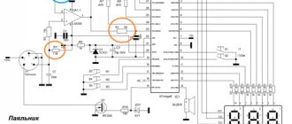
The thyristor control system in alternating and pulsating current circuits uses an infinite series of control pulses, synchronized with the network, and shifts the phase of the fronts of the control pulses relative to the transition of the network voltage through zero. A control pulse generated by a special device is supplied to the transition control electrode - thyristor cathode, which connects the electrical network to the load. Let us analyze the operation of such a system using the example of a temperature controller for the tip of an electric soldering iron with a power of up to 100 watts and a voltage of 220 volts. The diagram of this device is shown in Fig. 1.
The temperature regulator of an electric soldering iron in an alternating current network of 220 volts consists of a diode bridge on the KTs405A, a thyristor KU202N, a zener diode, and a control pulse generating unit. With the help of a bridge, the alternating voltage is converted into a pulsating voltage (Umax = 310 V) of positive polarity (point T1).
The generation unit consists of: - a zener diode, which generates a trapezoidal voltage for each half-cycle (point T2); — temporary charge-discharge chain R2, R3, C; - analogue of dinistor Tr1, Tr2.
The pulse voltage is removed from resistor R4 to start the thyristor (point 4).
The graphs (Figure 2) show the process of voltage formation at points T1 – T5 when the variable resistor R2 changes from zero to maximum.
Through resistor R1, the pulsating network voltage is supplied to the KS510 zener diode. A trapezoidal voltage of 10 volts is formed on the zener diode (point T2). It defines the beginning and end of the control section.
The parameters of the time chain (R2, R3, C) are selected so that during one half-cycle the capacitor C has time to fully charge. With the beginning of the transition of the network voltage Uc through zero, with the appearance of a trapezoidal voltage, the voltage on capacitor C begins to increase. When the voltage on the capacitor Uk = 10 volts, the analogue of the thyristor (Tr1, Tr2) breaks through. Capacitor C is discharged through an analogue to resistor R4 and, connected in parallel to it, the transition Ue - K of the thyristor (point T3) turns on the thyristor. Thyristor KU202 passes the main load current through the circuit: network - KTs405 - soldering iron spiral - anode - thyristor cathode - KTs405 - fuse - network. Resistors R5 - R6 serve for stable operation of the device.
The start of the control node is automatically synchronized with the network voltage Uc. The zener diode can be D814V,G,D. or KS510, KS210 for voltage 9 - 12 volts. Variable resistor R2 – 47 – 56 Kohm with a power of at least 0.5 watts. Capacitor C - 0.15 - 0.22 µF, no more. Resistor R1 - it is advisable to select from three resistors of 8.2 Kom, two watt, so that they do not heat up too much. Transistors Tr1, Tr2 – pairs KT814A, KT815A; KT503A, KT502A, etc.
If the regulated power does not exceed 100 watts, you can use a thyristor without a radiator. If the load power is more than 100 watts, a radiator with an area of 10 - 20 cm2 is required. In this pulse-phase method, the trigger pulse for the thyristor is generated within the entire half-cycle. Those. The power is adjusted almost from zero to 100%, when the phase angle is adjusted from a=0 to a=180 degrees. The graphs at point No. 5 show the voltage shapes at the load at selected phase angles: a = 160, a = 116, a = 85, a = 18 degrees. With a value of a = 160 degrees, the thyristor is closed during almost the entire half-cycle of the mains voltage (the power in the load is very small). At a = 18 degrees, the thyristor is open almost the entire half-cycle (the load power is almost 100%). In the graphs at point No. 4, during the opening of the thyristor, along with the appearance of the triggering pulse, the voltage drop across the open thyristor is added (Uп on the graph at point No. 4).
All shown voltage diagrams at points T1 - T5, relative to point T6, can be viewed on an oscilloscope.
style=»display:inline-block;width:728px;height:90px» data-ad-client=»ca-pub-5076466341839286″ data-ad-slot=»1544101189″>
Share