PractiCAM™ Computer-Aided Manufacturing System
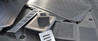
is focused on the production of products for ventilation systems from sheet and coil metal, as well as from pipe blanks.
PractiCAM™
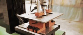
works with plasma and laser computer numerical control (CNC) machines, as well as stamping, scrolling and coordinate punching machines. The program has great functionality for cutting sheet metal, i.e. It is focused not only on the production of air ducts, but also flat parts, signs, weather vanes, roof elements, etc.
Compatible with any equipment
System PractiCAM™supports many models of plasma and laser CNC machines, interacts perfectly with machine control programs Mach3, Mach4 and Pumotix. It can also work with punching machines, spiral punching machines, jig punching machines, tube cutters and bar code readers. If your machine model is not yet in our library, then we will quickly write a post-processor for you completely free of charge, which will connect our program with your equipment.
Instant and accurate cost estimates
During your work, the system PractiCAM™continuously creates an accurate cost estimate of all parts manufacturing costs. The full calculation takes into account the cost of material, labor costs for manufacturing parts, the cost of all fastening elements (bolts, screws, tires, rivets, etc.), as well as the cost of various accessories (blades, rods, flaps, etc.). The American SMACNA standard tables are given as an example, but you can create your own standard tables for calculating labor costs at your enterprise, taking into account the specifics of your production.
Importing orders from 1C:Accounting program
In the 1C: Accounting program, you can create orders for cutting fittings, indicating their names, quantity, material, technological parameters, names of allowances, etc., and send them to the system PractiCAM™. Having received the order, the system
PractiCAM™
automatically finds the specified fittings in its libraries, applies the specified parameters to them and lays out their patterns on sheets of metal. After automatic installation, control commands for your equipment are generated, as well as various reports and labels.
Creating Labels
Mark parts in the system PractiCAM™easy and convenient. Various label templates are provided for your attention, but if they do not suit you for some reason, then you can create your own template. Add any information to your labels: your organization’s logo, barcodes, 3D images of parts, any part parameters you are interested in; edit these inscriptions in any style and font size. You can make a label for any fitting and flat part.
Geometry of parts
FieryCut includes geometry control to help you find errors faster. First, the user creates contours of parts from segments, polylines, arcs and circles. Splines and ellipses are pre-converted to polylines. List of features below:
- Automatic creation of workpiece contours;
- Support for unlimited nesting of contours;
- Support for open paths and text;
- Automatic geometry control during the creation of contours;
- Calculation of surface area and mass of workpieces;
- Save contour information to a DWG file.
Useful Specifications
Specifications (SNiPs) of the system PractiCAM™allow you to set all the features of your production standards when working with various products, make it possible to unify production, automate the entry of products for production and reduce the number of errors when entering data, thereby increasing your productivity, and with it your profit. You can create your own rules for the production of products that are used in your enterprise.
AutoPOL7 as part of a unified system for technological preparation of production
Thousands of users around the world enjoy working with AutoPOL7. AutoPOL7's user interface capabilities enable you to create a professional-oriented environment that helps increase design efficiency and increase productivity when working on sheet metal fabrication. AutoPOL7 has all the benefits that come with ARX technology from Autodesk, Inc. and the Mechanical Desktop API. In addition, AutoPOL7 provides the ability to transfer information and product simulation results to MSC Software's Dytran software package. Engineers have the opportunity to control the manufacturing process and manage the quality of the product already at the computer design stage. This allows you to significantly shorten the cycle from design to obtaining a real metal product and save significant money due to the absence of defects in the product, as well as due to the absence of the need for modification or re-manufacturing of equipment. But we will talk about this in the next article.
"CAD and Graphics" 6'2000
- development sheet metal parametric model deployment perforation interface editing documentation detail curvature surface cad sheet rai angle bending nurbs drawing compensation bending radius thickness sheet Kx-factor control program dxf CNC arx
Possibility of manual and automatic segmentation for large products
System PractiCAM™allows you to segment (break into separate components) large-sized products that do not fit on a sheet of metal. You can set segmentation rules for each product yourself or entrust this process to the program.
Benefits of our technical support:
- The best product support - at the request of users, we develop and add new software modules, create new fittings and parametric flat parts, and add new methods for cutting fittings to existing ones.
- Free training on how to use the program.
- Regular updates of PractiCAM™
- a new release is released at least once every 2 weeks. - Development and addition of new labels and reports, placing on them the information necessary for the user.
Currently, a new version of the PractiCAM™
.
Its main difference is that the program is now divided into many functional modules that can be turned on and off in various combinations, reducing or increasing the set of functions performed by the program. Depending on the number of included modules, the price of the program is determined. PractiCAM™
can still be purchased in its entirety with all its capabilities, but you can also purchase either one of the standard software packages (each of which is a stripped-down version of the
PractiCAM™
) or the standard package with additional options.
Standard PractiCAM™ packages:
PractiCAM™ for typical parts.
This package allows the user:
- Use libraries of parametric flat (two-dimensional) parts, create flat parts using a graphic editor.
- Work with a graphic model of the part, specify dimensions, material and thickness.
- Use multiple layers when creating a part.
- Create a library of materials used, indicating the material thickness and type (sheet, roll).
- Import files with the extension .dxf, .dwg (AutoCAD, Compass, etc.).
- Use automatic placement of parts on sheets of metal using various algorithms, including combined cutting.
- Lay parts on sheets of metal manually.
- Based on the installation results, generate and print installation maps.
- Based on the laying results, automatically generate a sequence of control (CNC) commands for the cutter.
- Set cutter parameters (table dimensions, positioning and orientation of the table, size and shape of the cut at the entrance and the cut at the exit, cutting and idle speeds, cut compensation, automatic placement of jumpers on parts).
- Determine the method of transmitting control commands to the cutter (via a file or COM port).
- Import/export files with the .pmx extension (PractiCAM™ program files).
PractiCAM™ for ventilation.
This package allows the user:
- Use libraries of shaped products (fittings).
- Work with a three-dimensional graphic model of a fitting, set dimensions, allowances, material, determine the method of cutting the fitting.
- Work with the library of fittings accessories, specify dampers, stiffeners, couplers, rotary blades.
- Use various marking notches, automatically generate bend lines, create marking lines.
- Create a library of materials used, indicating the material thickness and type (sheet, roll).
- Create a library of used allowances (connectors, locks, joints).
- Apply automatic laying of product patterns on sheets of metal using various algorithms, including combined cutting.
- Lay product patterns on sheets of metal manually.
- Based on the installation results, generate and print installation maps.
- Based on the laying results, automatically generate a sequence of control (CNC) commands for the cutter.
- Set cutter parameters (table dimensions, positioning and orientation of the table, size and shape of the cut at the entrance and the cut at the exit, cutting and idle speeds, cut compensation, automatic placement of jumpers on parts).
- Determine the method of transmitting control commands to the cutter (via a file or COM port).
- Automatically segment (cut into pieces) large patterns.
- Automatically add allowances when segmenting patterns.
- Create and edit seam allowances connecting segmented parts of patterns.
- Create tables for recalculating fitting section parameters and apply them when creating fittings.
- Import/export files with the .pmx extension (PractiCAM™ program files).
PractiCAM™ Classic.
This package combines the “PractiCAM™ for standard parts”
and
“PractiCAM™ for ventilation”
, providing all the possibilities that they have.
The list of additional options (program features) for packages is given in the table.
If you want to learn more about PractiCAM™, then at a time convenient for you, completely free of charge, we can conduct a demonstration of the program using Skype or Team Viewer, at the same time answering all your questions. Also, completely free of charge, we can write a postprocessor specifically for your machine controller and activate PractiCAM™ for 1 month so that you can evaluate all the capabilities of our program directly in your work. All you need to do is call us or write us an email, or leave your contact information by filling out the following form:
Video presentation of PractiCAM
Video presentation of PractiCAM for typical parts
Ream length when bending sheet metal
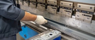
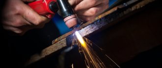
The material is bent by hand or on a bending machine, or with stamps under presses. Mostly small-sized parts are bent by hand.
On a bending machine, sheet blanks and parts are bent in a straight line from various materials and at various angles, both to obtain various profiles of box-shaped shapes and for flanging small widths (5-30 mm).
When bending the material, in order to avoid cracks, you need to monitor the bend radius, guided by the data in table. 4.
Table 4 - Bend radii in mm
| Material thickness | Electron | Duralumin | Aluminum, copper, brass | Steel |
| 0,3 | 1.5 | 1.5 | 0,6 | O.6 |
| 0,4 | 1,5 | 1,5 | 0.6 | 0,6 |
| 0,5 | 2.5 | 1.5 | 0,6 | 0.6 |
| 0,6 | 2,5 | 2.5 | 1.0 | 1,0 |
| 0,75 | — | — | 1,0 | |
| 0,8 | 4,0 | 2.5 | 1,0 | — |
| 1,0 | 4.0 | 2.5 | 1,5 | 1,5 |
| 1,2 | 4,0 | 4,0 | 1.5 | — |
| 1,25 | — | — | — | 2.5 |
| 1,5 | 6,0 | 4,0 | 2,5 | 2.5 |
| 1,75 | — | — | 2,5 | |
| 2,0 | 10,0 | 6,0 | 2,5 | 2,5 |
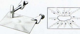
Before bending to a small radius, all parts are annealed. When bending, the material compresses and stretches (Fig. 194).
rice. 194.
Before the bend, the length of the line ab at the upper edge of the sheet blank at the bend is equal to the length of the line сd, located in the middle of the sheet blank, and the line mi at the bottom edge of the sheet blank.
After bending, the length of the arc ab is less than the length of the arcs c and pl.
This inequality shows that when bending, the material on the outside is stretched, and inside the curve it is compressed, and only the middle line CD does not change its length.
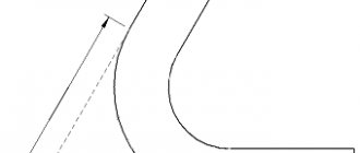
When bending sheet blanks from various materials to obtain a part of the required dimensions, the choice of permissible radii and determination of the lengths of the reamers (blanks) are of great importance.
Bending with rounding (Fig. 195) requires a shorter workpiece than bending without rounding (Fig. 196).