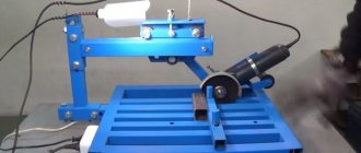
05/06/2018 Sheet metal bending is the process of deforming the shape of a workpiece by bending under the action of a press at the bend point. A metal sheet is placed between two plates or shaped rolls, depending on the machine model, and subjected to controlled deformation. Subsequently, the resulting workpiece is used as an element for the main product.
Modern equipment allows you to work with metals of any size and thickness, giving them a complex contour with several angles. If necessary, even a closed product can be created from rolled sheets.
Why is it important to take into account the profile length and press force when bending sheets?
Bending a sheet during work processes is always accompanied by deformations that occur in the structure of the metal. The inner surface of the sheet radius, under the action of a profile press, narrows and forms folds, and the outer surface is subject to tearing and stretching. If you go beyond the permissible values, breaks will appear in the crystal lattice of steel or aluminum, which will significantly deteriorate the properties of the metal. In the worst case, exceeding the permissible loads at the bend point can lead to complete rupture of the material.
To avoid this, experts perform preliminary calculations of the maximum ratios of metal thickness, profile length and bending radius. In CNC sheet bending machines, calculations are performed automatically. The operator just needs to set the primary parameters and the equipment will independently bend the sheet metal at a given angle.
But this method is not suitable for small and medium-sized mechanization methods. Here it is already necessary to make independent calculations using special formulas and tables.
Even if you take a stainless steel sheet with the exact dimensions of the future workpiece, then after deformation the finished product will be 7-9% shorter. And this is unacceptable in precision work. Therefore, before starting metalworking, specialists perform preliminary calculations using formulas.
Bending force calculator for press brake
25.09.18
The calculator for calculating the required force of a press brake allows you to calculate the required tonnage.
Useful for technologists and engineers for a general study of the capabilities of their equipment or for selecting a press brake to perform certain bending parameters.
Allows you to obtain general reference values in a matter of seconds without complex calculations, including for further selection of bending tools or placing bending orders.
Legend
F (force, tonnage), tons - the total required force for bending S (thickness), mm - thickness of the material (sheet) for bending V (opening), mm - opening of the matrix h (flange length), mm - minimum required length for direct residual flange of the part after bending L (bending length), mm - main bending length of the part (parallel to the width of the press brake) R (radius), mm - internal bending radius TS (tensile strength) - tensile strength of the part material for bending
The main formula used for calculation is:
Bending force F = (1.42 x TS x S2 x L)/1000 x V Inner radius R = (5 x V) / 32 For non-integer values, use a period rather than a comma
This calculator is intended solely for obtaining indicative reference information and cannot be an effective tool for accurate calculations and preparation of technical specifications. To obtain accurate and reliable values, you must consult with specialists.
Bending force table for press brake
The table below displays the approximate reference force according to die opening, minimum flange, metal thickness and radius. This table is valid for 1 meter of structural steel
| V | H min | R | 0,5 | 0,8 | 1 | 1,2 | 1,5 | 1,8 | 2 | 2,5 | 3 | 3,5 | 4 | 4,5 | 5 | 6 | 7 | 8 | 9 | 10 | 12 | 15 | 18 | 20 |
| 6 | 5 | 1 | 2,5 | 6,5 | 10 | |||||||||||||||||||
| 8 | 6 | 1,3 | 2 | 5 | 8 | 11 | ||||||||||||||||||
| 10 | 7 | 1,7 | 1,5 | 4 | 6 | 9 | 13 | |||||||||||||||||
| 12 | 9 | 2 | 3 | 5 | 7 | 11 | 16 | |||||||||||||||||
| 15 | 12 | 2,7 | 4 | 6 | 9 | 13 | 16 | |||||||||||||||||
| 20 | 15 | 3,3 | 4 | 7 | 10 | 13 | 19 | |||||||||||||||||
| 26 | 18 | 4,2 | 5 | 7,5 | 10 | 14 | 21 | |||||||||||||||||
| 30 | 22 | 5 | 6,5 | 8 | 12 | 19 | 24 | |||||||||||||||||
| 32 | 23 | 5,4 | 7,5 | 11,6 | 17 | 23 | 30 | |||||||||||||||||
| 37 | 25 | 5,8 | 10 | 14,5 | 20 | 26 | 33 | |||||||||||||||||
| 42 | 29 | 6,7 | 13 | 17 | 23 | 29 | 35,5 | |||||||||||||||||
| 45 | 32 | 7,5 | 16 | 21 | 27 | 33 | 48 | |||||||||||||||||
| 50 | 36 | 8,3 | 19 | 24 | 30 | 43 | 58 | |||||||||||||||||
| 60 | 43 | 10 | 20 | 25 | 36 | 49 | 64 | |||||||||||||||||
| 70 | 50 | 11,5 | 21 | 31 | 42 | 55 | 69 | |||||||||||||||||
| 80 | 57 | 13,5 | 27 | 37 | 48 | 60 | 75 | |||||||||||||||||
| 90 | 64 | 15 | 32 | 42 | 54 | 66 | 95 | |||||||||||||||||
| 100 | 71 | 17 | 38 | 48 | 60 | 86 | 134 | |||||||||||||||||
| 130 | 93 | 22 | 37 | 46 | 66 | 103 | 149 | |||||||||||||||||
| 180 | 130 | 30 | 33 | 48 | 75 | 107 | 133 | |||||||||||||||||
| 200 | 145 | 33 | 43 | 67 | 97 | 119 | ||||||||||||||||||
| 250 | 180 | 42 | 54 | 77 | 95 |
Useful formulas and data
We give examples of calculations for manual and semi-automatic bending
The length of the workpiece is determined by the formula:
L = Y1 + X1 + ,
where Y1 and X1 are the length of straight sections of the sheet profile; φ – external angle; r – bending radius; K – neutral line position coefficient (determined from technical tables) S – metal thickness.
To determine the length of a workpiece with several bend angles, the amounts in parentheses for each additional angle are added to the above formula. The workpiece is calculated using the sweep method by summing the length of all straight flanges Yn, Xn and adding the curvature radius.
The force of the press on the workpiece when bending sheet metal is determined by the formula:
P = 1.42 × S2 × L × ∂ʋ/V
where S is the thickness of the metal sheet profile; L – workpiece length size; ∂ʋ – tensile strength (reference value); V – matrix scan (technical parameter of the machine).
In practice, experts use ready-made templates and tables depending on the type and size of the metal profile. The exact parameters of the workpiece are selected from the tables and the maximum permissible press forces with deformation angles are selected.
Calculations using formulas are used only when working with non-standard workpieces and single orders, where it is important to maintain dimensions exactly to 0.1 mm.
TYPES OF SHEET METAL BENDING
There are mainly 3 types of bending:
- “free” or “air” bending;
- “bending on the basis” or “bending at close range” (sometimes also called “crimp”);
- "coining" or "sizing".
Let's consider each of these types separately.
FREE FLEXING
With this method, there is an air gap between the sheet of metal and the walls of the V-shaped matrix; the sheet remains “in the air” and does not come into contact with the walls of the matrix.
The punch acts on the metal from above at one point, and the matrix only at two points at the top of the V-shaped groove.
The bending geometry is formed only due to the depth of immersion of the punch into the matrix.
The width of the groove on the matrix is most often selected based on 10-15 metal thicknesses, and the tool has an angle much sharper than the part after bending.
Advantages of "free bending":
- High flexibility
: without changing bending tools, you can achieve any bending angle between the opening angle of the V-die.
For example, when using a 30° punch and a 30° matrix, you can obtain a bending angle on the part of 135°, 90°, 60°, 45°, etc.
- Lower tool costs
, you can get by with one set for many tasks. - Less
bending force required compared to other bending methods.
Disadvantages of "free bending":
- Less precise angles
. Due to the fact that the tool acts on the metal only at three points, the workpiece may behave unpredictably and the bending angle along the entire length will be uneven,
especially if there are residual stresses in the workpiece after cutting. Theoretical values are ±45 ́, but in practice it can reach several degrees.
- Lower repeat accuracy
, which is greatly influenced by differences in the quality of workpiece material. - Greater springback effect
due to greater elastic deformation. - Less versatility and bending quality
. The opening of the matrix during free bending of 10-15 sheet thicknesses is the reason for the increase in the minimum bend. Lack of contact with the walls of the matrix causes deformation of the holes ("eversion") located close to the bend line.
In what cases is “free bending” preferable:
- Large range of products, small-scale production.
- Different bend angles (including sharp ones).
- Minimum requirements for accuracy and quality of bends.
- The geometry of the final parts does not contain small minimum bends and internal bend radii equal to two thicknesses or more are acceptable.
BENDING BASED
Some people combine this bending method with “free bending”, but it has many of its own characteristics.
Unlike classical “air bending”, the workpiece in its final position is in contact with the walls of the V-groove and the bottom of the punch.
The required force is up to three times higher than with “free bending”. The matrix opening is selected from the range of 6-10 metal thicknesses.
Advantages of "based bending":
- More accurate angles
compared to air bending, theoretical values ±300. - Less springback effect and greater repeatability
due to greater impact on the metal and reduced elastic deformation. Despite this, a little spring remains, so if it is necessary to obtain 90° on the finished part, then the tool should be chosen 88°-85°. - Better bending quality
: the “turnout” of the hole decreases when the punch reaches the bottom position, relatively small openings of the dies allow making small minimum bends and fairly accurate internal radii equal to 1 to 2 metal thicknesses.
Disadvantages of "based bending":
- The greater required bending force
compared to “free” bending is not applicable for thick metals. - Less flexibility
compared to air bending; to achieve all the advantages of this method on a different profile or angle, a different tool is needed.
In what cases is “bending based on” preferable:
- Limited range of products, small-scale and mass production.
- Increased requirements for accuracy and quality of bends.
- The internal radii of bends should be from 1 to 2 metal thicknesses.
- One bend angle is often used, for example 90° and occasionally blunter ones.
- Optimal minimum bends.
COINING
This method consists of maximizing the space between the punch and the die in the final position.
The bending angle is determined by the force and geometry of the bending tool.
The pressure continues even when reaching the bottom point, due to this there is no elastic deformation, the metal sheet is plastically deformed under the pressure of the tool.
Advantages of "minting":
- Accuracy of bending angles
, despite the difference in thickness and material properties. - A small internal radius
, up to 0.5 times the thickness of the metal, may be unattainable by other methods. - Virtually no bounce back, maximum repeatability
. - Special designs available
, such as Z-bending, U-bending, multiple bends at a time, complex shapes.
Disadvantages of "minting":
- Maximum force requirements
, not only for the machine, but also for the tool and the fastening system. - Lack of flexibility
, one tool - one type of profile. - Only thin metal
, mainly used for thicknesses up to 2 mm. - Increased wear of tools and equipment
.
In what cases is “minting” preferable:
- Large-scale production.
- The highest demands on accuracy and repeatability.
- The internal radii of bends must be less than the thickness of the metal.
- It is necessary not to depend on the quality of the workpieces.
- A complex form of bends that cannot be obtained by other methods.
Let's consider a situation that often arises in bending production. This is especially true for small workshops that make do with small and medium-sized mechanization. By small and medium mechanization I mean the use of manual or semi-automatic sheet benders. The operator sums up the length of the shelves, obtains the total length of the workpiece for the required product, measures the required length, cuts and... after bending, receives an inaccurate product. Errors in the dimensions of the final product can be quite significant (depending on the complexity of the product, the number of bends, etc.). This is because when calculating the length of the workpiece, it is necessary to take into account the thickness of the metal, the bending radius, and the coefficient of the position of the neutral line (K-factor). This is exactly what this article will focus on.
So let's get started.
To be honest, calculating the dimensions of the workpiece is not difficult. You just need to understand that you need to take into account not only the lengths of the shelves (straight sections), but also the lengths of the curved sections resulting from plastic deformations of the material during bending.
Moreover, all the formulas have long been derived by “smart people”, whose books and resources I constantly indicate at the end of the articles (from there, if you wish, you can get additional information).
Thus, in order to calculate the correct length of the workpiece (part development), which ensures the required dimensions after bending, it is necessary, first of all, to understand which option we will use to make the calculation.
I remind you:
| Option 1 | Option 2 |
| Lt = A + B + BA | Lt = A + B – B D |
| Lt – total length of the flat workpiece; A and B – see picture; VA - allowance | Lt – total length of the flat workpiece; A and B – see picture; B D – deduction |
Thus, if you need the surface of shelf A without deformations (for example, for the location of holes), then you calculate according to option 1 . If the overall height of shelf A , then, without a doubt, option 2 is more suitable.
Option 1 (with allowance)
We will need:
a) Determine the K-factor (see Reference);
b) Divide the contour of the bending part into elements, which are straight segments and parts of circles;
c) Sum up the lengths of these segments. In this case, the lengths of straight sections are summed up without change, and the lengths of curved sections are summed up taking into account the deformation of the material and the corresponding displacement of the neutral layer.
So, for example, for a workpiece with one bend, the formula will look like this:
Where X 1 is the length of the first straight section, Y 1 is the length of the second straight section, φ is the external angle, r is the internal bending radius, k is the neutral line position coefficient (K-factor), S is the metal thickness.
Moreover, we will have to count the length of each shelf separately before setting the point of movement of the rear stop of the machine. I hope this is clear.
Thus, the calculation progress will be as follows..
Y1 + BA1 + X1 + BA2 + ..etc
The length of the formula depends on the number of variables.
Option 2 (with deduction)
In my experience, this is the most common calculation option for rotary beam bending machines. Therefore, let's look at this option.
We also need:
a) Determine the K-factor (see table).
b) Divide the contour of the bending part into elements, which are straight segments and parts of circles;
c) Calculate the required deductions. In this case, the lengths of straight sections are summed up without changing, and the lengths of deductions are subtracted accordingly.
Here it is necessary to consider a new concept - the outer boundary of bending.
To make it easier to imagine, see the picture:
The outer boundary of the bend is this imaginary dotted line.
So, to find the length of the deduction, you need to subtract the length of the curved section from the length of the outer boundary.
Thus, the formula for the length of the workpiece according to option 2:
Where Y 2 , X 2 – flanges, φ – external angle, r – internal bending radius, k – neutral line position coefficient (K-factor), S – metal thickness.
Our deduction ( BD ), as you understand:
Outer bending limit ( OS ):
And in this case, it is also necessary to calculate each operation sequentially. After all, the exact length of each shelf is important to us.
The calculation scheme is as follows:
(Y2 – BD1 / 2) + (X2 – (BD1 / 2 + BD2 / 2)) + (M2 – (BD2 / 2 + BD3 /2)) + .. etc.
Graphically it will look like this:
And yet, the amount of deduction ( BD ) must be calculated correctly when calculating sequentially. That is, we are not just cutting two. First we count the entire BD , and only after that we divide the resulting result in half.
I hope that I did not offend anyone with this remark. I just know that mathematics is forgotten and even basic calculations can be fraught with surprises that no one needs.
That's all. Thank you all for your attention.
When preparing the information, I used: 1. Article “BendWorks.
The fine-art of Sheet Metal Bending” Olaf Diegel, Complete Design Services, July 2002; 2. Romanovsky V.P. “Handbook of Cold Forging” 1979; materials from the English-language resource SheetMetal.Me (section “Fabrication formulas”, link: https://sheetmetal.me/formulas-and-functions/) print/PDF/e-mail
Bending theory
×
Bending to Contact: After selecting the desired V-channel, place material on both edges of the V-channel. After setting the stroke step, the upper tool will begin to move, bending will be carried out to the required value (30, 60, 75, etc.).
Please note that the material will experience stress during the bending process. Important values when choosing a V channel: - Sheets up to 3 mm - 6-8 x S - Sheets over 3 mm - 8-12 x SS - thickness of the bending sheet.
Note: These values are also taken into account when bending short material.
The resistance values, internal radius and other information required for the bending table are in the Instructions.
Example: Sheet thickness 3 mm, required channel width 25 mm, bending sheet 18 mm. The internal radius is 4.2 mm and the required resistance is 21 tons. Be careful about the following points when bending:
A – 3 points for efficient bending. These are both edges of the lower tool and the bending edge of the upper tool. B - Machined bending sheet (90). The upper tool must be under pressure on both sides until it reaches the channel of the lower tool. The advantages of this process are as follows: 1 - No need to use all the tonnage resistance Press.
2 – Possibility to bend appropriate sheet thicknesses. 3 – The same tool can be used at different bending levels.
The following tolerances must be taken into account when bending old shaped, backward shaped materials until they touch: a - bending with a pointed tool +/- 2b - bending with a standard tool +/- 3c - bending with a blunt tool +/- 5 Difference in levels total length, bending thickness until contact: Example: 2 mm sheet thickness with 140 bends.
Selected opening of channel V: V: 8 x s: 8 x 2: 16 mm As can be seen from the following table, if we take as a basis that the difference in the thickness of the total length of the material is 10%, then this means that the difference in level will be 2.5. The values given are calculated theoretically and in practice as described above.
ACCORDING TO DEHLER TABLE
PRESSING USING A TOOL
To achieve good results on precise profiles, the tools must be of very good quality. In this situation, high tonnage is required.
The pressing level on these machines is already set, so there is no need to make any settings yourself.
Advantages: Since the tendency of the material to return to its previous shape is minimized, the difference in levels will be minimal. Disadvantages: high tonnage and high bending require expensive tools.
The bending of the sheet is related to the value of the radius V of the channel and is not related to the thickness of the sheet and length. Under such conditions, the radius is less than the radius V of the channel.
SPECIFICATION FOR SHEET OF METAL HAVING A TENDENCY TO RETURN TO PREVIOUS FORM WHEN BENDING BEFORE CONTACT
As you know, metal sheets tend to take their previous shape due to the elasticity of the material. This is due to the following: A - proportions required by the standard B - Material consumption C - Material coating
C – Content
P: Pressure resistance (ton)L: Sheet length (mm)R: Resistance (kg/mm2)s: Sheet thickness (mm)V: Channel distance
Example:
Sheet length: 1000 mm Resistance: 42 kg/mm2
If V channel width: 8 x S is selected, then the following value is obtained.
With this formula, there is no need to carry out the remaining calculations to find the pressure resistance (tonnage). Length: 2500 mm Sheet thickness: 2 mm Resistance: 45 kg/mm2 Suitable pressure resistance 2.5 x 8 x 2: 40 tons, as the last example shows, a material rigidity of 40-45 kg/mm2 requires a resistance of 2.5 mm.
If the press brake is used beyond its capabilities, it may cause damage to the tool and material. When a sheet bends with a resistance of more than 40 kg/mm2, in this case, as practice shows, 10% must be added to the obtained value.
On hard material this value is 10-12 x S and due to the rigidity of the material the possibility of damage is prevented.
135 – Angle difference that can occur due to V-channel opening.
BENDING DIAGRAM
Capacity (tons) L: — Sheet length (mm) (L=1000mm) R: — Outer radius (mm) Tensile strength (kg/mm2) V: — Template distance P: — Required tonnage (tons) N: — Minimum bending sheet length (mm)S: — Sheet thickness (mm)
Basic 3D modeling operations > Sheet metal > Bending
To increase the rigidity of metal structures, a bent angle is used. It is also used for the construction of ventilated facades, in the production of sliding furniture and in many other areas. A bent angle is obtained from a cold sheet of metal using special equipment.
Options for making a bent corner:
- Bending on a hydraulic press - A strip of metal is placed on a lower table with a matrix. Under the influence of hydraulics, the punch moves from above. By applying pressure, a bent angle is obtained.
- Roll bending of metal - A sheet of metal is passed through rollers. Gradually moving them with each pass, a bent angle is obtained. With this bending method, it is possible to obtain surfaces of different shapes: cylindrical, spherical, conical and others.
The main condition for obtaining a bent corner is the absence of changes in the properties of the metal during processing. Both the first and second methods leave the metal structure at the bend sites unchanged. In this case, the metal sheet can have a thickness of up to 10 mm.
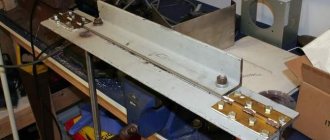
Metal bending on a hydraulic press
Sheet metal bending is a process of processing steel sheets, during which they are given the required shape.
The steel sheet is laid on the bending dies of the lower table. The steel sheet can have different thicknesses up to 10 mm and lengths up to 6 meters, depending on the purpose. Under the action of the pistons of the cylinders installed on the upper table, the punches approach the sheet metal laid on the dies of the lower table.
After the punch contacts the sheet metal, the pressure force begins to increase, and the punch is pressed into the metal sheet or sheet metal, deforming it first in the area of elastic deformation, and then in the area of plastic deformation, which allows a certain bending of the sheet metal to be obtained.
All those layers of metal that are located along the bending axis remain unchanged in size, therefore all calculations are carried out precisely with reference to these metal layers.
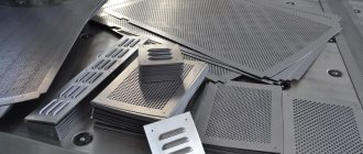
Bending of steel sheet is mainly used for the production of parts of various shapes using the cold bending method (example: bent angle, bent channel, etc.)
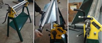
Metal bending on rollers
There are many known methods for bending workpieces in cold and hot states. It is mainly used to bend metal in a cold state on bending machines, hydraulic press brakes and three- or four-roll plate benders.
On sheet bending rollers, sheet steel is rolled to form cylindrical, conical, spherical and saddle-shaped surfaces and ring bending (rolling). On roller bending machines, angles, channels, pipes and I-beams are rolled.
In order to avoid structural changes, the appearance of significant hardening and complete loss of the plastic properties of steel, during cold bending of workpieces, the residual elongation should not exceed the limits of the yield strength.
When producing bent profiles on press brakes, the internal radii of curvature for carbon steel structures that bear a static load must be at least 1.2 sheet thicknesses, and for structures that bear a dynamic load, at least 2.5 sheet thicknesses. For sheet parts made of low-alloy steels, the minimum values of internal radii of curvature should be 50% greater than for carbon steel.
Sheet bending rollers have three or four horizontal rolls on which sheet steel is bent, the maximum width of which is 2100-8000 mm with a maximum thickness of 20-50 mm. The most common are three-roll rollers with a pyramidal arrangement of rollers. The two driven bottom rolls rotate in the same direction.
The upper roller moves in height and rotates as a result of friction between the rollers and the sheet being bent. One bearing of the upper roll can be tilted to the side to allow the bent part to be removed. Before bending cylindrical sheet parts, both ends of the sheet are folded onto the backing sheet.
The backing sheet should have a width that is 2 times the distance between the axes of the lower rolls, and the bending radius should be 10-17% less than the bending radius of the part, taking into account the elastic deformation of the steel.
The thickness of the backing sheet is usually taken to be 25-30 mm, but it must be at least 2 times the thickness of the sheet being rolled, and the power of the rollers must be sufficient to bend the sheet 3 times larger than the sheet being rolled.
Technological capabilities of the equipment
The market offers a huge number of various devices and machines for carrying out the process of bending steel materials. They make it possible to obtain profiles of complex shapes from steel sheets.
All types of metal bending equipment can be classified as follows:
- rotary machines: a flat sheet is launched between rotating rollers and bent;
- rotating machines: one end of the sheet is rigidly attached to a fixed beam, and the other to the rotating mechanism; the rotary beam is set in motion and the sheet bends;
- a press with a hydraulic (less often with a pneumatic) drive mechanism: sheet material is placed on the lower mold, and the second half of the mold is pressed from above with considerable force; As a result, the sheet is extruded and takes on the outline of a shape.
How is sheet metal bending carried out?
A technological operation such as sheet metal bending makes it possible to form a workpiece of the required configuration with minimal physical effort.
An alternative to bending rolled metal is the welding process, but in this case it takes much longer and is somewhat more expensive financially.
Sheet metal bending can be done manually or automatically, however, in both cases, the technology of the process itself remains unchanged.
In the case when bending is carried out on rolled products that have a large radius, as a rule, the neutral layer is located in the middle part of the thickness.
In turn, if the minimum radius is taken, then the above-mentioned layer is already shifted directly towards the compression region of the material.
In industrial production, sheet metal bending technology is carried out using special equipment, in which preliminary calculations are made and the corresponding GOST is taken into account.
The technology for bending rolled steel with your own hands has its own characteristics, despite the fact that the necessary calculations must also be made and GOST taken into account.
In this case, a special device is used, and in order to change the configuration of the metal sheet, it is necessary to make some effort and be sure to take into account the calculation.
Process technology: main stages
In order to bend rolled products, it is necessary to prepare special bending dies. In the press of the machine, the entire sheet of steel or alloy is placed until it stops. After this, it will be secured with clamps. Movement of sheets from side to side during the bending process is unacceptable. The bending itself occurs under the influence of the press.
The technology itself is not particularly complex. If rolled steel has sufficient ductility, it can be used to make one-piece structures of various types. The technology itself has become an excellent alternative to welding metal sheets. The absence of seams on the body parts guarantees them a greater degree of strength.
It is worth noting that modern bending equipment makes it possible to obtain bent sheets of excellent quality, which, due to their integrity, have a good appearance, are characterized by durability and reliability.