- Additional articles:
- OVERVIEW OF PROCESSING CENTERS OF OWN PRODUCTION
- CRITERIA FOR SELECTION OF MILLING EQUIPMENT
- 4-AXIS MILLING MACHINES
- MEDIUM MILLING MACHINES
- VERTICAL MACHINING CENTERS
Performing metalworking operations, including milling, requires technologically complex equipment, the choice of which depends on the availability of special engineering knowledge and practical experience. The variety of designs of milling machines requires the preliminary drawing up of a production flow chart, where all stages of product manufacturing are indicated with detailed characteristics:
- Types of technological operations.
- Execution sequence.
- Frequency of performing similar operations
- The required time to perform certain actions.
A clear idea of the future production process will allow you to avoid making mistakes when choosing equipment and eliminate the possibility of unnecessary waste of funds.
Milling machines: general information, classification, designation
Milling machines are designed for processing external and internal flat, shaped surfaces, shoulders, grooves, straight and helical grooves, splines on shafts, cutting gears, etc.
The designs of milling machines are varied. In general, milling machines can be divided into two main groups:
- general purpose or universal milling machines (vertical milling, horizontal milling, longitudinal milling
- specialized and special milling machines (slot milling, key-milling, rotary milling, copy milling, etc.)
The main shaping movements of milling machines are the rotation of the cutter (the main movement) and the feed movement, which is imparted to the workpiece or cutter.
The main movement and feed drives are operated separately. Auxiliary movements associated with the supply and removal of the workpiece to the tool are mechanized and carried out by a drive of accelerated movements.
The main elements of machine mechanisms are unified.
The main parameter characterizing general-purpose milling machines is the size of the working surface of the table.
Based on their design features, these machines are divided into:
- console machines (the table is located on a lifting console bracket)
- non-cantilever machines (the table is moved on a fixed frame in the longitudinal and transverse directions)
- continuous machines (rotary and drum)
- a — universal console horizontal milling machine
- b - universal cantilever horizontal milling machine
- c — universal universal non-cantilever milling machine
- g — cantilever vertical milling machine
- d - non-cantilever vertical milling machine
- e - non-cantilever horizontal milling machine
- g - longitudinal milling machine
- h — rotary milling machine
- and - drum milling machine
Cantilever milling machines are most common in single, small- and medium-scale production of rice. 119, a, b, c, d). Horizontal and vertical cantilever milling machines are the most common type of machines used for milling work. Cantilever milling machines get their name from the cantilever bracket (console), which moves along the vertical guides of the machine bed and serves as a support for the horizontal movements of the table.
A universal cantilever milling machine (Fig. 119, a) has a horizontal spindle 2 and a retractable trunk 1, on which a shackle 3 is installed, supporting a mandrel with a cutter; the console 4 moves vertically along the guide of the rack 5. The console contains a slide 6 and a rotary table 7 .
Horizontal cantilever milling machines (Fig. 119, a) have a horizontally located spindle 2 that does not change its location. The table can move perpendicular to the spindle axis in the horizontal and vertical directions. Unlike the Universal console milling machine, the work table does not rotate around a vertical axis.
The wide-universal cantilever milling machine (Fig. 119; b, c) in addition to the horizontal spindle, has a spindle head 1, which can be rotated on the trunk in two mutually perpendicular directions, due to which the spindle with the cutter can be installed at any angle to the table plane and to the workpiece . An overhead head 2 is mounted on head 1, intended for drilling, reaming, countersinking, boring and milling.
A vertical cantilever milling machine (Fig. 119, d) has a vertical spindle 3, which is located in a rotating spindle head 2 mounted on a stand 1.
Cantilever-free vertical milling machines (Fig. 119, e), used for processing blanks of large parts, have a slide 2 and a table 3, which move along the guides of the frame 1. The spindle head 5 moves vertically along the guides of the rack 6. The spindle 4 has vertical axial movements when installing the cutter. The table moves only in the longitudinal and transverse directions.
Cantileverless horizontal milling machines (Fig. 119, e), used for processing blanks of large-sized parts, have a slide 2 and a table 3, which move along the guides of the frame 1. The spindle head 5 moves vertically along the guides of the rack 6. The spindle 4 has axial movements at installing the cutter.
Longitudinal milling machines (Fig. 119, g) are designed for processing blanks of large-sized parts. On the frame 1, two vertical posts 6 are installed, connected by a cross member 7. Milling heads 3 with horizontal spindles and a traverse (cross member) 4 are mounted on the guide posts. Milling heads 5 with vertical spindles are mounted on the latter. Table 2 moves along the guides of racks 4.
Rotary milling machines (Fig. 119, h), designed for processing surfaces with end mills, have one or more spindles 3 for finishing and roughing. The spindle head 2 moves along the guides of the rack 1. The table 4, rotating continuously, imparts feed rotation to the workpieces installed on it. The table with slide 5 has an installation movement along the guides of the frame 6.
Drum milling machines (Fig. 119, i) are used in large-scale and mass production. The workpieces are installed on a rotating drum 2, which has a feed movement. Milling heads 3 (for roughing) and 1 (for finishing) move along the guides of the racks 4.
Purpose and scope
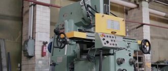
The 6P82 cantilever milling machine is designed to work with all types of cutters and perform a wide range of work:
- processing of side surfaces;
- creating protrusions and recesses;
- milling straight and curved grooves.
The model is designed for processing metals of different hardness and viscosity:
- cast iron;
- steels;
- bronze;
- alloys of non-ferrous metals.
Installation of devices increases the number of technological operations. On the machine, from one installation, the upper surface is processed, the ends are milled, holes are drilled and bored.
Important!
When installing a special tool, plexiglass, polyurethane and other dense materials are processed on the 6P82 milling machine.
The main products produced on the 6P82 model are rectangular-shaped parts of varying complexity: plates, gaskets, inserts, pillows and others.
Cantilever milling machines
Cantilever milling machines are the most common type of machines used for milling work. Cantilever milling machines get their name from the cantilever bracket (console), which moves along the vertical guides of the machine bed and serves as a support for the horizontal movements of the table.
The presence of a console, while providing cantilever-milling machines with a number of conveniences during maintenance, somewhat reduces the rigidity at the junction with the frame, therefore, in the designs of modern machines, the length of the console guides has been significantly increased, devices have been created for securing the moving parts of the machine, and the rigidity of the body parts has been increased.
Since for the most part the parts used in mechanical engineering fit into the dimensions of general-purpose cantilever-milling machines, the fleet of milling machines in mechanical shops is mainly equipped with horizontal and vertical milling machines of the cantilever type, and the fleet of tool and mechanical repair shops, in addition, also universal-milling and wide-universal-milling.
In addition, modifications are produced based on some basic models. For example, on the basis of vertical milling machines 6M12P and 6M13P, high-speed console vertical milling machines 6M12G1B and 6M13PB are produced. Based on the 6M82G horizontal milling machine, a faster model of the 6M82GB machine is produced. On the basis of universal milling machines 6N81 and 6N82, wide-universal milling machines 6N81A and 6M82Sh are produced. Widely versatile milling machines are currently widely used in individual and small-scale production to perform a variety of milling, boring and drilling work. These machines can be used to produce metal models, die-forms, templates, cams, etc.
The highly versatile 6N81A machine has a spindle head located on the trunk and rotating around a horizontal axis from 0 to 115°. In a horizontal position of the head, the machine operates like a horizontal milling machine, and in a vertical position, like a vertical milling machine.
The highly versatile 6M82Sh machine and the larger 6M83Sh machine, similar in design, have two spindles: one is horizontal, like a conventional horizontal milling machine, the second is located on the trunk and can be installed at any desired angle. The use of a dividing head and a round rotary table significantly expands the range of applications of these machines. For processing various types of surfaces, as well as large-sized workpieces that exceed the table area in size, the vertical spindle head is mounted on a retractable trunk and can be rotated at any angle in two mutually perpendicular planes. In this case, simultaneous operation of horizontal and vertical spindles is possible
The standard sizes of cantilever milling machines are usually characterized by the size of the working (mounting) surface of the table. Cantilever milling machines can have a horizontal , universal (widely universal) and vertical design with the same size of the working surface of the table. The combination of different versions of the machine with the same basic dimensional characteristics of the table is called the dimensional range of machines .
In the USSR, the production of cantilever milling machines of five standard sizes was mastered: No. 0; No. 1; No. 2; No. 3 and No. 4 , and a full range of machines was produced for each size - horizontal, universal and vertical. Each machine of the same size range had the same designation in the code, corresponding to the size of the working surface of the table.
Depending on the size of the working surface of the table, the following sizes of cantilever milling machines are distinguished:
| Size | Range of machines | Table size, mm |
| 0 | 6Р10, 6Р80, 6Р80Г, 6Р80Ш | 200 x 800 |
| 1 | 6N11, 6N81, 6N81G; 6Р11, 6Р81, 6Р81Г, 6Р81Ш | 250 x 1000 |
| 2 | 6M12P, 6M82, 6M82G; 6Р12, 6Р82, 6Р82Ш; 6T12, 6T82, 6T82G, 6T82Sh | 320 x 1250 |
| 3 | 6M13P, 6M83, 6M83G; 6Р13, 6Р83; 6T13, 6T83, 6T83G | 400 x 1600 |
| 4 | 6M14P, 6M84, 6M84G | 500 x 2000 |
In accordance with the size of the table, the overall dimensions of the machine itself and its main components (bed, table, slide, console, trunk), the power of the electric motor and the magnitude of the greatest movement (stroke) of the table in the longitudinal direction, the slide in the transverse direction and the console in the vertical direction change.
Compliance with safety regulations
Safe operation on the 6Р82Ш universal milling machine is ensured by:
- Availability of a duplicated control system;
- Quickly disconnect equipment from power by pressing just one button;
- The use of protective barriers to prevent chips and cutting fluid from entering the operator;
- Periodic and qualified maintenance.
Persons who have completed the necessary industrial training and passed the qualification exam for the category of milling operator are allowed to work on the machine.
The general requirements that determine the rules for care and maintenance of the 6Р82Ш milling machine are given in GOST 12.2.009-99.
Cantilever milling machines produced in the USSR and CIS
| Series | Size | Manufacturer | Year | Model |
| 6 | 2 | SFFS | 1932 | 682 |
| 6B | 0 | |||
| 1 | ||||
| 2 | SFFS | 1937 | 6B12, 6B82, 6B82G | |
| 3 | ||||
| 6K | 0 | |||
| 1 | DZFS | 6K11, 6K81, 6K81G, 6K81SH | ||
| 2 | SFFS | 6K12, 6K82, 6K82G, 6K82SH | ||
| 3 | SFFS | 6K13P, 6K83, 6K83G, 6K83SH | ||
| 6H | 0 | Zalgiris | 1969 | 6N10, 6N80, 6N80G, 6N80Sh |
| 1 | DZFS | 1970 | 6N11, 6N81, 6N81G, 6N81A, 6N81D | |
| 2 | SFFS | 1951 | 6N12, 6N82, 6N82G | |
| 3 | GZFS, VSW | 1951 | 6N13, 6N13F3, 6N83, 6N83G, 6N13GA | |
| 6M | 0 | Zalgiris | 6M10, 6M80, 6M80G, 6M80Sh | |
| 1 | DZFS | 1971 | 6M11, 6M11K, 6M81, 6M81G, 6M81Sh, 6M81Sh-1, 6M81Sh-1F1, 6M81ShF2 | |
| 2 | SFFS | 1961 | 6M12P, 6M12PB, 6M82, 6M82G, 6M82GB, 6M82Sh | |
| 3 | SFFS | 1961 | 6M13P, 6M13PB, 6M83, 6M83G, 6M83Sh | |
| 6Р | 0 | Zalgiris | 1973 | 6Р10, 6Р80, 6Р80Г, 6Р80Ш |
| 1 | DZFS | 6Р11, 6Р11К, 6Р11Ф3, 6Р81, 6Р81Г, 6Р81Ш | ||
| 2 | SFFS | 1972 | 6Р12, 6Р12К, 6Р82, 6Р82Г, 6Р82Ш | |
| 3 | GZFS, VSW | 1972 | 6Р13, 6Р13Б, 6Р13Ф3, 6Р13Ф3-3, 6Р83, 6Р83Г, 6Р83Ш | |
| 6T | 0 | Zalgiris | 1986 | 6Т10, 6Т80, 6Т80Ш |
| 1 | ||||
| 2 | SFFS | 1985 | 6T12, 6T82, 6T82G, 6T82Sh | |
| 3 | SFFS | 1985 | 6Т13, 6Т83, 6Т83Г, 6Т83Ш | |
| 6D | 0 | DZFS | 1987 | 6D10, 6DM80Sh |
| 1 | DZFS | 1990 | 6D81, 6D81, 6D81G, 6D81SH | |
| 2 | DZFS | 6D12, 6D12F20, 6D12F3, 6D82, 6D82G, 6D82SH | ||
| 3 | DZFS | 6DM83SH |
The main manufacturers of milling machines in the USSR and Russia:
VSW - Votkinsk Machine-Building Plant. Currently - Votkinsk Plant, JSC
GZFS - Gorky Milling Machine Plant. Currently - ZFS Milling Machines Plant, LLC
DZFS - Dmitrov Milling Machine Plant. Currently - Dmitrov milling machine plant DZFS, LLC
UZTS - Ulyanovsk plant of heavy and unique machine tools UZTS. Currently - Ulyanovsk Plant of Heavy and Unique Machine Tools UZTS, LLC
VSZ - Voronezh Machine Tool Plant.
Zalgiris – Vilnius Machine Tool Plant
Symbols of serially produced metal-cutting machines
In more detail - Symbols of commercially produced milling machines.
6
— milling machine (group number according to
ENIMS )
D
– series (generation) of the machine (B, K, N, M, R, T), for example, 682, 6B82Sh, 6K82Sh, 6N82Sh, 6D81Sh, 6R82Sh, 6T82Sh
8
– subgroup number (1, 2, 3, 4, 5, 6, 7, 8, 9) according to the ENIMS classification (8 - horizontal milling)
1
– machine version – standard size (0, 1, 2, 3, 4) (1 – work table size – 250 x 1000)
Letters at the end of the model designation:
G
– horizontal cantilever milling machine with a fixed table
TO
– a machine with a copying device for processing curved surfaces
B
– a machine with increased productivity (increased range of spindle speeds, increased power of the main movement motor).
P
– increased accuracy of the machine - (n, p, v, a, s) according to GOST 8-82
Sh
– widely universal machine
F1
– a machine with a digital display device (DRO) and preset of coordinates
F2
– machine with CNC positional numerical control system
F3
– machine with contour (continuous) CNC system
F4
– multi-purpose machine with CNC contour system and tool store
Rubicon, LLC
List of controls
The 6Р82Ш machine can operate in manual and automatic modes. In the latter case, the cutters can additionally move along a closed rectangle, slow down the feed of the tool or workpiece, and turn on the drive for supplying lubricant and cutting fluid.
The governing bodies include:
- Handles for switching the operating modes of the feed mechanism and gearbox;
- Buttons for turning nodes on and off;
- Handwheels for manual table movement;
- Control panel for spindle rotation modes;
- Handles for moving the movable panel;
- Control panel for the movement of the movable slide;
- Machine emergency shutdown buttons.
The principle of controlling the operation of a 6Р82Ш milling machine is based on the combined use of digital indicator readings (table position, spindles) and manual control of the main components using graduated handwheels. Handles are provided on both side surfaces of the stand. The layout of the machine allows its modernization with the installation of an automated control system.
