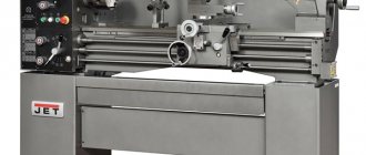
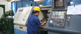
Using a lathe of one of the modern models, you can perform a fairly large list of technological operations for metal processing. But mainly such equipment is used to process the external and internal surfaces of workpieces having a cylindrical, conical and shaped configuration.
Modern lathe
History of the appearance and development of equipment
According to historians, lathes (or rather, the primitive ancestors of such devices) were invented and began to be used by man in the middle of the 7th century BC. Of course, such a device had a simple design, but it made it possible to effectively process wood or bone products. In order to carry out such processing, the part was clamped in two centers, which were mounted coaxially with each other. It was rotated manually, and the cutting process was carried out using a hand cutter, which was manipulated by a separate “operator”. Thus, the product was given the required shape and size.
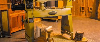
The next stage of development that the equipment of the turning group underwent was equipping it with a drive necessary to impart rotational movement to the part. Initially, a bow string was used as such a drive, which was looped over the workpiece. And a little later (in the 14th century) a foot drive for turning equipment was invented.
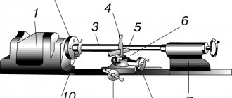
Antique foot operated lathe
The design of such a drive, very reminiscent of the drive mechanism of a foot sewing machine, consisted of a fixed cantilever wooden pole connected to the workpiece using a strong rope. When you pressed the pole with your foot, the rope was stretched, which led to the rotation of the workpiece by 1–2 turns. After the leg was removed from the pole, the rope was released and rushed upward, which entailed the rotation of the workpiece in the other direction.
Despite their simple design, such lathes already made it possible to perform processing with fairly high quality. Their advantage was that servicing the devices was very simple.
A. Nartov's turning and copying machine, 1729
The lathe of the 16th century group already had a steady rest and centers made of metal in its design, which made it possible to use it for processing workpieces with complex configurations. However, due to the low power of such a device, it was not yet possible to use it for turning metal workpieces.
The history of the lathe received a strong impetus in the 1700s, when the Russian Andrei Nartov created a device on which a mechanical support was installed. It should be noted that it was this innovation that served as the strongest impetus for the development of all equipment designed for processing metal workpieces. A major contribution to the development of turning units was made by French engineers, who by the middle of the 18th century created a device that was highly versatile. By the end of this century, French industry began to use a specialized unit on which it was possible to cut threads on metal screws.
Maudsley Lathes (click to enlarge)
The year 1794 is considered to be a truly breakthrough in the development of turning equipment, when Henry Maudsley created a machine that served as the basis for the further development of all turning units. What is noteworthy is that the company founded by Maudsley was also engaged in the production of dies and taps, with the help of which threads were cut on his equipment.
They began to think about automating a lathe in the 19th century, and American engineers took the lead in this matter. This process followed the path of equipping units with additional automation elements, which ultimately led to the creation of the first machine with a turret. It was on the basis of such devices that later they began to create universal automatic machines, the first of which (the Spencer machine) was presented to the public in 1973.
First mentions
In the 700s AD. a unit was created that partially resembles a modern lathe. The story of its first successful launch begins with wood processing by rotating the workpiece. Not a single part of the installation was made of metal. Therefore, the reliability of such devices is quite low.
At that time, the lathe had low efficiency. The history of production has been reconstructed from surviving drawings and drawings. It took 2 strong apprentices to unwind the workpiece. The accuracy of the resulting products is low.
History dates information about installations vaguely reminiscent of a lathe to 650 BC. e. However, the only thing these machines had in common was the processing principle - the rotation method. The remaining nodes were primitive. The workpiece was literally set in motion by hand. Slave labor was used.
The models created in the 12th century already had some kind of drive and could be used to produce a full-fledged product. However, there were no tool holders yet. Therefore, it was too early to talk about the high accuracy of the product.
Classification of turning equipment
The classification of lathes, which was developed back in Soviet times, classifies such units into the first category of equipment intended for processing metal workpieces. According to this classification, all types of lathes are classified into one of the following categories:
- automatic and semi-automatic turning units with one spindle;
- multi-spindle machines: automatic and semi-automatic;
- revolver models;
- cutting group machines;
- carousel models;
- frontal and screw-cutting equipment;
- multi-cutting and polishing units;
- specialized machines, which can be conventional or automatic;
- special purpose devices.
Main types of turning work
According to the degree of processing accuracy, the following types of lathes are produced:
- special accuracy - C;
- high accuracy - B;
- normal accuracy - N;
- especially high accuracy - A;
- increased accuracy - P.
Its functionality and, accordingly, its scope of application depend on the category to which the lathe belongs. You can also learn about the main technical capabilities of the machine by its marking, which includes the following:
- the initial number “1”, indicating that this is a lathe and not any other;
- a second digit indicating the type to which the turning unit belongs;
- the third digit (and in some models the fourth) is the most basic parameter of the machine, which characterizes the height of its centers.
Explanation of lathe markings (click to enlarge)
The marking of such units also contains letter designations that determine its design features: the level of its automation, accuracy, modification, and equipment with a CNC system. For example, the marking of the 1I611P lathe model is deciphered as follows: the letter “I” indicates that this is a screw-cutting lathe device; the letter “P” is a high-precision machine; The height of the centers for this model corresponds to 110 mm. You can guess what category of lathe you have in front of you by looking at the photo of the model.
Types of turning equipment
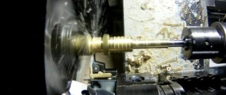
Turret lathes are designed for products that require processing of several surfaces using various tools. In order not to have to install and configure each tool, turret heads are installed on such machines, which can have two or more slots for placing tools. Of course, servicing such a lathe is much more difficult than a conventional model, but this is fully compensated by the functionality of this unit. For example, popular models of such machines are 1E316P, 1G340PTs, 1P371, 1A341.
A rotary lathe is one of the types of lathes
Rotary turning machines are designed for processing workpieces characterized by a short length, significant weight, and large outer diameter. These include dimensional gears, flywheels, etc. The functionality of such lathes (for example, models 1512, 1541, 1550, 1L532 and others) allows them to perform various types of turning work: turning, boring, cutting grooves, end processing, etc. And if you equip such turning units with additional devices, they will become even more versatile: with their help it will be possible to perform some milling operations, cut threads, grind and perform a number of other technological actions.
Working parts of a multi-spindle machine
Multi-spindle machines belonging to the turning group are necessary for performing complex technological operations in mass production conditions. Workpieces that can be processed on such machines can be in the form of pipes, hexagonal, square and round rods, shaped profiles, etc. This technique is distinguished by its high rigidity of design and powerful drive, which allows processing with high productivity.
What is important is that such complex and functional equipment is maintained in exactly the same way as a conventional machine. The list of technological operations that can be performed on such a unit is quite extensive: boring, roughing and shaping, cutting and rolling threads, etc. The most popular models of such turning equipment are 1P365 and 1B140 machines.
Screw-cutting lathe 16K20
Common models of turning machines, which gained wide popularity back in Soviet times, are screw-cutting lathes. Such machines, which can be found not only in almost any industrial enterprise, but also in school workshops, have gained their popularity due to the fact that with their help they can effectively perform a large list of technological operations.
Each such machine, regardless of the model, has a standard design consisting of the same type of components. Along with their functionality, screw-cutting lathe models are characterized by high safety, ease of operation and maintenance, which makes it possible to use them as units for equipping school workshops since the times of the USSR. The most famous and popular models of such turning equipment are machines 16K20, 16K50, 16B16A and 16P16P.
At enterprises that produce their products in large series and use blanks from shaped profiles and calibrated rods in production, automatic lathes are actively used. Such machines, which primarily perform turning operations in the longitudinal direction, cope with equal success in processing workpieces made of various metals: super-hard alloys, soft copper, etc.
On the domestic market, lathes are represented mainly by models from foreign manufacturers (Japan, South Korea, etc.). There are also some domestically produced models, for example 1M10DA.
Longitudinal turning machine 1M10DA
Main nodes
Lathes are ideal for machining 3D parts using rotary cutting. An overview of a modern machine contains the parameters and characteristics of the main components:
- The bed is the main loaded element, the frame of the machine. They are made from durable and hard alloys; perlite is mainly used.
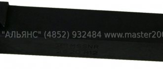
- A support is an island for mounting rotating tool heads or static tools.
- Spindle - acts as a workpiece holder. The main powerful rotation unit.
- Additional components: ball screws, sliding axes, lubrication mechanisms, coolant supply, air intakes from the working area, coolers.
A modern lathe contains drive systems consisting of complex control electronics and a motor, usually a synchronous one. Additional options allow you to remove chips from the working area, measure the tool, and supply coolant under pressure directly to the cutting area. The mechanics of the machine are selected individually for production tasks, and the cost of the equipment depends on this.
The support contains units for placing bearings, which are mounted on a ball screw (ball screw). Elements for contact with the sliding guides are also mounted on it. Lubricant in modern machines is supplied automatically, and its level in the tank is controlled.
In the first lathes, a person moved the tool and chose the direction of its movement. In modern models, all manipulations are carried out by the controller. It took several centuries to invent such a knot. Electronics have greatly expanded processing capabilities.
Design features of lathe group machines
All machines designed for turning workpieces made of metal and other materials have standard structural elements in their design:
- bed - the supporting element of the turning unit on which all the elements of its structure are installed;
- apron (in this element of the lathe, the movement of the roller or lead screw is converted into the movement of its support);
- spindle headstock, on which the spindle of the device is located, and in its inner part there is a gearbox;
- caliper (in this element of the machine the cutting tool is fixed, the caliper is also needed in order to ensure longitudinal and transverse feed of the tool, carried out with the specified parameters; the design of the caliper must include a lower carriage, and some models have several of them, on the top of which a holder is attached for turning tools);
- feed box (using this structural element, movement is transmitted from the lead screw or roller to the machine support);
- the electrical part of the machine structure, which includes a drive electric motor, the power of which can vary significantly between different machine models, as well as elements that control the electrical equipment of the device (naturally, this part of the turning unit must meet safety requirements).
Main components of a lathe
All structural elements of the machine rest on two pedestals, which perform a load-bearing function and also ensure that the workpiece is placed at a height convenient for the operator. Such cabinets, distinguished by their massive design, can be seen in the photo of a lathe of any model.
The main part of the structural elements of turning equipment is unified, which makes it possible to quickly and cost-effectively carry out their maintenance and repair.
Lathe support design
Machine drive shafts
Example of lathe control layout (click to enlarge)
Metal parts
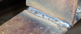
The main task of the machine tool inventors was to increase the rigidity of the units. The beginning of technical re-equipment was the use of metal centers that clamp the workpiece. Later, gear transmissions made of steel parts were introduced.
Metal parts made it possible to create screw cutting machines. The rigidity was already sufficient for processing soft metals. Individual components were gradually improved:
- workpiece holder, later called the main unit - spindle;
- the conical stops were equipped with adjustable mechanisms to change the position along the length;
- working on a lathe became easier with the invention of the metal tool holder, but constant chip removal was required to increase productivity;
- The cast iron bed increased the rigidity of the structure, which made it possible to process parts of considerable length.
With the introduction of metal components, it becomes more difficult to unwind the workpiece. The inventors thought about creating a full-fledged drive, wanting to eliminate manual labor. The transmission system helped to carry out the plan. For the first time, a steam engine was adapted to rotate workpieces. It was preceded by a water engine.
The uniform movement of the cutting tool was carried out by a worm gear using a handle. This resulted in a cleaner surface of the part. Replaceable blocks made it possible to implement universal work on the lathe. Mechanized designs have been refined over centuries. But to this day, the operating principle of the units is based on the first inventions.