Application and advantages of rotary turning machines
Using rotary lathes, they process large flywheels, gears and other similar parts. The technical capabilities of such devices allow the following technological operations:
- turning and boring of workpieces having a cylindrical and conical configuration;
- cutting ends and processing them;
- processing of inclined surfaces;
- formation of ring-type grooves on the surface of the part;
- drilling;
- deployment;
- countersinking.
Vertical turning lathes are also equipped with special devices, supplied separately, which allow the following operations to be performed on this equipment: milling, chiselling, cutting threads of various types, processing shaped surfaces using an electrocopier, grinding, processing workpieces using stops. The characteristics of rotary lathes make it possible to process workpieces made from ferrous and non-ferrous metals with a diameter of up to 25 m.
Single column machine 1516
The main movement in the machines of the group under consideration is performed by the work table (faceplate), on which the part is fixed. The feed movement, as in all lathes, is carried out by a support in rotary turning equipment.
Thanks to its design features, the rotary machine is characterized by high safety, reliability, ease of maintenance and operation. Among the most significant advantages of such equipment, the following are worth highlighting:
- accuracy and high quality of processing, requiring a minimum percentage of defects;
- ease of equipment control, which is especially typical for machine models equipped with a CNC system;
- high speed of all technological operations.
However, as many experts note, the most important advantages of rotary lathes include the safety of their operation.
How do rotary lathes work?
The most significant element of the design of machines of the rotary-turning group is their work table, on which the faceplate is located. This is where the workpiece requiring processing is fixed. The working surface of the table is located in a horizontal plane, which simplifies the process of installing workpieces with significant dimensions and weight on it.
Depending on the model and design features, one- and two-column machines are distinguished among the rotary-turning machines. On the first, a faceplate with a diameter of up to 1600 mm is installed. Such units are used to work with workpieces with a diameter of up to 1500 mm. More impressive characteristics are provided by two-column units, on which a faceplate with a diameter of up to 25,000 mm can be installed, which makes it possible to process very large workpieces.
On the frame of the two-column unit, located in a vertical plane, there are two guides along which the crossbar moves with two supports mounted on it - a revolving one and a boring one. The machine supports, in turn, move along the horizontal guides of the crossbar.
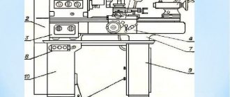
The main components of rotary turning equipment using the example of machine 1512
The revolving support, which can move in vertical and horizontal directions, includes a longitudinal carriage and a slider that moves along a vertical axis. It is on the slide that the turret head with special holes for installing the cutting tool is mounted. With the help of a turret support and a cutting tool fixed in it, technological operations such as processing external surfaces, drilling holes, and trimming the ends of a part are performed.
The design of the boring support includes a longitudinal carriage on which the rotating mechanism is mounted. The latter has a slider with a tool holder installed on it. Using a boring carriage and tools mounted in it, conical surfaces are machined, holes are bored, and internal grooves are cut.
On single-column machines of the rotary-turning group, a side support is installed, consisting of a longitudinal carriage, a slider and a tool holder. The purpose of such a support is to ensure the processing of external surfaces.
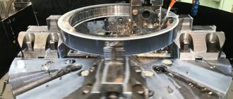
Faceplate of rotary machine
The use of two cutting tools simultaneously during the processing process is especially important in the field of heavy engineering - in the production of hydraulic turbines, generators and other parts of large dimensions and weight.
Requirements for an application for rotary turning
To quickly assess the time frame and cost of metal bending work, we recommend sending an application with the most complete information:
- Company name, contact person, contact telephone number;
- Drawings in dxf, dwg, pdf formats.;
- The exact name of the part, the thickness and grade of the metal, the number of parts being manufactured;
- Each part is a separate drawing file with provided dimensions (for control during manufacturing).
Rotary turning is very popular in the metalworking industry. Modern equipment is used for processing external and internal surfaces, as well as for the preliminary and final stages of manufacturing parts. The wide functionality of this equipment allows you to implement quite difficult tasks in the shortest possible time.
Main features of the equipment
When choosing a rotary-turning machine, you should take into account the following characteristics:
- machine power;
- number of speeds and speed range of the faceplate;
- angle of rotation of the vertical support slider;
- the magnitude of the maximum movement of equipment supports in horizontal and vertical directions;
- maximum dimensions of the part being processed (height, diameter);
- maximum amount of movement of the crossbar (for two-column machines);
- faceplate dimensions.
Processing on rotary-turning machines is carried out at high speeds. This is permissible because the workpiece and spindle do not experience significant cantilever loads, since the faceplate is fixed to the work table in a special way.
In addition to the main movement and the feed movement, the machines of this group use additional movement performed by the crossbar (also called the traverse). With its help, the cutting tool is brought to the surface of the workpiece.
As mentioned above, large-diameter parts (16.5–25 m) are processed on two-column rotary-turning machines, and single-column units are used for workpieces with smaller dimensions. CNC systems are installed on single-column carousel devices, which allows the use of such equipment for processing parts with a complex configuration, characterized by the presence of both straight and curved generatrices.
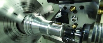
CNC turning lathe
What is typical is that on CNC-equipped vertical turning machines a side support is not installed: all technological operations on them are performed through the use of a turret support, the operation of which, like the main movement drive, is controlled by a special program. Entered into the machine control unit, it is responsible for performing such technological operations as:
- selection and installation of the required rotation speed of the equipment faceplate;
- turning the turret head to the position required for processing and fixing it in this position;
- control of the feeds made and the position occupied by the working devices;
- setting the cutting tool in the zero position;
- control of movements made by working tools.
Operating principle
When considering the description of the rotary group machines, attention is paid to which units will receive rotation or reciprocating motion. Vertical lathe with or without CNC has the following features:
- The supports move thanks to the feed movement. The cutting tool must be mounted in supports; their position can be changed manually or through automatic feed.
- The rotation is transmitted to the faceplate. The equipment under consideration is characterized by the fact that the main drive is connected precisely to this structural element in which the workpiece is fastened.
- There are a very large number of additional movements that can simplify the processing process. An example is a turret in which a tool is installed for boring or performing other operations. The tool is changed by rotating it around its axis. When cutting threaded surfaces, additional equipment is installed; in some models, the table also receives reciprocating motion, and rotation is transmitted to the tools. The movement is also transmitted to the traverse.
However, the operating principle of a CNC lathe is somewhat different, which we will discuss in detail later.
Models of domestic rotary turning equipment
The history of domestic rotary-turning machines began in 1935, when at the Krasnodar Machine Tool Plant named after G.M. Sedina, the first such unit was produced. It should be noted that this plant has long been considered the most famous and authoritative manufacturer of rotary-type lathes. The plant's products - high-quality and reliable rotary-turning machines - were actively used throughout the Soviet Union. Many of these devices can still be found in industrial enterprises.
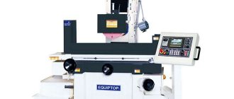
Machine 1512
The most popular equipment models from this manufacturer include machine 1516. This model of a single-column machine (along with model 1512) belongs to the category of universal turning-borot devices designed for processing workpieces made of ferrous and non-ferrous metals in small-scale and mass production.
The technical characteristics of the machines of both models mentioned above ensure the performance of almost any turning operations, but these devices are used primarily for turning and boring:
- cylindrical surfaces;
- flat ends of workpieces;
- conical surfaces.
You can find some modifications of these machines on which the manufacturer installed self-centering type faceplates. Naturally, the technological capabilities of equipment with such faceplates are much wider than those of conventional models.
Produced at the plant named after G.M. Gray hair and two-column lathes of the rotary-turning group. A striking example here is model 1525. Among the notable characteristics of the machine of this model, it is worth noting the following: the ability to change the direction of rotation of the faceplate (reverse); the presence in the design of two upper rotary calipers. The drive of the main movement of the model 1525 machine was equipped with a two-stage gearbox and an electric motor, the shaft speed of which can be adjusted. Two electromagnetic couplings in the machine design are responsible for selecting the rotation speed range of the faceplate, and the rotation speed of the main electric motor shaft is steplessly regulated through a special electrical circuit.
All of the above machine models were also produced with CNC, then their markings looked like this: 1512F2, 1516F2, 1525F2. As a control system on these devices, domestic software systems (P32-3M, N55-2) or electronic equipment from Bosch (Germany) and Alcatel (France) were installed.