Orbitalum Tools is your reliable partner in the field of pipe cutting and facing, as well as automatic orbital welding of industrial pipelines.
Types of welding - Gas shielded arc welding
Gas shielded welding is one of the most common fusion welding methods. Compared to other methods, it has a number of advantages, the main ones of which are: the ability to visually, including remotely, monitor the welding process; wide range of operating parameters of welding mode in any spatial positions; the possibility of mechanization and automation of the process, including the use of robotics; highly effective protection of molten metal; the ability to weld metals of different thicknesses ranging from tenths to tens of millimeters.
The essence of the method
Welding of workpieces in a shielding gas environment is one of the subtypes of arc bonding, but here argon, nitrogen, oxygen, etc. are supplied to the melting point. If there is a need to integrate low-carbon or alloy steel, 1-5% oxygen is added to the gas. Such proportions reduce the critical tension, which protects against the formation of pores and improves the quality of adhesion.
For production with a melting rod, argon and 10-20% carbon dioxide are mixed. This gives the same indicators as in the previous case, however, it adds constancy to the arc and protects the area from drafts. The technique itself is popular mainly in the processing of thin sheets of metal.
During deep smelting, CO2 and 20% O are used. The mixture is endowed with increased oxidizing properties, gives a good shape, and protects the slabs from porosity. Similar indicators are typical for other compounds, but each procedure has an individual approach, which will depend on the situation, the thickness of the object and other parameters.
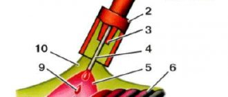
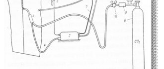
Scheme of gas-shielded arc welding
Despite the highest results, the joining plane must be carefully processed using the following techniques:
- alignment;
- rust removal;
- removal of nicks;
- heating.
If the preparatory manipulations are performed incorrectly, this will lead to weld defects.
Welding technology
Gas-shielded arc welding involves the use of two approaches: non-consumable and consumable pins. The first type makes a weld by melting the corners of the alloy. In the second case, the remelted rod plays the role of the main substance for integration. To ensure optimal preservation of the environment, several variations are used:
- Inert - have no color and odor, and inertness is determined by the presence of a dense electron shell in the atoms. These types include helium, argon and others.
- Active - react with the workpiece and dissolve in it. This category includes carbon dioxide, nitrogen, hydrogen and others.
- Combined impurities. This includes combinations of the previous points. Automatic welding in an environment of real shielding gases is needed to improve technical attributes and form a high-quality seam.
Shielded gas welding technology
The choice will differ from the chemical composition of the metal, the economy of the procedure, the bonding properties and other nuances.
It is also allowed to use electric arc equipment for manipulations.
Inert gaseous impurities will increase the stability of the arc and make it possible to carry out deeper melting. The mixture is fed into the dynamic area by several flows: central (parallel to the rod), lateral (on the side, separate from the rod), a pair of concentric jets, and into a movable nozzle, which is mounted above the working medium. Arc welding in any shielding gas creates acceptable thermal parameters that have a positive effect on the model, size and quality of the seam.
Specialized nozzles are used to supply the gas stream, but in some circumstances objects are placed in transparent chambers that are installed above the joint. This technique is used quite rarely, and mainly for fastening large-sized components.
MIG and MAG welding mode
Sometimes manufacturers provide the possibility of using welding machines for various welding methods. For this purpose, a special switch for welding modes MIG, MAG, TIG, MMA is provided on the control panel. From the text above we already understand that turning on the welding mode changes the current-voltage characteristics of the welding machine and sometimes adds the ability to adjust some additional parameters. At the same time, if you only have a power source, then to perform welding in MIG or MAG mode you must additionally purchase a feed mechanism, a welding torch, a cylinder with gas or welding mixture, a reducer or gas flow meter, and do not forget about the welding wire. Of course, you can use flux-cored wire welding without gas, but this is very harmful to health.
If you have all the necessary equipment, after enabling MIG or MAG mode, the following parameters must be considered:
- welding current (or wire feed speed)
- arc voltage (or arc length)
- welding current polarity
- welding speed
- wire extension length
- burner tilt
- welding position
- The diameter of the wire
- type of shielding gas or welding mixture
- consumption of shielding gas or mixture
Polarity for MIG and MAG welding
Polarity when welding MIG and MAG significantly affects the nature of the process, so we will dwell on this point in a little more detail.
When using reverse polarity, the process is characterized by the following features:
- increased heat input into the product
- deeper penetration
- lower melting efficiency of welding wire
- a large selection of implemented types of metal transfer, allowing you to choose the optimal one (short-circuit, large-droplet, small-droplet, jet, etc.)
While in direct polarity the following is observed:
- reduced heat input into the product
- less deep penetration
- Greater melting efficiency of welding wire
- the nature of the electrode metal transfer is extremely unfavorable (large droplets with low regularity)
|
|
Qualitative comparative analysis of the features of MIG and MAG welding with reverse and direct polarity
The differences in the properties of the arc with direct and reverse polarity are associated with the difference in the heat release of the arc at the cathode and anode during semi-automatic welding. More heat is generated at the cathode than at the anode. The following is an approximate amount of heat generated in different areas of the arc in relation to MIG and MAG (as the product of the voltage drop in the corresponding area of the arc and the welding current):
- in the cathode region: 14 V? 100 A = 1.4 kW at a length? 0.0001 mm
- in the arc column: 5 V? 100 A = 0.5 kW over a length? 5 mm
- in the anode region: 2.5 V? 100 A = 0.25 kW over a length? 0.001 mm
The difference in heat release in the anode and cathode regions determines deeper penetration of the base metal at reverse polarity, a higher rate of wire melting at direct polarity, as well as the unfavorable metal transfer observed at direct polarity, when the drop tends to be pushed in the opposite direction from the weld pool . The latter is the result of the increased reaction force. The reaction force arises as a result of the reactive effect on the drop of a jet of metal vapor emanating from the active spot, i.e. area of the droplet surface with the highest temperature. The reaction force prevents the drop from separating from the end of the welding wire, and if significant, it can cause metal transfer with a characteristic repulsion of the drops away from the arc, accompanied by large spattering of the metal. The effect of this force is an order of magnitude lower on reverse polarity (when the electrode is the anode) than on direct polarity (when the electrode is the cathode).
The general diagram below shows the range of recommended combinations of arc voltage and welding current for various types of welds and different spatial positions.
The influence of the position of the welding torch and the execution technique on the formation of the weld.
Modes
For these operations, semi-automatic class inverter units are often used. With their support, electricity and supply voltage are adjusted. These stations also serve as a basic power source, and their power and regulation options vary depending on the model. If there is a need to carry out standard activities (without handling thick and unpopular alloys), you can choose the simplest equipment.
Carbon gas welding modes
Automated gas shielded arc welding can vary in many quantities, most of which are determined by the following positions: 1st wire radius, 2nd wire diameter, 3rd electrical power, 4th voltage, 5th contact feed speed, 6 -e gas consumption. And it all looks like this:
- 15cm, 0.8mm, 120A, 19V, 150m/h, 6 units/min;
- 7mm, 1mm, 150A, 20V, 200m/h, 7 units/min;
- 2mm, 1.2mm, 170A, 21V, 250m/h, 10 units/minutes;
- 3mm, 1.4mm, 200A, 22V, 490m/h, 12 units/min;
- 4-5mm, 0.16cm, 250A, 25V, 680m/h, 14 units/minutes;
- more than 0.6cm, 1.6mm, 300A, 30V, 700m/h, 16 units/min.
These characteristics are standard and are calculated for processes with carbon dioxide.
MIG and MAG welding machine (semi-automatic)
The MIG and MAG welding machine, or, as it is also called, semi-automatic, consists of:
- welding arc power source
- welding (electrode) wire feeding mechanism
- welding torch
- device control panel (combined with a power source and sometimes with an electrode wire feeder)
The photo below shows a typical MIG and MAG welding machine, also known as a semi-automatic welding machine.
Power supply for MIG and MAG welding
The MIG and MAG welding power source is designed to supply the welding arc with electrical energy to function as a heat source. Depending on the characteristics of a particular welding method, the power source must have certain characteristics (the required form of the external current-voltage characteristic - VVC, inductance, a certain value of open circuit voltage and short circuit current, the required ranges of welding current and arc voltage, etc.). For MIG and MAG, DC power supplies (rectifiers or generators) with a rigid (flat-dip) I-V characteristic are used. The range of currents provided by power supplies for MIG and MAG devices is 50 - 500 A. But, as a rule, modes in the range of 100 - 300 A are used. More detailed information about power supplies can be found in the article on types of welding machines.
Wire feeder
The wire feeder is designed to feed melting wire into the arc at a given speed. The main components of the feed mechanism are shown in the figure below.
Through the connector for connecting the welding torch and the feed mechanism, wire and shielding gas are supplied to the welding zone, and the “Start - Stop” button on the torch is connected to the control circuit of the feed mechanism. The connector shown in the figure below is a standard Euro connector. In practice, other types of connectors may also be encountered.
A mandatory element of the feed mechanism control panel is the welding wire feed speed regulator. Sometimes, for the convenience of adjusting the parameters of the welding mode, especially in the case of using portable feed mechanisms, an arc voltage regulator can also be placed on this remote control, as in the case shown in the figure.
For MIG and MAG welding, two types of wire feeders are used:
- with 2-roller drive
- with 4-roller drive
The pictures below on the left show one of the 2 roller drives of the feed mechanism (the upper roller is the pressure roller). Drives of this type are used for drawing only solid steel wire. The same figure on the right shows an example of a feed mechanism with a 4-roller drive, which is recommended for drawing flux-cored wires and wires made of soft materials (aluminum, magnesium, copper), since it provides stable broaching with less pressing force on the pressure rollers, which prevents wire crushing.
Modern drives of the wire feed mechanism, as a rule, use rollers of a special design - with a drive gear. Thus, after pressing the pressure roller to the drive roller and putting their gears into engagement, the transmission of the pulling force from the feed drive to the welding wire is carried out through both rollers.
The profile of the wire feed rollers (i.e. the shape of the surface or groove) depends on the material and design of the welding wire. For solid steel wire, pinch rollers are flat or knurled and have a V-groove, and drive rollers are V-groove and sometimes knurled.
For wires made of soft materials (aluminum, magnesium, copper), rollers with a U-shaped or V-shaped smooth groove are used. Knurled rollers are not allowed to be used, as they cause the formation of small chips that clog the guide channel in the welding torch.
For flux-cored wire, rollers with a V-shaped smooth groove (in 4-roller drives of the feed mechanism) or with a V-shaped groove with a notch are used.
The rollers vary in groove depth depending on the wire diameter. The nominal wire diameter for a given roller is indicated on its side surface.
Wire feeders are made of several types:
- in a single housing with a power supply (for compactness)
- placed on the power source (for high-power welding machines)
- portable (to expand the service area)
The wire feeding mechanism for a semi-automatic machine can also be built into the torch. In this case, the wire is pushed through the hose by a standard feed mechanism and at the same time pulled out of it by the welding torch mechanism. This push-pull system allows the use of burners with significantly longer hoses.
Some wire feeders place the wire spool on the outside. This makes it easier to replace it. This is important for cases where, due to intensive operation, the wire in the reel quickly runs out.
The bobbin braking device provided in the wire feed mechanisms prevents its spontaneous unwinding.
Semi-automatic control panel
The semi-automatic control panel is designed to regulate the wire feed speed and open circuit voltage (arc voltage), program the MIG and MAG welding cycle (pre-purge time of shielding gas, time of gas purge after turning off the current, “soft start” parameters, etc.), setting pulse mode parameters, setting up synergetic process control and for other functions.
The semi-automatic control panel with a separate welding wire feeder can be divided. Some of the controls are located on the front panel of the power source (this is, first of all, the power button, arc voltage regulator, etc.), and some are located on the front panel of the feed mechanism (for example, feed speed regulator).
Some controls (primarily arc voltage and wire feed speed), as well as indicators for MIG and MAG welding mode parameters, can be located on the torch handle.
The photo below shows some types of remote controls (from simple to complex).
Welding torch
Welding torch - designed to direct welding wire into the arc zone, supply current to it, supply shielding gas and control the welding process.
Typically, semi-automatic welding torches are naturally air cooled. However, to conduct the process at higher modes, burners with forced water cooling of the power cable in the burner hose and the burner head up to the gas nozzle are used.
At one end of the welding torch hose there is a connector for connecting to the wire feeder. Through the connector for connecting the torch and the feed mechanism, wire and shielding gas are supplied, current is supplied to the arc, and the “Start - Stop” button on the torch is connected to the control circuit of the feed mechanism. The hose itself has a spiral through which wire, power cable, gas hose and control cable are fed.
The other end of the hose is connected to the handle of the welding torch, in the head of which there is:
- diffuser with holes for shielding gas
- current carrying tip
- gas nozzle
Current-carrying tips are designed to supply current to the wire. They come in a wide variety of designs and are made from copper-based alloys. Tips must be selected in accordance with the diameter of the wire used.
Depending on the design of the welding torch, gas nozzles also have different shapes and sizes.
There is a “Start – Stop” button on the handle of the welding torch. On some modern types of torches, some controls (primarily arc voltage and wire feed speed), as well as indicators of welding mode parameters, can also be located there.
Manual method and chamber welding
Semi-automatic units, accompanied by the use of a protective environment, are divided into two approaches: local and general types. In most cases, the first version is used, where the protective substance flows directly from the nozzle. This technique makes it possible to cook any product, however, the result may not always be at a satisfactory level. Getting air into the melting zone will greatly reduce the performance of the seam, and the larger the item, the higher the chances of getting a poor quality solder.
Therefore, for large-sized ones, it is recommended to operate cameras with adjustable atmosphere inside. It goes like this:
- all air is pumped out of the cavity to a vacuum state;
- then the required gas is pumped in;
- cooking is carried out with remote control.
Welding chamber
There are other methods of manual arc welding in shielding gases: a certain space is filled with the appropriate element, and the specialist performs all actions in a spacesuit with an individual breathing system.
These are quite complex acts that require training and skills. But this gives an absolute guarantee that the spike will be in reliable defense. And this is an important requirement for the production of complex workpieces. As for electrodes, you can use both consumable and non-consumable models.
Welding process
Electricity is supplied to the electrode from the welding current source. When the electrode comes into contact with the metal being welded, an electric arc is formed, which melts the product and the electrode, resulting in a weld pool. The electrode material, entering this bath, fuses the edges of the metal that needs to be welded, and the coating provides protection in the area where the seam is formed and forms a protective layer at the end of the welding process.
Consumable electrode welding diagram
Preparation of edges and their assembly for welding
Preparatory actions are carried out in the same way in all options. The edge cutting pattern must contain the correct geometric parameters and comply with GOST or other technical rules. With mechanical welding, it is possible to completely boil the alloy without separating the edges or leaving a gap between them. If there is some indentation or cutting edges, welding can be carried out, but the thickness of the object should be no more than 11 mm. There are ways to increase the productivity of the automatic welding acceptance process, and for this it is necessary to cut the side corners without a slope.
Download GOST 14771-76
During welding, the metal shrinks, which affects the correctness of the gap. To avoid difficulties, a hinged attachment is performed with a certain opening angle of the edges, which will depend on the size of the object.
Prepared edge
When working with carbon dioxide protection, the entire surface has to be cleared of slag and drops of dirt. To reduce future contamination that may form during manipulation, the surface is treated with special liquids. There is no need to wait for the aerosol to dry completely. Subsequent assembly is carried out using standard spare parts: wedges, brackets, tacks, etc. You should also inspect the structure before starting.
Peculiarities
First, about fully mechanized welding, this is an automated process of joining parts, when the operator only sets up the equipment and monitors its operation. The device itself ignites and maintains the arc, guides it along the seam, while supplying filler wire, flux or shielding gas.
In partially mechanized welding, consumables are supplied automatically, and the welder is responsible for the geometry of the weld. It moves the burner at the desired speed in the given direction. Full or partial mechanization processes are also regulated by welding technology standards.
Advantages and weaknesses of the process
The positive aspects include the following points:
- unlike other methods, the nature of the seam is obtained with higher characteristics;
- most elements are not expensive, however, this does not prevent them from providing high-quality protection;
- An experienced welder will not have any problems mastering this technology, so large-scale production can easily change the specifics of the maneuvers;
- welding of both thin and thick sheets can be carried out in a protective environment;
- this technique shows high performance indicators;
- the technique is excellent for procedures with aluminum, non-ferrous metals and other types that are resistant to corrosion;
- This approach is easy to modernize, it can be easily transferred to an automatic procedure, and can be adapted to any conditions.
The disadvantages of gas shielded welding are as follows:
- When welding in an open space, care should be taken to ensure good sealing of the chamber. Otherwise, there is a high probability of weathering of gaseous impurities;
- cooking in a closed space must be accompanied by high-quality ventilation functionality;
- Some types of gases, such as Argon, are expensive.
Otherwise, the technology is quite successful and does not have any significant drawbacks.
Advantages and disadvantages of gas shielded welding
Thanks to the wide selection of materials used, this technology has become very popular in various industries. Its main advantages are:
- convenience of the process, since welding can be performed from any spatial position;
- absence of flux and slag;
- high-quality seams on different metals;
- the ability to monitor the welding of parts;
- ease of mechanization to increase productivity;
- reasonable prices.
What gases are used
Shielding gases create the environment for arc welding, and the inert and chemical groups are separated. The first category seems to be the most popular and includes "Ar", "He" and other combinations thereof. Their main task is to displace oxygen from the area of thermal influence. It should be noted that these variations of substances do not react with iron and do not dissolve in it.
The use of this class is necessary for soldering the most popular alloys: titanium, aluminum and others. If the steel has increased resistance to temperature and does not melt well, it is wise to use a non-consumable electrode.
Gases used for welding
Active gases also enjoy a certain popularity, because this category includes inexpensive varieties: hydrogen, nitrogen, oxygen.
But carbon dioxide is most often used because it is the most profitable option.
Description of each version:
- Argon is a variation of the protective inert gas for welding. Has no tendency to ignite and is not explosive. Provides good protection for bathtubs.
- Helium is supplied in special cylinders, the pressure of which reaches 150 at. It has a low liquefaction temperature of -269 degrees.
- Carbon dioxide is non-toxic, colorless and odorless. It is extracted by extraction from flue gases and using special equipment.
- Oxygen – promotes combustion. O is obtained from the atmosphere by cooling. There are several varieties that differ in percentage.
- Hydrogen is explosive when in contact with air, so safety rules must be strictly followed when handling it. It is also colorless and odorless and helps with combustion.
In carbon dioxide
This is the cheapest system, which is why it is in great demand. However, the intense heat in the active region breaks down matter into three gases: "CO2", "CO" and "O". To protect the surface from oxidation, silicon and manganese are added to the wire. But this also causes some inconvenience: when reacting with each other, both substances form slag, which subsequently floats to the surface. It is very easy to remove and does not affect the protective performance in any way. Also, before performing the operation, you should remove all the water from the cylinder (to do this, just turn it over). And these actions should be carried out periodically. If you miss this moment, you may end up with a porous seam.
Welding in carbon dioxide
Pros and cons of the method
The advantages of this welding method have always been considered:
- ease of operation and low price of equipment for the welding process;
- the ability to weld a large number of types of metals with a wide range of choice of electrode material;
- ability to perform welding work in hard-to-reach places;
- Suitable for welding in any spatial position.
Among the disadvantages it is worth highlighting:
- the process releases a large amount of substances that are harmful both to the welder himself and to others;
- The quality of the weld largely depends on the experience and qualifications of the welder;
- the speed of work is often lower than with other methods;
- When welding with direct current, magnetic fields greatly influence the deflection of the arc , which complicates the process.
In a nitrogen environment
Needed for connecting copper blanks or stainless steel parts. This specificity is observed because this gas does not react with these alloys. Graphite or carbon contacts are also required for welding. Tungsten ones cause them to overspend, which makes manipulation very inconvenient.
As for setting up the equipment, it varies depending on the complexity. More often they look like this: current voltage 150-500 A, arc 22-30 V, gas flow up to 10 liters per minute. The appearance of the units has no distinctive features, with the exception of a special clamp for the carbon electrode.
Welding in nitrogen environment
Equipment
When welding in a protective environment, standard power sources that have a voltage regulation function are used. There are also automatic wire supply mechanisms and specialized gas units in the form of hoses and cylinders. The procedure itself is carried out with a constant supply of high-frequency electricity.
The main options that require careful attention are the current regulator, which ensures stable arc burning, and the speed of wire movement.
And all this must work as a single mechanism. Modes can differ greatly from each other, even if welding takes place with the same type of iron.
Units:
- PDG-502. Designed for welding in carbon dioxide, it is very reliable and shows high performance. Can be used from networks of 220 and 380 V, and the electricity regulation limits are 100-500 A.
- "Impulse 3A". Necessary for working with aluminum parts, but it has lower functions than the previous device. It can also be used for welding ferrous metals and making ceiling joints.
- "URS 62a". Excellent for field work, used primarily for bonding aluminum. The necessary power is taken from a 380 V network. A special feature is that the device is capable of processing titanium.
Impulse-3 device
There are many more varieties, each of which has its own advantages and disadvantages. It’s not difficult to guess that each machine is designed for a limited range of cooking.
Protection options
Any welding work carries an increased degree of danger, so every worker must take care of the protection of the skin, eyes and respiratory organs. Even short-term overcooking in your own garage should be carried out with the following kit:
- mask;
- heat-resistant gloves;
- respirator.
Safety precautions
This is the only way to perform a high-quality operation without compromising your own health.