Car tachometer
is a measuring device that is designed to measure the number of revolutions of the engine crankshaft per minute (rpm). Previously, mechanical tachometers were installed in cars. Modern cars have electric or electronic tachometers.
While the car engine is running, the tachometer allows you to monitor the stability of its speed at idle and while the car is moving. The stability of idle speed can be used to judge the condition of the fuel supply system, ignition system and the engine itself.
When setting the idle speed and adjusting the engine ignition timing using a strobe light, you cannot do without a tachometer. It is necessary to simultaneously make adjustments and monitor engine speed. After each tightening of the adjustment screw, it is inconvenient to look at the readings of the tachometer installed inside the car. A mirror installed in the cabin can help out, but this is also not the best solution. It is much more convenient to have a tachometer built into a strobe light.
When making a strobe light with my own hands, I mounted a tachometer into its body. When checking and adjusting the engine's OZ, this technical solution showed ease of use.
Analog tachometer circuits published on the Internet are distinguished by a greater error in readings; not every car enthusiast can replicate them made on digital microcircuits.
The tachometer circuit design we bring to your attention is distinguished by its simplicity and high accuracy of readings, regardless of changes in ambient temperature and supply voltage. It has an extended scale, which allows, when using a small-sized dial indicator, to measure the engine speed with high accuracy.
Car tachometer diagram
The main task of a tachometer in a car is to help select the correct gear, which has a positive effect on the life of the engine.
Most cars already have an analog tachometer and when the needle approaches the red mark, you need to shift into a higher gear. In addition, car owners use it for adjustment work, both at idle and to control the engine speed while driving.
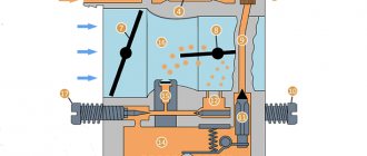
The physical principle of operation of the tachometer is based on counting the number of pulses that are recorded by the sensors, the order of their arrival, as well as the pauses between these pulses.
In this case, counting the number of pulses can be performed using various methods: forward, reverse and in both directions. The results obtained are usually transformed into the quantities we need. This value can be considered hours, minutes, seconds, meters, and the like.
The design of all tachometers allows the obtained values to be reset. The accuracy of these measurement results is quite conditional, about 500 rpm; the most accurate electronic tachometers measure with an error of up to 100 rpm.
Connecting the device yourself
Not everyone understands electronics, but it is still desirable to be able to connect a measuring device. This will not cause any difficulties, because there are only three wires. The first thing to do is take the wire from the tachometer into the engine compartment. The easiest way to do this is through the hole in the speedometer cable. Next you will need a piece of wire. It should be about one meter long, thin and tough. At one end, use electrical tape to secure the wire from the device. Try to work carefully. Carefully insert the other end of the wire into the holes in the cable and push. Connecting an electronic tachometer can be done as follows. The positive wire is connected to the ignition coil (pin B). Connect the signal wire to contact K of the same coil. Connect the minus to ground. Work as carefully as possible, the wires are very thin and very unreliable.
What is a tachometer anyway? A tachometer is a device used to measure the RPM (revolutions per minute) of any rotating body. Tachometers are made on the basis of contact or non-contact ones. Non-contact optical tachometers typically use a laser or infrared beam to monitor the rotation of any body. This is done by calculating the time taken for one rotation. In this material, taken from an English site, we will show you how to make a portable digital optical tachometer using Arduino Uno. Let's consider an extended version of the device with an LCD display and a modified code.
What types of car tachometers are there?
Car tachometers come in two types: digital and analog. A digital car tachometer consists of the following blocks:
The display of a digital automobile tachometer displays the results of measurements of shaft and engine revolutions. A digital tachometer is very useful when adjusting operations with electronic ignition units of a car engine, when accurately setting economizer thresholds, etc.
Analog car tachometers are more common and understandable to a larger number of car enthusiasts. It shows the measurement results using a moving arrow.
Typically an analog tachometer consists of
:
This tachometer works as follows. The signal from the crankshaft is transmitted through wires to a microcircuit, which determines the position of the arrow on a graduated dial.
It is best to have both types of tachometer in your car. So the digital one does an excellent job of adjusting the idle speed, checking the operation of the EPHH control unit (forced idle economizer) and checking the standard tachometer (since the digital tachometer has much higher accuracy). When driving a car, it is much more convenient to use a standard analog tachometer, since the human eye and brain analyzes analog information better and faster than its digital value, and better accuracy is not required at all while driving a vehicle.
In addition, tachometers are also classified according to the installation method. There are standard and remote car tachometers. The first is mounted directly into the car's dashboard. “It” is simpler and is used in most cars. The remote tachometer is designed for installation on the dashboard. They are used to give the car a more tuning appearance. The design of the remote tachometer has a leg for securing it to the dashboard.
Homemade digital tachometer car indicator
Below is a diagram of a quasi-analog electronic tachometer. The principle of its operation is as follows. Engine speed is displayed on a simplified linear LED scale. The digital tachometer scale consists of nine LEDs. Each of these roughly corresponds to 600 rpm of the engine. At idle, only the first LED lights up. The tachometer is adjusted by selecting resistance R6. Depending on it, you can set the indicators to the required number of cylinders. You can also change the division price.
The source of pulses for the correct operation of the digital tachometer can be a Hall sensor, which is present in the electronic ignition system, a shaft position sensor, and others. The main thing is that the sensor sends pulses to our circuit that change the resistance of resistor R1.
This circuit works as a simple frequency meter. Pulses that constantly come from the engine sensor are sent to the counting input of the K561IE8 decimal counter, and then to the LEDs. The circuit can be powered from the cigarette lighter or car radio connector.
Diode VD1 KD522 protects the circuit from incorrect connection of power polarity. The crankshaft speed sensor sends pulses to the base of transistor VT1. We select resistance R1 depending on the sensor (in the diagram, the resistance is selected for the Hall sensor in the contactless ignition system of a carburetor engine). From the output of VT1, the pulses go to the Schmitt trigger, made on elements D1.1-D1.2. It converts the pulses into the required rectangular shape. Capacitor C2 filters interference; paired with resistor R4, it forms a filter that cuts off high-frequency pulses. From Output D1.2, pulses are sent to the counter.
A multivibrator assembled on microcircuit elements D1.3 and D1.4 generates clock pulses with a frequency depending on R6. These pulses go to the C3-R7 chain, which forms a pulse to reset counter D2. Ultra-bright LEDs HL1-HL9 are connected directly to the outputs of the K561IE8 counter. Using R9 you can adjust the brightness of the display.
LEDs 1-4 on the printed circuit board are connected with a mounting wire.
Setting up the design begins with calculating the value of resistor R1 in accordance with the range of incoming pulses. Then we replace R6 with series-connected variable resistors of 1 Ohm and constant resistors of 10 kOhm. Next, we tighten the variable resistor to maximum resistance. Then we turn it so that only two LEDs light up when the engine is idling. We mark this position of the tuning resistor. Then we reduce the resistance so that only one LED lights up. Then we adjust the resistor to the middle position. Next, we measure the resulting resistance R8 with a multimeter.
DIY digital tachometer on AVR ATtiny2313, KR514ID2 and optocoupler
DIY digital tachometer on AVR ATtiny2313, KR514ID2 and optocoupler
Good afternoon. I present for your consideration a diagram of a simple digital tachometer on an AVR ATtiny2313
,
KR514ID2
, and an optocoupler designed by me.
Let me make a reservation right away: there are many similar schemes on the Internet. Each implementation has its own pros and cons. Perhaps my option will be more suitable for someone. I'll probably start with those. tasks. Task
: you need to make a digital tachometer to control the speed of the electric motor of the machine.
Introductory conditions
: There is a ready-made reference disk with 20 holes from a laser printer.
There are many optocouplers available from broken printers. Average (working) speeds are 4,000-5,000 rpm. The error of the displayed results should not exceed ± 100 revolutions. Limitation
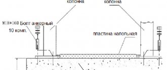
: the power supply for the control unit is 36V (the tachometer will be installed in the same housing with the control unit - more on this below).
A small lyrical digression.
This is my friend's machine. The machine is equipped with a PIK-8 electric motor, the speed of which is controlled according to a modified diagram found on the Internet. At the request of a friend, a simple tachometer for the machine was developed.
Initially, it was planned to use ATMega16 in the circuit, but after considering the conditions, it was decided to limit ourselves to ATtiny2313, operating from an internal (RC) oscillator at a frequency of 4 MHz.
General scheme
as follows:
As you can see, nothing complicated. To convert binary code into seven-segment, I used the KR514ID2 decoder, this gives three advantages at once.
- Firstly, it saves space in the ATtiny2313 memory by reducing the working code (since the procedure for software conversion of binary code to seven-segment is not included in the firmware as it is unnecessary).
- Secondly: reducing the load on the ATtiny2313 outputs, because the LEDs are “illuminated” by KR514ID2 (when the number 8 is displayed, the maximum consumption will be 20-30 mA (typical for one LED) * 7 = 140-210 mA, which is “a lot” for the ATtini2313 with its full nameplate maximum (loaded) consumption of 200 mA).
- Thirdly, the number of “busy” legs of the microcontroller has been reduced, which gives us the opportunity in the future (if necessary) to upgrade the circuit by adding new capabilities.
Assembling the device
implemented on a breadboard.
To do this, a circuit board from a non-working microwave oven lying in the bins was disassembled. The digital LED indicator, key transistors (VT1-VT4) and limiting resistors (R1 - R12) were taken as a kit and transferred to the new board. The entire device is assembled, if the necessary components are available, with smoke breaks in half an hour. Please note:
the KR514ID2 microcircuit has a positive power supply pin of 14 and a minus pin of 6 (marked in the diagram). Instead of KR514ID2, you can use any other binary code decoder into a seven-segment one powered by 5V. I took what was at hand. The “h” and “i” pins of the digital LED indicator are responsible for two points in the center between the numbers; they are not connected as unnecessary. After assembly and firmware, provided there are no installation errors, the device starts working immediately after switching on and does not require configuration.
If it is necessary to make changes to the tachometer firmware, an ISP connector is provided on the board.
In the diagram, pull-up resistor R12, rated 30 kOhm, was selected experimentally for a specific optocoupler. As practice shows, it may differ for different optocouplers, but the average value of 30 kOhm should ensure stable operation for most printer optocouplers. According to the ATtiny2313 documentation, the value of the internal pull-up resistor ranges from 20 to 50 kOhm, depending on the implementation of a specific batch of microcontrollers (page 177 of the ATtiny2313 passport), which is not entirely suitable. If anyone wants to repeat the circuit, they can first turn on the internal pull-up resistor, perhaps it will work for you, for your optocoupler and your MK. It didn't work for me for my set.
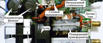
This is what a typical optocoupler from a printer looks like.
The optocoupler LED is powered through a 1K limiting resistor, which I placed directly on the board with the optocoupler. To filter voltage ripples, there are two capacitors in the circuit, an electrolytic one of 220 µF x 25V (which was on hand) and a ceramic one of 0.1 µF (the general circuit for connecting the microcontroller is taken from the ATtiny2313 data sheet).
To protect it from dust and dirt, the tachometer board is coated with a thick layer of automotive varnish.
Replacement of components.
You can use any four-digit LED indicator, either two double or four single. At worst, assemble the indicator on separate LEDs.
Instead of KR514ID2, you can use KR514ID1 (which contains current-limiting resistors inside), or 564ID5, K155PP5, K155ID9 (when the legs of one segment are connected in parallel), or any other binary to seven-segment converter (with appropriate changes in the connection of the microcircuit pins).
Provided the installation is correctly transferred to the ATMega8/ATMega16 MK, this firmware will work as on the ATtiny2313, but you need to correct the code (change the names of the constants) and recompile. Comparisons have not been made for other AVR MCUs.
Transistors VT1-VT4 - any low-current ones, operating in switch mode.
Principle of operation
is based on counting the number of pulses received from an optocoupler in one second and recalculating them to display the number of revolutions per minute. For this purpose, an internal counter Timer/Counter1 is used, operating in the mode of counting pulses arriving at input T1 (pin PD5 pin 9 MK). To ensure stable operation, software debounce mode is enabled. Seconds are counted by Timer/Counter0 plus one variable.
Calculation of revolutions
, which I would like to dwell on, occurs according to the following formula: M = (N / 20) *60, where M is the calculated revolutions per minute (60 seconds), N is the number of pulses from the optocoupler per second, 20 is the number of holes in the reference disk. In total, simplifying the formula we get: M = N*3. But! The ATtiny2313 microcontroller does not have a hardware multiplication function. Therefore, summation with offset was applied. For those who do not know the essence of the method: The number 3 can be expanded as 3 = 2+1 = 21 + 20. If we take our number N, shift it to the left by 1 byte and add another N shifted to the left by 0 byte - we get our number N multiplied by 3. In the firmware, the code on the AVR ASM for a two-byte multiplication operation looks like this:
Mul2bytes3: CLR LoCalcByte //clear the working registers CLR HiCalcByte mov LoCalcByte,LoInByte //load the values received from Timer/Counter1 mov HiCalcByte,HiInByte CLC //clear the carry bit ROL LoCalcByte //shift through the carry bit ROL HiCalcByte CLC ADD LoCalcByte,LoIn Byte/ / sum taking into account the carry bit ADC HiCalcByte,HiInByte ret
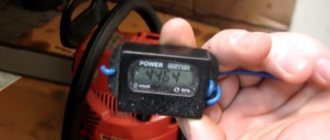
Functionality check and accuracy measurement
was carried out as follows. A cardboard disk with twenty holes was glued to the computer cooler fan. The cooler speed was monitored through the motherboard BIOS and compared with the tachometer readings. The deviation was about 20 revolutions at a frequency of 3200 revolutions/minute, which is 0.6%.
It is quite possible that the real discrepancy is less than 20 revolutions, because Motherboard measurements are rounded within 5 turns (based on personal observations for one specific board). The upper limit of measurement is 9,999 rpm. The lower limit of measurement, theoretically from ±10 revolutions, but was not measured in practice (one pulse from an optocoupler per second gives 3 revolutions per minute, which, taking into account the error, should theoretically correctly measure speeds from 4 revolutions per minute and above, but in practice this the indicator must be at least doubled).
I will separately dwell on the issue of nutrition.
The entire circuit is powered from a 5V source, the estimated consumption of the entire device does not exceed 300 mA. But, according to the terms of the technical specifications, the tachometer must be structurally located inside the engine speed control unit, and a constant voltage of 36V is supplied to the unit from LATR. In order not to pull a separate power wire, an LM317 is installed inside the unit in the nameplate mode, in the mode of reducing the power to 5V (with limiting resistor and zener diode to protect against accidental overvoltage). It would be more logical to use a PWM controller in step-down converter mode, like the MC34063, but in our city it’s problematic to buy such things, so we used what we could find.
Photos
tachometer boards and the finished device.
More photos
Unfortunately, it is not possible to take photos on the machine at the moment.
After the layout of the boards and the first test assembly, the box with the device went for painting.
Source,
on AVR ASM, AVR Studio4 project files and compiled .HEX file are located here: https://djkiridza.org.ua/ldd/taho-v029.zip. Mirror here: https://fileobmen.org.ua/DJ_Kiridza/taho-v029.zip
If your tachometer does not work
immediately after switching on, with known correct installation:
1) Check the operation of the microcontroller, make sure that it is powered by an internal generator. If the circuit is assembled correctly, four zeros should be displayed on the dial.
2) Check the level of pulses from the optocoupler, if necessary, select the value of resistor R12 or replace the optocoupler connection circuit. It is possible to reverse connect the optotransistor with a pull-up to minus, with the internal pull-up resistor MK turned on or not. It is also possible to use the transistor in the switching (inverting) mode of operation.
PS
at the request of the customer, the tachometer displays not one zero, but four in the absence of pulses from the optocoupler.
P.P.S.
The tachometer turned out to be very sensitive to changes in engine speed. Minor voltage ripples cause a deviation in the rotation speed, which is immediately displayed on the tachometer screen. In the future, I plan to make processing to round the displayed results within ±50 revolutions, if the customer needs it.
Do-it-yourself tachometer - production and practical application
Let's start with definitions. What is a tachometer in a car? This is a device that records the crankshaft speed in a car.
Of course, its use is not limited to vehicles. Determining the number of revolutions per minute is necessary when working with various mechanisms:
- airplane turbine
- ship propulsion shaft
- power station generators
- high precision milling and lathes
- drilling rigs
- electricity and water metering devices.
In addition, instruments for measuring rotation speed are used in research work. Any tachometer consists of two parts:
- The rotation sensor takes readings from the shaft - the object of measurement
- The signaling device either sends a command to the control circuit of the mechanism, or simply displays data on a pointer device (digital display).
Another homemade tachometer
In order to measure the number of revolutions, as we already know, counting the pulses of the breaker or the voltage from the spark plugs is used. The frequency of these pulses is linearly related to the motor speed. You can also try to organize an inductive coupling with such a circuit, which will be demonstrated in this device. The basis for this option is a single-vibrator labeled LM 555.
The principle of operation of the tachometer is quite simple
There are several types of design:
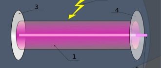
Pulse electrical circuit
A mark emitting any field is installed on the shaft whose frequency is being measured.
Most often this is a small magnet. A reading device – a sensor – is placed next to the shaft. Pulses corresponding to the shaft rotation speed are formed on it.
An electronic circuit receives signals and outputs them to a display device. Instead of a magnet-sensor pair, a photo and an LED are sometimes used.
Then a disk with a hole is installed on the shaft, and reading occurs using flashes of light.
The advantage of the scheme is perfect accuracy. In fact, this is a digital device that works without errors. In addition, this scheme does not take power away from the engine.
Disadvantage: Requires power supply. This excludes the use of the device in purely mechanical units.
Video of a homemade tachometer working
Share useful diagrams
Such a power supply can power fairly powerful low-frequency amplifiers or adapt the unit to an ordinary 12-volt amplifier from the TDA series. In addition, the power supply can be supplemented with a voltage regulator and used as a switching laboratory power supply.
| DEVICES BASED ON ELECTRIC LIGHTERS
|
| POWERFUL POWER SUPPLY FOR UMZCH |
To power high-power audio amplifiers - from 0.5 kW and above, in order to reduce the size of the power supply, special switching power supplies are required. Let's take a look at the schematic diagram of such a device.
Automatic electronic timer for supplying water to the pool - circuit on a microcontroller for self-assembly.
How to assemble a table lamp based on a fluorescent tube and electronic ballast from a non-working energy saver.
How to make a tachometer with your own hands?
If it is impossible or expensive to restore a factory device, you can do it yourself. The same problem is often solved by owners of auto-moto vehicles that do not have a tachometer in their design.
Video of a simple tachometer assembled with your own hands from a voltmeter, a motor from an old printer and a diode bridge.
Installing the sensor on the crankshaft is quite difficult, and the balancing may be disrupted. It’s easier to use any pulley that rotates synchronously with the motor.
If there is a hole, install a photo pair and connect it to the electronic tachometer.
The circuit can be purchased as a ready-made KIT kit (on Chinese electronics websites), or assembled using an available element base.
There are ways to connect a homemade tachometer to the ignition system. Each pulse applied to the high-voltage spark plug coil corresponds to one revolution of the crankshaft.
We remove the signal and feed it to the tachometer circuit. If the standard device on your car has failed, or you want to duplicate it on a separate display, it is possible to connect the tachometer to the generator. This is the most common pulse delivery scheme.
We take the signal for the revolution counter from the “W” connector of the generator. The connection is standard, this is how many models of factory tachometers work.
If you have doubts about the correctness, look at the electrical diagram of your car, you need to find the conductor from the generator to the device.
Bottom line Making a homemade tachometer is quite simple if you have basic electrical engineering skills. If you have a soldering iron and a ready-made circuit, it’s a matter of a couple of days off.
An element base for every taste: from a simple pulse counter to a controller assembled on ARDUINO. The main thing is to understand how the standard device in your car works.
An example of a homemade tachometer from a computer mouse. All the details are in the video material.
What is it for? If the standard tachometer is broken, the answer is obvious. If everything is in order with your dashboard, you can add a stylish element to the interior of the car. The digital display is easier to read, and the LED indication will add clarity.
Tachometer for motorcycles
How to install an electronic tachometer on a motorcycle? Here, motor vehicle owners have a choice: either purchase ready-made equipment or make it themselves. Let's assume that there is a motorcycle, there is a device for monitoring revolutions. But how to connect an electronic tachometer? For these purposes, the TX-193 device from the six is best suited for installation on domestic brands of motorcycles.
If the motorcycle is not domestic and there is still the same electronic tachometer, the connection diagram will change slightly. In this case, power will have to be supplied through the ignition switch. There are special contacts there for these purposes. If the motorcycle does not have a starter, then the battery should be connected to the output of the rectifier. And from the battery you can supply power directly to the tachometer through a switch. If you don't have a rectifier, you need to buy one. If you don't have a battery, you can install one. The simplest option is a power source from a UPS or an old flashlight. If you connect the measuring device directly to the generator coil, then it will burn out. To avoid this, you can ask your neighbor, a radio amateur, to make a voltage regulator using thyristors.
If the engine has three cylinders, then signals from two coils are input here. There are also technical possibilities for installing a tachometer on six-cylinder motorcycles, but for this you already need to purchase branded equipment.
Simple speed metronome
Tachometer comes from two Greek words: “tacho” meaning “speed” and “metronome” meaning “to measure”. It works on the principle of a generator and determines the voltage corresponding to the speed of the shaft. It is also known as a revolution counter. Principle of operation:
- induction;
- electromagnetic;
- electronic;
- optic.
Historically, the first mechanical tachometer was developed based on the measurement of centrifugal force. In 1817 they were used to measure the speed of traction machines, but after 1840 they were used primarily to measure the speed of vehicles. A digital tachometer is an optical sensor designed to determine the angular velocity of a rotating element. Areas of use:
- Cars, planes, tractors, trains, light rail vehicles and their repair.
- Laser tools.
- Medical use. A hematachometer is a device placed in an artery or vein that measures the speed of blood movement through a rotating turbine. The indications are used to diagnose circulatory problems such as thrombophlebitis.
- Analog audio recording that measures the speed of an audio tape.
- Estimation of traffic speed and volume.
Types of modern tachometers
An important parameter that is taken into account when choosing a device is the operating speed range. It sets the limit of the measurement that the device is capable of monitoring. Another parameter is accuracy, which is specified in units such as ± RPM. Sensor technology used: contact, photoelectric, inductive and Hall effect.
In a contact type device, it comes into contact with a rotating part. A photoelectric device uses light rays, either visible or infrared, to measure speed. The frequency of the break, which is used to calculate speed. Inductive instruments use magnetic elements to induce magnetic fields and an activation frequency to measure speed. Design features:
Display configurations include analog visual indicators, digital or graphic video displays. User interfaces and control types include analog front or digital panels and computer programmable interfaces. Modern tachometers are equipped with software for running on a PC. Many have network or communication interfaces. Available electrical outputs:
- analog voltage;
- analog current;
- analog modulated frequency;
- switch or alarm;
- LED screen.
Microelectric Voltage Generated Machine
The tachometer generator converts the shaft rotation indicator into an electrical signal. Its operation uses the properties of the angular velocity of the rotor, the excitation flow, which is proportional to the generated EMF. Most modern tachogenerators are the permanent magnet type. These devices use a rotating joint, one end of which is connected to the machine shaft, inducing an electromotive force (voltage) proportional to the speed of the shaft. The armature contacts are connected to the voltmeter circuit, converting the voltage into a speed value.
These tachometers are distinguished by their accuracy, maximum permissible performance and operating temperature. Used as sensors in various automotive and electromechanical computer devices. Operate in AC or DC networks.
Operating principle of a car meter
The tachometer is used to check the performance of the engine and helps the auto mechanic understand its condition to optimize operation within acceptable parameters. The operating principle of a car electronic tachometer is simple. The ignition system triggers a voltage pulse in the electromechanical part of the tachometer, which responds to the average voltage of the pulses in proportion to the engine speed. The signal is transmitted by a double shielded cable to the indicator. Tachometers are temperature compensated to process measurements in the range of -20 to + 70 C ambient.
It allows the driver to select appropriate throttle and gear settings while driving, as long-term use at high speeds causes insufficient lubrication, affecting the engine, creating overheating and leading to unnecessary wear and tear and machine failure.
Checking engine speed
While operating a car, you need to know how to check the tachometer at home. Most cars are equipped with a speedometer, pressure gauge, coolant temperature sensor and tachometer. They are installed differently depending on the make and model of the car. Sequencing:
- Check the tachometer before driving, carefully inspect the sensors. The dial usually shows single or double digit numbers, which are limited by the red stripe of the permitted operating limit.
- Start the car. Press the brake pedal with your right foot and turn on the ignition key. The tachometer reading should rise before stopping at the engine idle speed.
- Press the gas pedal and pay attention to the behavior of the tachometer.
- Monitor the readings while driving in each gear and when switching to the next.
- Avoid excessive motor overload. The red line on the scale represents the highest number of revolutions the engine can safely handle.
- If you need to further measure the vehicle's RPM to help diagnose the problem, use a handheld tachometer that measures the RPM while running.
Schematic parts list
- Microcircuit - Arduino
- Resistors – 33k, 270 ohm, 10k potentiometer
- LED element - blue
- IR LED and Photodiode
- 16 x 2 LCD screen
- 74HC595 shift register
Here, instead of a slot sensor, an optical one is used - reflection of the beam. This way they don't have to worry about the thickness of the rotor, the number of blades won't change the reading, and it can read the drum revolutions - which the slot sensor cannot.
So first of all you will need an IR emitting LED and a photodiode for the sensor. How to assemble it is shown in step-by-step instructions. Click on the photo to enlarge the size.
- 1. First you need to sand the LED and photodiode to make them flat.
- 2. Then fold the strip of paper sheet as shown in the picture. Make two such structures so that the LED and photodiode fit tightly into it. Connect them together with glue and paint them black.
- 3. Insert LED and photodiode.
- 4. Glue them together with superglue and solder the wires.
Resistor values may vary depending on which photodiode you are using. The potentiometer helps to reduce or increase the sensitivity of the sensor. Solder the sensor wires as shown in the figure.
The tachometer circuit uses a 74HC595 8-bit shift register with a 16x2 LCD display. Make a small hole in the housing to fix the LED indicator.
Solder a 270 ohm resistor onto the LED and insert it into pin 12 of the Arduino. The sensor is inserted into a cubic tube to give additional mechanical strength.
That's it, the device is ready for calibration and programming. You can download the program from this link.
DIY electronic tachometer
With the wide possibilities of the electronics market, it is not difficult to make a tachometer circuit at home using a multimeter. Moreover, the results obtained in such circuits are accurate in assessing the overall operating condition of the system being measured.
Circuit diagram using IC 555:
- The pulse is taken out from the scooter's spark plug and fed to the end of R6.
- The transistor responds to impulses in accordance with triggers.
- The transistor activates monostability with each incoming pulse.
- The monostable remains on for a certain moment, and when triggered, generates an average on-time output that is directly proportional to the average startup speed.
- The capacitor and resistor at the output of the IC combine the result so that it is directly read by a 10V voltmeter.
- R3 is adjusted so that the output generates an accurate interpretation of the RPM feed rate.
The above adjustment is made using a conventional tachometer. Parts for manufacturing are widely available and can be purchased at any radio supply store. List of parts for the homemade version:
- R1 = 4K7.
- R2 = 47E.
- R3 = 100 KB, may be variable.
- R4 = 3K3.
- R5 = 10K.
- R6 = 470 K.
- R7 = 1K.
- R8 = 10K.
- R9 = 100K.
- C1 = 47n.
- C2 = 100n.
- C3 = 100n.
- C4 = 33uF / 25V.
- T1 = BC547.
- IC1 = 555.
- M1 = 10V FSD meter.
- D2 = 1N4148.
- C5 with any value between 3.3uF and 4.7uF.
Before you make a tachometer with your own hands, you need to complete the installation documentation. A simple circuit designed using readily available elements with a rubberized MOC7811 opto-isolator module and two seven-segment displays measures disk speed in RPS. This circuit calculates RPS from 00 to 99; if larger values are needed, another decade counter is added.
The circuit diagram contains IC555, MOC 7811, IC CD4081, IC CD4069 and IC 4033 and a seven-segment LTS 543 display unit. On the first timer IC 555, configured as a monostable multivibrator, it generates a clock pulse when switch S2 is pressed, green LED 1 indicates the detection time .
MOC 7811 IC2 contains an IR transmitter and a photodiode to create varying logic levels, depending on the blocking or interrupting IR beam. Logic gate N1 includes the Johnson detector counter (CD 4033) and controls the LTS 543 seven-segment display. There are two decimal counters and two seven-segment displays to display RPS from 00 to 99.
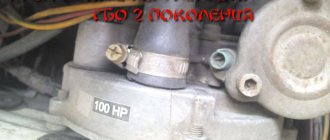
Using this scheme, you can make a tachometer for a chainsaw with your own hands with a rotating breaker. One interruption of the infrared beam will be taken as one count, and the total rotation count is RPS, multiply 60 by RPS to find Revolution Per Minute (RPM).
Electronic tachometer circuit on Arduino
To assemble the device, you will naturally need an Arduino microcontroller. If it is not there, then any other controller with similar characteristics will do, but then you will need to additionally assemble the programmer. Also for this circuit you need resistors 33 kOhm, 270 Ohm, 10 kOhm in the form of a potentiometer. You can also purchase a blue LED, an infrared LED and a photodiode. Next, find the DSV display and the shift register chip labeled 74NS595. It uses an optical sensor and the principle of reflecting rays. With this system, you don't have to worry about how thick the rotor should be, and the number of rotor blades won't change the performance. The sensor will be able to accurately read the revolutions.
Car tachometer diagram
The main task of a tachometer in a car is to help select the correct gear, which has a positive effect on the life of the engine. Most cars already have an analog tachometer and when the needle approaches the red mark, you need to shift into a higher gear.
In addition, car owners use it for adjustment work, both at idle and to control the engine speed while driving.
The physical principle of operation of the tachometer is based on counting the number of pulses that are recorded by the sensors, the order of their arrival, as well as the pauses between these pulses.
In this case, counting the number of pulses can be performed using various methods: forward, reverse and in both directions. The results obtained are usually transformed into the quantities we need. This value can be considered hours, minutes, seconds, meters, and the like.
The design of all tachometers allows the obtained values to be reset. The accuracy of these measurement results is quite conditional, about 500 rpm; the most accurate electronic tachometers measure with an error of up to 100 rpm.
What types of car tachometers are there?
Car tachometers come in two types: digital and analog. A digital car tachometer consists of the following blocks:
The display of a digital automobile tachometer displays the results of measurements of shaft and engine revolutions. A digital tachometer is very useful when adjusting operations with electronic ignition units of a car engine, when accurately setting economizer thresholds, etc.
Analog car tachometers are more common and understandable to a larger number of car enthusiasts. It shows the measurement results using a moving arrow.
Typically an analog tachometer consists of
:
This tachometer works as follows. The signal from the crankshaft is transmitted through wires to a microcircuit, which determines the position of the arrow on a graduated dial.
It is best to have both types of tachometer in your car. So the digital one does an excellent job of adjusting the idle speed, checking the operation of the EPHH control unit (forced idle economizer) and checking the standard tachometer (since the digital tachometer has much higher accuracy). When driving a car, it is much more convenient to use a standard analog tachometer, since the human eye and brain analyzes analog information better and faster than its digital value, and better accuracy is not required at all while driving a vehicle.
In addition, tachometers are also classified according to the installation method. There are standard and remote car tachometers. The first is mounted directly into the car's dashboard. “It” is simpler and is used in most cars. The remote tachometer is designed for installation on the dashboard. They are used to give the car a more tuning appearance. The design of the remote tachometer has a leg for securing it to the dashboard.