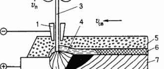
Welding in shielding gases can be carried out with consumable and non-consumable electrodes. When welding (surfacing) with a consumable electrode (Fig. 2.9, a), an electric arc burns between the electrode wire fed into the welding zone (into the arc) and the product. The arc melts the electrode wire and the base metal. The molten metal of the electrode and the base metal mix to form a bath. As the weld pool metal cools, it hardens, forming a weld. Welding with a non-consumable electrode can be performed with a direct or indirect arc.
In direct arc welding, an electric arc burns between a non-consumable carbon or tungsten electrode and the workpiece. Moving along the edges of the connection, the arc melts them. As the arc moves, the molten metal solidifies and forms a seam connecting the edges of the product. When welding with a non-consumable electrode with an indirect arc, an electric arc burns between non-consumable carbon or tungsten electrodes. The product is not included in the electrical circuit. Moving along the edges of the connection, the arc melts them. As the arc moves, the molten metal solidifies and forms a seam connecting the edges of the product.
Rice. 1. Scheme of surfacing in protective gases: a - with a consumable electrode; b - non-consumable electrode with a direct arc; c - non-consumable electrode with an indirect arc: 1 - gas nozzle; 2 - melting electrode wire; 3 - arc; 4 - shielding gas; 5 - welded product; 6 - non-consumable electrode; 7 - filler rod; 8 - deposited metal.
Welding with a non-consumable electrode with a direct arc can also be carried out with the supply of filler material to the welding zone. One of the main conditions for obtaining a high-quality weld when welding (surfacing) in shielding gases is reliable protection of the arc zone and molten metal with shielding gas, preventing air from entering the welding zone.
In repair practice, semi-automatic and automatic welding (surfacing) with consumable and non-consumable electrodes has found application.
Restoration of parts by surfacing and welding in a carbon dioxide environment. The most common method is welding (surfacing) in a carbon dioxide environment with a consumable electrode. The advantage of this method is the high efficiency of the process. The surfacing process in a carbon dioxide environment is 1.2...1.5 times more economical than the submerged arc welding process, and the productivity is 25...30% higher.
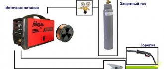
When surfacing in a carbon dioxide environment, the weld is well formed, the deposited metal is dense, and the heat-affected zone is small. Due to these advantages, the method is in most cases used for welding thin sheet metal and for surfacing parts made of carbon and low-alloy steels 10 mm. Carbon dioxide is supplied according to the scheme cylinder - heater - dryer - reduction gear - flow meter - burner (surfacing head). Heating and drying of carbon dioxide is necessary in order to eliminate possible blockage of holes in the reducer by ice, which can form from gas expansion, and also to prevent porosity.
To reduce the gas pressure supplied to the arc zone from 5...5.5 to 0.05...0.2 MPa, a reduction reducer of type RK-53B (GOST 5313-59) with high and low pressure gauges is used. The gas flow rate is determined using the scale of the low-pressure manometer, calibrated in l/min.
For semi-automatic welding in a carbon dioxide environment, semi-automatic machines A-547U, A-547R, A-537, A-1035, A-929, PDPG-500, PDG-301, PDG-501, etc. are widely used.
IES named after E. O. Paton developed the semi-automatic A-1631 pulling type with a pneumatic drive. The machine is compact and user-friendly in design.
Of the surfacing machines, they usually use the A-580M, produced for submerged arc surfacing, having made a corresponding gas burner and mouthpiece for it. In this case, the PSO-500 current source is replaced with a welding converter or rectifier with a rigid external characteristic. With similar equipment and the necessary gas equipment for surfacing in CO2, surfacing heads OKS-6569 and OKS-1252A (GMVK-2), equipped with a PSU-500 current source, can also be used.
Installations for automatic surfacing in a carbon dioxide environment (as well as installations for welding and surfacing under a layer of flux) are mounted on converted lathes that provide surfacing speeds in the range of 20 ... 120 m/h, on the support of which a surfacing apparatus is installed. The part to be restored is fixed in the machine chuck. A mouthpiece is connected to the surfacing apparatus to supply carbon dioxide to the surfacing zone.
Noteworthy is the UD-209 installation for arc surfacing of external cylindrical surfaces of parts with self-shielding flux-cored wire PP-AN-122 0 2.0...3.2 mm with electrode oscillations, solid wire Sv-08 GS 0 1.2...2.0 mm in CO2 environment and submerged arc in a spiral, as well as other types of wires with a diameter within the specified limits with a deposition rate of 12... 18 g/Ah.
Welding (surfacing) in carbon dioxide, as a rule, is carried out using direct current with reverse polarity with a rigid external characteristic of the current source.
Atomic oxygen has high chemical activity and is capable of oxidizing all elements that make up the base metal wire. The release of oxide gas leads to the formation of pores. This explains the oxidizing effect of carbon dioxide and the need to use deoxidizing agents when welding. Deoxidizers (silicon, manganese, titanium), by binding oxygen, prevent the formation of carbon monoxide. The presence of more than 0.2% silicon and more than 0.4% manganese in the weld metal prevents the formation of pores.
Since with this method there are no fluxes or coatings, the problem of deoxidation and alloying of the weld pool can only be solved by selecting wire of the appropriate chemical composition. In accordance with this, wire grades Sv-10KhG2S, Sv-12GS, Sv-08G2S, Sv-YUGS, Sv-08GS, Np-ZOKHGSA, Sv-18KhGSA with a diameter of 0.5 to 1.6 mm are used for welding and surfacing. Along with solid electrode wire, flux-cored wire of the PP-18T, PP-R9T, PP-4Kh2V8T, PP-AN4, PP-AN5, PP-AN122, PP-Kh12VFT brands is also used. For welding parts made of carbon steel sheets with a thickness of 2...5 mm, the most successful results were obtained when using wires of the Sv-08G2S and Sv-YUGSMT grades.
For surfacing worn parts of machines made of low- and medium-carbon steel (with the exception of parts operating in an abrasive environment), the best wire is Np-ZOKHGSA grade.
The welding (surfacing) mode in a carbon dioxide environment includes the welding current value, arc voltage, electrode wire diameter, welding speed and electrode stickout value.
The magnitude of the welding current and the diameter of the electrode wire are selected depending on the thickness of the metal being welded.
As the voltage increases, the length of the arc increases, and the path of droplet transfer of metal through the arc gap increases accordingly, which contributes to the intensity of its oxidation, spattering and burning out of manganese and silicon. Low arc voltage causes excessive weld reinforcement and high undercuts. The magnitude of the welding current depends on the feed speed of the electrode wire.
The hardness of the deposited metal is achieved through the use of appropriate welding wire. Thus, the hardness of parts made of steel 40, 40X and 45 deposited with wire Sv-10GSMT and Sv-08G2S is HB 230...290 (2300...2900 MPa), and after hardening and low tempering - 40.5...42.5 HRC3. Surfacing of parts made from the same steels with Sv-10X13 wire gives a hardness without heat treatment of 49.5...51.5 HRC3, and with Np-2X14 wire - 51.5...53 HRC3.
Semi-automatic welding is performed with the torch tilted forward or backward at an angle of 5... 15°. It is recommended to weld butt and fillet vertical welds on thin metal from top to bottom. The introduction of semi-automatic welding in a carbon dioxide environment during the repair of bodies and cabins significantly improves the quality of welds and reduces the amount of manual welding work by 60%. Welding in a carbon dioxide environment can significantly reduce the consumption of scarce materials.
When restoring thin-walled sheet structures, the efficiency of the process can be increased through the use of arc power sources with reduced dynamic characteristics (ZP-4/ZO, EP-7.5/30 converters, VDG-301 rectifiers), sequential inclusion of inductance 0, 2...0.3 mg, as well as introducing argon into carbon dioxide. At the same time, as experiments have shown, the type of droplet transfer of electrode metal changes, its spattering is noticeably reduced (from 12...15% when welding in CO2 to 5% when welding in CO2 + 50% Аg), short circuits of the arc gap when welding at low temperatures are eliminated currents, which contributes to better seam formation and improvement of welding technological parameters.
Automatic surfacing of critical parts with high hardness of working surfaces (shaft, clutch, crank axle) should be carried out using Np-ZOKHGSA or Sv-18KhGSA wire 0 1.2...1.8 mm, followed by heat treatment (normalization, hardening with heating with high-frequency currents) , and parts with a hardness of 200...250 HB (2000...2500 MPa) - with wire Sv-08G2S, Sv-YUGS.
Surfacing modes: arc voltage 18…22 V, welding current 120…180 A, surfacing speed 25…50 m/h, step
surfacing 2.5...8.5 mm/rev, electrode extension 15...20 mm, electrode wire feed speed 90...180 m/h, carbon dioxide consumption 0.48...0.72 m3/h.
To restore the internal holes of the front axle housings of MTZ-type tractors, balancers and drive wheels of tractors of traction class 3 using electric arc surfacing in a protective gas environment, an OKS-11239-GOSNIT surfacing machine with a capacity of 28 holes (155 mm in diameter and 25 mm in length) per shift was developed. The diameters of the restored holes are 45… 250 mm.
A number of enterprises use automatic surfacing in a carbon dioxide environment with directed cooling to restore machine parts. The essence of the method is that a coolant (5% solution of soda ash in water) is applied to the metal deposited in a carbon dioxide environment (when its temperature is equal to or higher than the quenching temperature), which ensures the hardening of the applied layer.
By changing the location of the coolant supply depending on the chemical composition of the electrode wire, it is possible to regulate the hardness of the deposited metal within 27...51.5 HRC3 (without additional heat treatment). When choosing the optimal parameters for the surfacing mode of parts (for wire with a diameter of 1 ... 1.2 mm), it is recommended to use the modes indicated in table. 2.9.
Subject to these conditions, using electrode wires Sv-08G2S, Sv-18KhGSA, Np-ZOKHGSA, the deposited metal is obtained without pores, cavities and cracks. For multi-electrode surfacing, the semi-automatic A-765 can be used. Using this method, it is possible to apply coatings to parts with a diameter of 15...50 mm of a wide range of machine parts (camshafts, gearbox shafts, expansion knuckles, axle tubes and other parts). The economic effect from the implementation of one surfacing installation averages 10...15 thousand rubles, or 25...30 tons of metal per year.
It has been experimentally proven that it is possible to obtain a high-quality coating by surfacing in a CO2 environment with high-carbon steel wires of grades steel 70 and U8A with surface high-temperature thermomechanical treatment (HTTMT) in one technological operation, which allows avoiding subsequent
strengthening the deposited layer by hardening with heating by high-frequency currents, obtaining dense metal without pores and cracks, and also expands the possibilities of using this method of restoring parts. Under optimal conditions for the PVTMT process (deformation force by rollers - 4.0 kN, the distance at which the roller is located, and the location of the coolant supply from the electrode axis - 10 and 20 mm, respectively), a significant increase in the tensile strength was established (by 10...11.5 %), wear resistance of the metal coating (by 28...36%) and the coefficient of relative elongation (15%) in comparison with the initial state with high-quality fusion of the deposited metal with the base one. The results of laboratory studies are confirmed by operational tests of the steering knuckle axles of the T-16 and DT-20 tractors.
The Maloyaroslavets branch of GOSNITI and TsOKTB have developed a surfacing machine OKS-11232-GOSNITI for the restoration of “shaft” type parts, including crank axles, gearbox shafts, transmissions, clutches, rolling axles, as well as automatic wide-layer arc surfacing with Sv-08GS wire thickness 1 .5...3 mm with hardness up to HRC340 or more (with subsequent heat treatment) in a carbon dioxide environment.
The largest diameter and length of the deposited shafts are 100 and 800 mm, respectively. Power source - rectifier VDG-301. Overall dimensions 2230Х X 1070×1360 mm. The economic effect from the introduction of a surfacing machine is, according to GOSNITI, about 5.0 thousand rubles.
A promising direction for further improving the performance characteristics of parts restored by surfacing in a carbon dioxide environment is chemical-thermal treatment. Thus, the wear resistance of products deposited with Sv-08GSA and Sv-18KhGSA wires and strengthened by nitrocarburization is more than twice as high as the wear resistance of samples made of steel 45, hardened by heating with high-frequency currents, and their endurance limit is significantly higher than the endurance limit of samples strengthened using other methods. technologies.
Bench and operational tests of low-resource interfaces (satellite axle - satellite of the MTZ tractor) with parts restored by surfacing in a CO2 environment followed by hardening by nitrocarburization showed that the service life of the satellite axles reaches more than 90% of the service life of serially manufactured products.
In body production, where semi-automatic welding in a carbon dioxide environment replaces manual methods of arc and gas welding, annual savings from each installation average 1.5 thousand rubles. by reducing the cost of consumable filler materials and gases and increasing productivity. In some cases, when the use of welding in a carbon dioxide environment simplifies the technology of preparing a product for welding, reduces the cost of cleaning seams, and improves the quality of welding, the economic effect can be significant. As a rule, the use of this progressive method improves quality, reduces warping, and improves the appearance of the connection.
In the future, when repairing cars, the use of welding in a carbon dioxide environment should significantly expand to make butt joints of thin-sheet steel on the outer panels of bodies and cabins of tractors and cars, which will allow, with low labor intensity of cleaning seams, to avoid the use of lead-tin solders and other expensive materials.
Automatic welding in carbon dioxide with large-diameter wire (including flux-cored wires) at forced modes reaching several hundred meters per hour should become widespread for welding products such as wheels, rear axles, car frames, etc.
Restoration of aluminum parts by welding in argon. Welding in an argon environment is most appropriate for the restoration of parts made of aluminum alloys. The increased tendency of these alloys to form pores is the main difficulty in obtaining high-quality welded joints.
Porosity in welded joints. The main reason for porosity in aluminum alloys is the presence of hydrogen in them, and the reason for the saturation of the weld metal with atomic hydrogen is moisture adsorbed by the oxide film on the surface of the welding wire and the edges being welded. Hydrogen released from the base metal by diffusion influences the formation of gas porosity in the weld and shrinkage porosity in the heat-affected zone. In addition to the latter, nitrogen may enter the weld pool (does not have a significant effect on the creation of pores, since it forms metal nitride, which turns into slag) and oxygen, which combines with aluminum to form the oxide AI2O3 and, probably, does not have a significant effect on the formation of porosity in weld metal. The formation of the latter depends on the cleanliness of the metal surface, the quality of preparation for welding of aluminum and filler material, the purity of protective gases, including argon, the composition of the protective atmosphere, welding conditions, etc.
To reduce porosity in the weld metal, the following is recommended: before welding, the oxide film A1203 should be carefully removed from the base and filler materials and the remaining etching products (for example NaOH) should be removed by washing; during work, ensure reliable gas protection of the seam from the atmosphere, use filler wire that is as free from other impurities as possible, and of the largest possible diameter, and reduce the time spent in the air of the welded edges and filler material prepared for work by immediately welding the parts; choose the right shielding gases, in the absence of argon, use a mixture of Ar - He (65...75% Not by volume) and use preheating of products before welding (the latter increases the presence of the metal in a liquid state and, therefore, facilitates the removal of soluble gases from it); introduce ultrasonic vibrations into the liquid and crystallizing metal of the weld pool, which facilitate the release of hydrogen from molten aluminum. However, the use of ultrasound significantly increases the cost of the technology for restoring parts and complicates working conditions.
Oxide films. A refractory oxide film A1203 covers the surface of the aluminum alloy and has a melting point of R050°C. while the base metal melts at 650...670°C. The film reliably protects the alloy from further oxidation up to temperatures of 680...720 °C (with increasing temperature, the thickness of the oxide layer increases, and the protective properties of the film deteriorate). The refractory oxide film interferes with the fusion of the product and, when it gets into the seam, it becomes a non-metallic inclusion, which, having a higher density than the base metal, sinks to the bottom of the weld pool and in most cases remains in the seam, contributing to destruction or the appearance of leaks in it.
A1203 film has increased hygroscopicity and low plasticity. To destroy and remove it, special fluxes or mechanical action are required. The mechanism of action of the components of fluxes and coatings on aluminum oxide consists of wetting the film, loosening it and washing it into slag. This process is facilitated by the release of gases resulting from the interaction of fluxes with liquid metal.
The quality of welding can also be significantly improved by mechanical removal of the oxide film (using metal scrapers and brushes) from the surface of the molten metal.
Parts made of aluminum alloys are often welded by gas welding with an oxygen-acetylene neutral flame using AF-4A flux (28% sodium chloride, 50% potassium chloride, 14% lithium chloride and 8% sodium fluoride), which facilitates the complete removal of oxide films during the welding process. Arc welding with special electrodes OZA-1 and OZA-2, respectively, is also used for welding pure aluminum and aluminum-silicon alloys (such as silumin).
In this case, chemical destruction of the film occurs due to the introduction of chloride and fluoride salts of sodium, potassium and lithium into the coating of the electrodes. The chemical method of film removal also occurs in automatic submerged arc welding AN-4A with a semi-closed arc on serial machines.
It should be noted that, in addition to special techniques for removing the oxide film, an electric arc of direct polarity, burning in argon, helium or their mixtures, has an effective effect. Its effect is that positive ions moving at high speed bombard the surface of the weld pool, destroy the relatively thin oxide film and remove it by “spraying”. In the case of large thickness of aluminum oxides, it is necessary to use special mechanical or chemical methods.
Restoration by welding in argon. The high thermal conductivity of aluminum alloys requires the use of powerful heat sources for welding. In addition to arc power circuits based on standard welding transformers (STE-24, STE-34 with a built-in choke type STN-500, STN-700, TSD-500, TSD-1000 and complete with reactive coil STN-TSD), the repair industry is widely used special installations such as UDAR-500, UDG-ZS1, UDG-500 or UDG-500M are used, designed for argon-arc welding of aluminum and its alloys using alternating current. The installation consists of power supplies (transformer with choke), control cabinet, water-cooled burners and gas cylinder with reducer. To regulate the welding current and ensure the receipt of a falling external characteristic and a current change curve in the circuit with an accelerated transition through the zero value, which helps to increase the stability of the arc, a saturation choke is used.
Rice. 2. Diagram of a station for welding with a non-consumable electrode using alternating current: 1 - welding transformer; 2 - throttle; 3 - oscillator; 4 — ballast rheostat; 5 - AC ammeter; 6 - DC ammeter; 7 - voltmeter; 8 — burner (electrode holder); 9 — rotameter; 10 - gearbox; 11 — low pressure gauge; 12 — gas cylinder; 13 - welder's table.
Rice. 3. Scheme of welding parts in an argon environment: 1 – part to be restored; 2 - deposited metal; 3 - filler rod; 4 - tungsten electrode; 5 - burner.
To excite the arc without shorting the electrode, an oscillator is used, which turns off during operation.
To melt the base metal and filler wire, non-consumable electrodes made of lanthanum tungsten BJI-10 VP-24-5-62 (with an admixture of 0.9...1.1 lanthanum) or thoriated electrodes VT-15TU VP-2-529-527 (with containing 1.5...2 thorium oxide) with a diameter of 1...5 mm. Pure argon grade A according to GOST 10157-62 is used as a shielding gas. An electric arc burns between the surface of the part being restored and a tungsten electrode in an argon environment.
During welding, the angle between the filler wire and the electrode should be about 90°, and the arc should be maintained at a distance of 1.5...3.0 mm from the surface of the weld pool.
The optimal distance from the torch nozzle to the welding seam should be 10...12 mm.
The arc is excited and the electrode is heated away from the welded area on the graphite plate.
6...8 g of tungsten (0.04...0.07 g/m) is consumed per 1 kg of deposited metal. Welding is carried out using AK filler material containing up to 5% silicon. Before welding, the wire must be cleaned of oil and oxide film by etching in an 8...10% solution of orthophosphoric acid, and then washed in hot water.
The filler wire can also be cleaned using the following technology: etching in a 5% caustic soda solution at a temperature of 60...65 °C for 2...3 minutes; washing in hot (45...50 °C) water, and then in cold running water; treatment in a 15...30% solution of nitric acid at a temperature of 60...65° C for 2...3 minutes; repeated rinsing in hot and cold water; drying at a temperature not lower than 60 ° C until moisture is completely removed.
The welding site is prepared depending on the nature of the defect. It is also advisable to clean parts for welding by chemical treatment using the above technology, and it is advisable to process small-sized parts entirely, and submit large-sized items for restoration completely degreased and chemically treated up to 100 mm from the welding edge joint.
If it is impossible to chemically treat the latter, it is allowed to clean the edges of the part with stainless steel wire brushes (wire 0 0.2 mm) with preliminary and subsequent wiping of the surface to be cleaned with acetone. When multi-pass welding, before applying each subsequent bead, it is recommended to thoroughly clean the seam and groove surfaces with wire brushes and wipe them with degreasing liquids. The surfaces of parts with a wall thickness of up to 3 mm must be cleaned of contamination by 25...30 mm on both sides of the crack to a metallic shine without chamfering the edges.
For parts with wall thicknesses from 3...6 to 10 mm, chamfering on the edges of the crack is carried out on one side, and with wall thicknesses of 10...20 mm - on both sides at an angle of 70...90° with cleaning of the surface in the crack zone on both sides 15...20 mm and blunting of the top of the cone with radii of 3...3.5 and 5...6 mm, respectively. The hole in the wall of the product is repaired by welding a patch from an AMC sheet with a thickness of 1.5...2 mm. In this case, the edges of the patch should fit tightly to the wall and overlap the boundaries of the hole by 4...6 mm. Argon-arc welding modes are given in table. 2.10.
In all cases of welding parts made of aluminum alloys, it is recommended: 1. Preheating of the parts to be restored to a temperature of 250...300 ° C (to prevent warping of parts due to heating during welding and the occurrence of cracks, calmer crystallization of the liquid metal). 2. Subsequent (after welding) low-temperature annealing at 300...350 °C (to relieve internal stresses and improve the structure of the weld). 3. Use of aluminum alloy containing 5...6% silicon as a filler material (for argon-arc and gas welding).
The filler material must be homogeneous with the material being welded and can be obtained by remelting the corresponding rejected parts made of aluminum alloys (block heads, covers, etc.).
By welding aluminum and its alloys in an argon environment, repair companies successfully restore clutch housings, cylinder blocks with cracks in the valve box cavity and in the walls of the cooling jackets (with access to the head contact cavity), cylinder heads, and clutch housing covers of the SMD-14 engine.
The accumulated experience indicates the feasibility and effectiveness of using argon-arc welding for the restoration of parts made of aluminum alloys.
5.3. Welding and surfacing of parts in shielding gases
When welding and surfacing in a shielding gas environment, gas is supplied to the arc combustion zone under low pressure, which displaces air from this zone and protects the weld pool from oxygen and nitrogen in the air.
Depending on the gas used, welding is divided into welding in active (CO2, H2, O2, etc.) and inert (He, Ar, Ar+He, etc.) gases. Welding (surfacing) can be carried out with both consumable and non-consumable electrodes.
The most widely used methods for restoring rolling stock parts are welding and surfacing in a carbon dioxide (CO2) environment - welding with a consumable electrode (wire) with carbon dioxide protecting the weld pool from air. This method is the cheapest when welding carbon and low-alloy steels. Therefore, in terms of production volume, it occupies one of the first places among mechanized fusion welding methods.
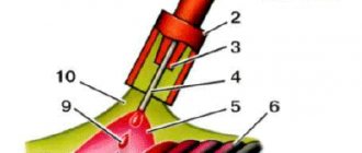
When welding (surfacing) in a carbon dioxide environment ( Fig. 5.3 ) flows out from the torch nozzle 2 4 entering the arc combustion zone , displacing air from the weld pool.
Rice. 5.3. Arc welding in shielding gas with a consumable electrode: 1 – electric arc; 2 – gas nozzle; 3– feed rollers; 4 – electrode wire; 5 – current-carrying mouthpiece; 6 – shielding gas
However, during the welding process, carbon dioxide dissociates under the influence of high temperatures:
2СО2<=>2СО+О2. Therefore, welding does not take place in pure carbon dioxide, but in a mixture of CO2, CO and O2 gases. In this case, almost complete protection of the molten metal from air nitrogen is provided, but the oxidizing nature of the gas mixture remains almost the same as it would be when welding with bare wire without protection from the air atmosphere.
Therefore, when welding and surfacing in a CO2 environment, it is necessary to take measures to deoxidize the deposited metal.
This problem is solved by using welding wires with a diameter of 0.8–2 mm, which contain deoxidizing elements. Most often these are silicon (0.6–1.0%) and manganese (1–2%). In the presence of such components, deoxidation of iron oxides occurs according to the reactions 2 FeO + Si ―> SiO2 + 2Fe and FeO + Mn ―> MnO + Fe.
The oxides of silicon and manganese formed during the deoxidation process float to the surface of the weld pool and are removed after crystallization of the metal.
The most widely used electrode wires when welding in a CO2 environment are Sv-08GS, SV-10GS, Sv-08G2S, Sv-18KhGS, etc. *
In addition to solid wires, flux-cored wires such as PP-AN4, PP-AN5, PP-AN8, PP-3X2V8T, etc. are often used.**
If the welding wire does not contain a sufficient amount of deoxidizers, then welding is accompanied by large spattering of the metal, the presence of pores in it after crystallization, and a high probability of cracks forming in the deposited layer. Welding in a CO2 environment has a number of advantages : a minimal zone of structural changes in the metal with a high degree of arc concentration and current density; a greater degree of protection of the weld pool from the influence of the external environment; significant performance; the ability to monitor the formation of a seam; the ability to weld metal of various thicknesses (from tenths to tens of millimeters), weld in various spatial positions, mechanize, automate the technological process; slight sensitivity to rust and other base metal contaminants.
However, when choosing this method of welding and surfacing, it is necessary to take into account its disadvantages : strong spattering of metal at a current of more than 500 A, which requires constant protection and cleaning of the torch nozzle; intense radiation from an open powerful arc, requiring welder protection; the need to cool the burner at high currents; welding is carried out almost exclusively on direct current; presence of special wire.
Technical characteristics of semi-automatic machines for welding in shielding gases are given in Table 7 of the Appendix.
* GOST 2246-70 Steel welding wire
** GOST 26271-84 Flux-cored wire for welding low-carbon and low-alloy steels. GOST 26101-84 Flux-cored surfacing wire.