When laying an insulated pipeline in a trench and then backfilling it, the insulating coating may be damaged, and during the operation of the pipeline it gradually ages (loses its dielectric properties, water resistance, adhesion). Therefore, for all installation methods, except above-ground, pipelines are subject to comprehensive protection against corrosion with protective coatings and electrochemical protection (ECP) means, regardless of the corrosive activity of the soil.
ECP means include cathodic, sacrificial and electrical drainage protection.
Protection against soil corrosion is carried out by cathodic polarization of pipelines. If cathodic polarization is carried out using an external direct current source, then such protection is called cathodic, but if polarization is carried out by connecting the protected pipeline to a metal that has a more negative potential, then such protection is called sacrificial.
Cathodic protection
The schematic diagram of cathodic protection is shown in the figure.
The source of direct current is the cathodic protection station 3, where, with the help of rectifiers, the alternating current from the along-route power line 1, entering through the transformer point 2, is converted into direct current.
The negative pole of the source is connected to the protected pipeline 6 using connecting wire 4, and the positive pole is connected to the anode grounding 5. When the current source is turned on, the electrical circuit is closed through the soil electrolyte.
Definition of electrochemical protection
Electrochemical protection of pipelines from corrosion is a process carried out under the influence of a constant electric field on a protected object made of metals or alloys. Since alternating current is usually available for operation, special rectifiers are used to convert it to direct current.
In the case of cathodic protection of pipelines, the protected object acquires a negative potential by applying an electromagnetic field to it, that is, it becomes a cathode.
Accordingly, if a section of pipe protected from corrosion becomes a “minus”, then the grounding connected to it becomes a “plus” (i.e. an anode).
Anti-corrosion protection using this method is impossible without the presence of an electrolytic medium with good conductivity. In the case of underground pipelines, its function is performed by the soil. The contact of the electrodes is ensured by the use of elements made of metals and alloys that conduct electric current well.
During the process, a constant potential difference arises between the electrolyte medium (in this case, soil) and the element protected from corrosion, the value of which is controlled using high-voltage voltmeters.
Schematic diagram of cathodic protection
1 - power lines; 2 - transformer point; 3 — cathodic protection station; 4 - connecting wire; 5 - anodic grounding; 6 - pipeline
The operating principle of cathodic protection is as follows. Under the influence of the applied electric field of the source, the movement of half-free valence electrons begins in the direction “anode grounding - current source - protected structure”. Losing electrons, the anodic grounding metal atoms pass in the form of ion atoms into the electrolyte solution, i.e. the anodic grounding is destroyed. Ion atoms undergo hydration and are removed into the depth of the solution. At the protected structure, due to the operation of the direct current source, an excess of free electrons is observed, i.e. conditions are created for the occurrence of oxygen and hydrogen depolarization reactions characteristic of the cathode.
Underground communications of oil depots are protected by cathode installations with various types of anodic grounding. The required protective current strength of the cathode installation is determined by the formula
Jdr=j3·F3·K0
where j3 is the required value of the protective current density; F3 is the total contact surface of underground structures with the ground; K0 is the coefficient of exposure of communications, the value of which is determined depending on the transition resistance of the insulating coating Rnep and the electrical resistivity of the soil rg according to the graph shown in the figure below.
The required value of the protective current density is selected depending on the characteristics of the soil at the oil depot site in accordance with the table below.
Features of ECP of pipelines
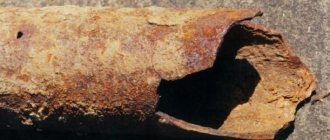
The main reason for pipeline failure (partial depressurization or complete destruction of individual elements) is metal corrosion. As a result of the formation of rust on the surface of the product, micro-tears, cavities and cracks appear on its surface, gradually leading to system failure. This problem is especially relevant for pipes that run underground and are constantly in contact with groundwater.
The operating principle of cathodic protection of pipelines against corrosion involves the creation of an electrical potential difference and is implemented in the two ways described above.
After carrying out measurements on the ground, it was found that the required potential at which any corrosion process slows down is –0.85 V; for pipeline elements located under the earth layer, its natural value is –0.55 V.
In order to significantly slow down the processes of destruction of materials, it is necessary to reduce the cathode potential of the protected part by 0.3 V. If this is achieved, the corrosion rate of steel elements will not exceed 10 μm/year.
One of the most serious threats to metal products is stray currents, that is, electrical discharges penetrating into the ground due to the operation of grounding power lines (power lines), lightning rods, or movement on train rails. It is impossible to determine at what time and where they will appear.
The destructive effect of stray currents on steel structural elements appears when these parts have a positive electrical potential relative to the electrolytic medium (in the case of pipelines, soil). The cathodic technique imparts a negative potential to the protected product, as a result of which the risk of corrosion due to this factor is eliminated.
The optimal way to provide the circuit with electric current is to use an external energy source: it guarantees the supply of voltage sufficient to “break through” the soil resistivity.
Typically, overhead power transmission lines with powers of 6 and 10 kW act as such a source. If there are no power lines in the pipeline area, mobile generators operating on gas and diesel fuel should be used.
Tread protection
The principle of operation of the tread protection is similar to the operation of a galvanic cell.
Two electrodes: pipeline 1 and protector 2, made of a more electronegative metal than steel, are lowered into the soil electrolyte and connected by wire 3. Since the protector material is more electronegative, under the influence of a potential difference, a directed movement of electrons occurs from the protector to the pipeline along the conductor 3. At the same time, the ion atoms of the protector material go into solution, which leads to its destruction. The current strength is controlled using control and measuring column 4.
Dependence of protective current density on soil characteristics
| Soil type | rp ohmm | A, A/m2 |
| Wet clay soil: | ||
| — pH >8 | 15 | 0,033 |
| pH = 6-8 | 15 | 0,160 |
| - mixed with sand | 15 | 0,187 |
| Wet peat (pH <8) | 15 | 0,160 |
| Moistened sand | 50 | 0,170 |
| Dry clay soil | 100 | 0,008 |
Schematic diagram of tread protection
1 - pipeline; 2 — protector; 3 - connecting wire; 4 - control and measuring column
Thus, metal destruction still occurs. But not the pipeline, but the protector.
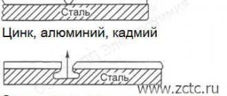
Theoretically, to protect steel structures from corrosion, all metals located in the electrochemical voltage series to the left of iron can be used, since they are more electronegative. In practice, protectors are made only from materials that meet the following requirements:
- the potential difference between the tread material and iron (steel) should be as large as possible;
- the current obtained by electrochemical dissolution of a unit of mass of the protector (current output) must be maximum;
- the ratio of the tread mass used to create protective current to the total loss of tread mass (utilization factor) should be the greatest.
These requirements are best met by alloys based on magnesium, zinc and aluminum.
Tread protection is carried out with concentrated and extended protectors. In the first case, the electrical resistivity of the soil should be no more than 50 Ohm-m, in the second - no more than 500 Ohm-m.
Electrical drainage protection of pipelines
A method of protecting pipelines from destruction by stray currents, providing for their removal (drainage) from the protected structure to a structure that is a source of stray currents or special grounding, is called electrical drainage protection.
Direct, polarized and reinforced drainage are used.
Electrochemical protection (ECP)
Anti-corrosion protection products
- Corrosion of underground pipelines and protection against it
- Cathodic protection installations
- Drainage protection installations
- Galvanic protection installations
- Installations with extended or distributed anodes.
1. Corrosion of underground pipelines and protection against it
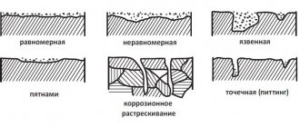
Corrosion of underground pipelines is one of the main reasons for their depressurization due to the formation of cavities, cracks and ruptures. Corrosion of metals, i.e. their oxidation is the transition of metal atoms from a free state to a chemically bound, ionic state. In this case, the metal atoms lose their electrons, and the oxidizing agents accept them. On an underground pipeline, due to the heterogeneity of the pipe metal and due to the heterogeneity of the soil (both in physical properties and chemical composition), areas with different electrode potentials appear, which causes the formation of galvanic corrosion. The most important types of corrosion are: superficial (solid over the entire surface), local in the form of shells, pitting, crevice and fatigue corrosion cracking. The last two types of corrosion pose the greatest danger to underground pipelines. Surface corrosion only rarely causes damage, while pitting corrosion causes the greatest number of damage. The corrosion situation in which a metal pipeline is located in the ground depends on a large number of factors related to soil and climatic conditions, route characteristics, and operating conditions. These factors include:
- soil moisture,
- chemical composition of the soil,
- acidity of the ground electrolyte,
- soil structure,
- temperature of transported gas
The most powerful negative manifestation of stray currents in the ground, caused by electrified DC rail transport, is electrocorrosive destruction of pipelines. The intensity of stray currents and their impact on underground pipelines depends on factors such as:
- rail-to-ground contact resistance;
- longitudinal resistance of running rails;
- distance between traction substations;
- current consumption by electric trains;
- number and cross-section of suction lines;
- electrical resistivity of soil;
- distance and location of the pipeline relative to the path;
- transition and longitudinal resistance of the pipeline.
It should be noted that stray currents in cathode zones have a protective effect on the structure, therefore, in such places, cathodic protection of the pipeline can be carried out without large capital costs.
Methods for protecting underground metal pipelines from corrosion are divided into passive and active.
The passive method of corrosion protection involves creating an impenetrable barrier between the metal of the pipeline and the surrounding soil. This is achieved by applying special protective coatings to the pipe (bitumen, coal tar pitch, polymer tapes, epoxy resins, etc.).
In practice, it is not possible to achieve complete continuity of the insulating coating. Different types of coating have different diffusion permeability and therefore provide different insulation of the pipe from the environment. During construction and operation, cracks, scuffs, dents and other defects appear in the insulating coating. The most dangerous are through damage to the protective coating, where, in practice, ground corrosion occurs.
Since the passive method does not allow complete protection of the pipeline from corrosion, active protection is simultaneously applied, associated with the control of electrochemical processes occurring at the boundary of the pipe metal and the ground electrolyte. This type of protection is called comprehensive protection.
The active method of corrosion protection is carried out by cathodic polarization and is based on reducing the rate of dissolution of the metal as its corrosion potential shifts to an area of more negative values than the natural potential. It was experimentally established that the value of the cathodic protection potential of steel is minus 0.85 Volts relative to the copper sulfate reference electrode. Since the natural potential of steel in the ground is approximately -0.55...-0.6 Volts, to implement cathodic protection it is necessary to shift the corrosion potential by 0.25...0.30 Volts in the negative direction.
By applying an electric current between the metal surface of the pipe and the ground, it is necessary to achieve a reduction in the potential in defective areas of the pipe insulation to a value below the protective potential criterion of -0.9 V. As a result, the corrosion rate is significantly reduced.
2. Cathodic protection installations Cathodic protection of pipelines can be carried out using two methods:
- the use of magnesium sacrificial protector anodes (galvanic method);
- using external direct current sources, the minus of which is connected to the pipe, and the plus to anode grounding (electrical method).
The galvanic method is based on the fact that different metals in the electrolyte have different electrode potentials. If you form a galvanic couple from two metals and place them in an electrolyte, the metal with a more negative potential will become the anode and will be destroyed, thereby protecting the metal with a less negative potential. In practice, protectors made of magnesium, aluminum and zinc alloys are used as sacrificial galvanic anodes.
The use of cathodic protection using protectors is effective only in low-resistivity soils (up to 50 Ohm-m). In high-resistivity soils, this method does not provide the necessary protection. Cathodic protection by external current sources is more complex and labor-intensive, but it depends little on the resistivity of the soil and has an unlimited energy resource.
As a rule, converters of various designs powered from an alternating current network are used as direct current sources. The converters allow you to regulate the protective current over a wide range, ensuring pipeline protection in any conditions.
0.4 overhead lines are used as power sources for cathodic protection installations; 6; 10 kV. The protective current applied to the pipeline from the converter and creating a “pipe-ground” potential difference is distributed unevenly along the length of the pipeline. Therefore, the maximum absolute value of this difference is located at the point of connection of the current source (drainage point). As you move away from this point, the pipe-ground potential difference decreases. Excessively increasing the potential difference negatively affects the adhesion of the coating and can cause hydrogenation of the pipe metal, which can cause hydrogen cracking. Cathodic protection is one of the methods of combating metal corrosion in aggressive chemical environments. It is based on transferring a metal from an active state to a passive state and maintaining this state using an external cathode current. To protect underground pipelines from corrosion, cathodic protection stations (CPS) are built along their route. The VCS includes a direct current source (protective installation), anode grounding, a control and measuring point, connecting wires and cables. Depending on the conditions, protective installations can be powered from an alternating current network 0.4; 6 or 10 kV or from autonomous sources. When protecting multi-line pipelines laid in one corridor, several installations can be installed and several anode groundings can be constructed. However, taking into account that during interruptions in the operation of the protection system, due to the difference in natural potentials of the pipes connected by a blind jumper, powerful galvanic couples are formed, leading to intense corrosion, the connection of the pipes to the installation must be carried out through special joint protection units. These blocks not only disconnect the pipes from each other, but also allow you to set the optimal potential on each pipe. Converters powered by a 220 V industrial frequency network are mainly used as direct current sources for cathodic protection in VSCs. The output voltage of the converter is adjusted manually, by switching the taps of the transformer winding, or automatically, using controlled valves (thyristors). If cathodic protection installations operate under time-varying conditions, which may be caused by the influence of stray currents, changes in soil resistivity or other factors, then it is advisable to provide converters with automatic control of the output voltage. Automatic regulation can be carried out according to the potential of the protected structure (potentiostat converters) or according to the protection current (galvanostat converters).
3. Drainage protection installations
Electric drainage is the simplest type of active protection that does not require a current source, since the pipeline is electrically connected to the traction rails of the source of stray currents. The source of the protective current is the pipeline-rail potential difference, which arises as a result of the operation of electrified railway transport and the presence of a field of stray currents. The flow of drainage current creates the required potential shift in the underground pipeline. As a rule, fuses are used as a protective device, but maximum load circuit breakers with reset are also used, that is, they restore the drainage circuit after the current dangerous for the installation elements subsides. As a polarized element, valve blocks assembled from several avalanche silicon diodes connected in parallel are used. The current in the drainage circuit is regulated by changing the resistance in this circuit by switching active resistors. If the use of polarized electric drains is ineffective, then reinforced (forced) electric drains are used, which are a cathodic protection installation, the rails of an electrified railway are used as an anode grounding electrode. The current of forced drainage operating in cathodic protection mode should not exceed 100A, and its use should not lead to the appearance of positive rail potentials relative to the ground in order to prevent corrosion of rails and rail fastenings, as well as structures attached to them.
Electrical drainage protection can be connected to the rail network directly only to the middle points of track choke transformers through two to a third choke points. More frequent connections are allowed if a special protective device is included in the drainage circuit. A choke can be used as such a device, the total input resistance of which to the signal current of the main railway signaling system with a frequency of 50 Hz is at least 5 Ohms.
4. Galvanic protection installations
Galvanic protection installations (protector installations) are used for cathodic protection of underground metal structures in cases where the use of installations powered by external current sources is not economically feasible: the absence of power lines, the short length of the facility, etc.
Typically, protector installations are used for cathodic protection of the following underground structures:
- tanks and pipelines that do not have electrical contacts with adjacent extended communications;
- individual sections of pipelines that are not provided with a sufficient level of protection from converters;
- sections of pipelines electrically isolated from the main line by insulating connections;
- steel protective casings (cartridges), underground tanks and containers, steel supports and piles and other concentrated objects;
- the linear part of the main pipelines under construction before the commissioning of permanent cathodic protection installations.
Sufficiently effective protection with protective installations can be carried out in soils with a specific electrical resistivity of no more than 50 Ohms.
5. Installations with extended or distributed anodes.
As already noted, when using a traditional cathodic protection scheme, the distribution of the protective potential along the pipeline is uneven. The uneven distribution of the protective potential leads to both excessive protection near the drainage point, i.e. to unproductive energy consumption and to a reduction in the protective zone of the installation. This disadvantage can be avoided by using a circuit with extended or distributed anodes. The ECP technological scheme with distributed anodes makes it possible to increase the length of the protective zone compared to the cathodic protection scheme with concentrated anodes, and also ensures a more uniform distribution of the protective potential. When using the ZHZ technological scheme with distributed anodes, various layouts of anode grounding can be used. The simplest is the scheme with anode groundings evenly installed along the gas pipeline. Adjustment of the protective potential is carried out by changing the anodic grounding current using an adjusting resistance or any other device that ensures a change in the current within the required limits. In the case of grounding from several grounding electrodes, the protective current can be adjusted by changing the number of connected grounding electrodes. In general, the ground electrodes closest to the converter should have a higher contact resistance. Protective protection Electrochemical protection using protectors is based on the fact that due to the potential difference between the protector and the protected metal in an electrolyte environment, the metal is restored and the protector body dissolves. Since the bulk of metal structures in the world are made of iron, metals with a more negative electrode potential than iron can be used as a protector. There are three of them - zinc, aluminum and magnesium. The main difference between magnesium protectors is the largest potential difference between magnesium and steel, which has a beneficial effect on the radius of protective action, which ranges from 10 to 200 m, which allows the use of fewer magnesium protectors than zinc and aluminum. In addition, magnesium and magnesium alloys, unlike zinc and aluminum, do not have polarization, accompanied by a decrease in current output. This feature determines the main use of magnesium protectors for the protection of underground pipelines in soils with high resistivity