What are copy rings? What are they for and how to use them?
These questions are asked not only by beginners, but sometimes also by craftsmen with experience working with milling tools. What is it?
A copying ring is a device that allows you to process a part with high precision using a template. The second name for the copy ring is copy sleeve. It is mainly used to repeat many of the same type of processing of parts, for example, inserting door fittings: card and hidden hinges, locks, latches and strike plates for them. The ring is attached to the instrument using screws or latches provided in the design.
A copying ring is not always supplied with the router, and if it is, it may not be the right size for your tasks. You can purchase copying rings of the required diameter from a milling tool manufacturer, a template tool manufacturer, or order it from a turner.
In addition to copy rings, cutters with bearings can be used to work with the template. The bearing can be located above the cutter and at its end. The disadvantage of such cutters is the inability to dive to a greater depth to process the part. The depth of processing is limited by the height of the end of the template located relative to the part.
For a high-quality result, you need to take into account several nuances. Select the required dimensions of the ring and cutter, since the dimensions of the milling directly depend on this. The difference between the size of the diameters of the ring and the cutter is laid down during the manufacture of the template. Select a router that has no backlash under lateral and longitudinal loads. The outer diameter of the ring must be centered relative to the diameter of the cutting part of the cutter.
I talk in more detail about copy rings and their use in my video on this topic. To view click here.
Source: yamasterwood.com
What is it and what is it for?
The copying sleeve is a ring that slides along the edge of the template. As a result, the cutter exactly follows the specified contour and does not intersect the marking lines. It is impossible to cut a workpiece smoothly by guiding the tool manually, much less make several completely identical parts.
The copy sleeve consists of a ring and a flange. The axis of symmetry of the device coincides with the axis of rotation of the spindle. The flange is made according to the size of the hole in the supporting plane of the router, and is attached to it. When pressure is applied to the housing with the motor, the working part of the tool is lowered along the guides, perpendicular to the supporting sole.
The cutter ends up below the sole and cuts into the workpiece. The copying ring rests its side surface against the end of the template, preventing the tool from going beyond its boundaries. Using a stencil, you can cut out a design of any complexity onto a part. It is enough to go along the contour with a cutter, then clean the entire area of the understatement.
How to make it yourself?
The strength and wear resistance of the metal of the copy ring determines how long the device will last. Power tool manufacturers make their bushings from tool steel. To connect the ring and flange, special welding equipment is used.
At home, you can make less durable, but cheaper devices for the router. To do this you will need a benchtop lathe.
Only a highly qualified specialist can weld together parts of such thickness. For amateurs, it is enough to place the flange on the glue and rivet the thin end of the ring.
How to use such a device for a router?
The stencil is applied to the workpiece according to the markings and fixed. A hole is made with a drill. A cutter is inserted into it and the contour is processed.
In everyday life, groove milling using a copy sleeve is most often used when installing doors. Craftsmen cut out grooves for handles and locks on site with high precision, and make lowerings for canopy slats.
In carpentry workshops, decorative furniture elements are cut out using a template. Using shaped cutters, a carpenter produces batches of parts with complex patterns. The copying sleeve makes it accessible and simple to select grooves and recesses of any configuration. It is enough to make the template correctly and adjust the processing depth.
Source
What is a copy sleeve used for?
It helps to confidently guide the cutting elements of the router along a complex trajectory, maintaining the distance between the cutter blade and the edge of the template. As a rule, it is used in conjunction with various templates and rules that should be followed along the edge of the part. The outer edges of this instrument necessarily extend beyond the sole of the instrument.
Copy bushings for router
Installation should be done using two mounting bolts. They are mounted in the threaded holes on the base of the router that are available there. There is a separate class of bushings; they are height adjustable. They must be used where a tight fit of the sleeve itself to the template or rule is required over an extremely large area. They are fixed with a clamping screw or screwed in from the bottom of the plate. The manufacturer makes the diameters of the guide surface of the bushing different in size and does this in order to be able to work with cutters of different diameters, as well as create combinations of cutters with bushings. The length of the segment limited by the edge of the template and the cut line is determined by the difference in the diameters of the guide plane of the copy sleeve and the cylinder. When working with a template, you should take this parameter into account. The length of the segment from the sleeve to the cutter is approximately 3–4 mm. This is done in order to ensure the free exit of chips arising during the work process. To protect the workpiece, it is important that the flange and heads of the bushing fastening screws do not extend beyond the plane of the milling machine base. The bushing flange must be flat and fit tightly into the groove intended for it. Before installing the bushing, this groove must be cleared of chips and resin. The thickness of the template plays an important role in the work process. At the same time, it should be such a thickness that the sleeve does not rest against the workpiece. This is necessary so that the protrusion does not spoil the part. With its help, you can mill liners, recesses, and also cut out various decorative elements.
Copy ring for Fiolent router
The copy ring is a round plate with a protruding shoulder that slides around the template when working. In this way, the required trajectory of movement of the cutting element of the milling cutter is ensured. The ring is attached with screws to the base of the milling machine. During operation, the ring protects the template from the cutting effects of the cutter teeth. The copy ring is characterized by such properties as strength, reliability, durability, and wear resistance.
On the Russian market you can purchase these Fiolent products at a low price - about 10–20 USD. e. Fiolent products are budget-friendly and designed for the mass segment of consumers.
Basic techniques and life hacks for a hand router
Let's start with the fact that there are different types of manual milling cutters: edge cutters, rod cutters, rodless cutters, and simply specialized ones, for example, for cutting in door locks or repairing window frames. Let us dwell in detail on the most universal and, as a result, the most popular - rod ones. Such a tool consists of two parts: the upper part, which includes the motor, handles, collet clamp, vertical position clamps, and the lower part - with rods, support sole and turret stop. Machines of this type are distinguished by the fact that they allow immersion into the material being processed to the required (within the limits of capabilities) depth. Using examples of specific operations, we will consider important design features of modern devices of this type.
WE'RE PREPARED FOR WORK
Let's start with the basics - preparing for work. Depending on the material and task, a cutter is selected. You will find numerous reviews and advice on choosing cutters on the Internet and on forums. General recommendations for choosing cutters are as follows. For soft wood, plywood, MDF and aluminum, an attachment with high-speed steel (HSS) knives is used; the more expensive, precise and resistant one with carbide blades (HM) is not prohibited. In other cases - chipboard, hardwood, composite compositions such as artificial marble and the like - the use of NM is mandatory. As mentioned, one of the important features of carbide blades is precision: they leave a cleaner surface.
Depending on the diameter of the cutter and the material, the rotation speed is set. Since the adjustment wheel is usually marked in conventional units, you will have to use instructions that indicate when to set what. Generally speaking, setting the speed is a very responsible procedure. Firstly, large-diameter equipment may not withstand too high a speed, and secondly, it is important to choose the right mode. If the frequency is too high, there is a risk of “burning” the workpiece; if the frequency is too low, productivity drops and the quality of processing deteriorates.
Having decided on the speed and type of cutter, install the equipment. The risks on the shank will help you do this correctly - you need to focus on them. If you need to deviate from the prescription (or it simply wasn’t there), use a simple rule - fix 2/3-3/4 of the total length of the shank.
When buying “consumables”, it is important to remember that the clamp diameters are different. Typically, collets are available for 6, 8 or 12 mm shanks. If you can’t find the right size equipment, don’t worry – just change the collet. It is an insert located inside the hollow drive shaft and secured with a nut.
So, it's time to clamp the cutter. This is done with an open-end wrench, having previously secured the shaft. Simpler models will need a second key, mid-level tools have a locking button, but the most convenient latch is also equipped with a “ratchet” - in this case you won’t even have to grab it.
1. The cutter is clamped into the collet using an open-end wrench and a shaft locking mechanism. If the latter is not provided, you will need a second key. In this case, the installation is extremely simplified - the stopper is equipped with a switchable (unscrewing/wrapping) “ratchet”. The cutter is clamped, guided by the markings on it or based on the general rule (2/3-3/4 of the length of the shank).
2. The “head” of the tool is lowered until the cutter stops against the surface, after which it is convenient to fix it. Next, based on the reach of the cutting equipment and the desired depth of processing, select the lowest of the suitable “legs” of the turret stop. This allows you to pass workpieces in several stages without repeating precise adjustments. Often the position of each “leg” can be adjusted within small limits. The support rod is lowered onto the selected “stand”, having first released its clamp. Without fixing it, but only pressing it with a finger, they move the movable pointer along it, ensuring that it coincides with the zero of the measuring ruler.
3. The bar is raised until the pointer coincides with the required division of the measuring scale and clamped with a clamp.
4. If the operation requires precision, a good router allows you to adjust the set depth value. It is changed without loosening (so as not to knock down) the fixation of the support rod, but by rotating the adjustment wheel. This can be done in advance, having achieved an exact match between the marks of the pointer and the scale, or after a trial pass.
5. When the “head” is lowered, the cutter will enter the workpiece to the depth set on the calibrated scale.
MILLING DEPTH
The next setup step is setting the immersion depth. It is set by a vertical stop, which can have several stages of adjustment. The most popular is the position of the stop itself. Having rested it on the lowest of the legs of the “revolver” (if possible), loosen the clamps of the stop (usually a wing clamp is implemented) and the “head” itself and lower it until the cutter touches the surface. Note that it is not at all necessary to use a workpiece; it is better to perform this operation on the plane of the workbench, without the risk of damaging the part.
Now you need to fix the movable stop or simply hold it with one hand, and with the other set the movable pointer (it “moves” up and down) opposite the zero division of the measuring scale, thereby calibrating the ruler. That's it, she's ready to go.
By moving the stop and following the pointer, adjust the depth and tighten the screw of the movable stop. If the router is “simple”, then the adjustment is complete. Otherwise, the immersion depth is adjusted more accurately. The position of the movable (already fixed) stop is changed with an accuracy of tenths of a millimeter by turning the adjusting wheel. It has latches (“clicks” along the divisions) or simply rotates tightly. The first option is better, since the installation will not fail during operation. It is good when such adjustment is implemented within wide limits, and it is very convenient when it can be done directly during operation.
MILLING
Without going into the specifics of the operations and skipping the “Positioning the machine on a plane” point, we’ll tell you how to get started. Having established the maximum immersion depth, it is, if necessary, “divided” into several steps - the turret stop is designed for this. In the vast majority of cases, it has three adjustable legs. Sometimes there are more of them, for example eight, which, however, is not considered a sign of a high-class instrument, but rather speaks of originality. Without touching the leg on which the immersion depth was set, set the steps higher. The logic of action here is the same as in the case of revolutions - too large a cross-section of the passage at once will lead to slow movement and “burning” of the material, too small - to a loss of productivity. Optimum is important. By turning the drum and moving from a high stop to a low one, they move along the workpiece to the desired depth.
Starting each pass, proceed like this. Turn on the motor, lower the cutter (into the material or outside the workpiece, depending on the situation) and secure the “head” with a stopper. If there are several passes or there is no confidence that the operation was successful, it is repeated. It is important to remember that you need to move along the workpiece in a strictly defined direction - the material is towards the rotating knives. It is impossible to drive the router “backwards”, as this will lead to defects. The direction of movement is usually indicated by an arrow on the sole; it is the same for all models.
A few words about the rod mechanism for raising/lowering the “head”. It is important to pay attention to the manufacturing class. Movement should be smooth and easy, without distortions or backlashes. It’s good when the stopper acts on two rods - with this arrangement, the rigidity and accuracy of fixation is higher.
We hope that the reader has already understood that the main thing in a router is adjustments. They are required to ensure accuracy (this, by the way, largely depends on the rigidity of the structural elements) and convenience. But if you delve into the intricacies of performing operations, it becomes clear that something else is no less important - the system. By it we mean a manual machine with devices for positioning it on a plane (without the latter, the router will be of little use, at least its versatility will suffer greatly). Let’s start the story about the “milling machine + guide vane” system with the simplest cases.
CUTTER WITH SUPPORT BEARING
The most elementary and compact device that sets the position of the machine is the cutter itself, if it is supplemented with a miniature ball bearing. It is located under or above the cutting knives and, accordingly, rests on the upper or lower edge of the edge. With the help of such equipment, shaped edges are obtained or grooves are cut for a connection, edging, seal, etc.
The advantages of the method include the ease of preparatory operations (you only need to adjust the vertical position) and the ability to accurately process rounded and curved edges (a typical example is a tabletop). The disadvantages follow from the advantages - it will not be possible to make a curve straight.
PARALLEL STOP
All of the above can be done with a regular cutter without a support bearing (it’s cheaper) if you use a copy ring or a rip fence. Let's start with emphasis. All milling cutters without exception are equipped with it, but this does not mean that it is the same for everyone. In the simplest case, the stop is a bent metal plate on two steel rods with a cutout in the center. Guides with locks are provided for them in the sole of the router. To ensure rigidity, they are made long (the entire slab) or short, but double - two spaced apart for each rod. Fixation occurs at a minimum of two points (one on each side), and a maximum of four. In the “primitive” version, such a stop has significant disadvantages - low rigidity of the stamped structure, difficulty in fine-tuning the position, restrictions on the diameter of the cutter used (it must fit in the central cutout), and the inability to adjust the base of the supporting surface. As the accessory becomes more complex, it gets rid of these shortcomings. As an example, let's look at the most interesting construction, omitting the intermediate ones.
The rods are fixed in the sole not with separate clamps, but with one, acting on both sides at once - this is more convenient. After the “pins” are clamped, the position of the support shoe is set - it is not made integral with the rods, but is capable of moving along them. It also has two clamps with one (which is more convenient) or two locking screws. After rough adjustment, loosen the additional lock and move the supporting part of the shoe, rotating the adjustment wheel. As with the vertical adjustment, there are dimensional divisions here. Having set the required value, the additional stopper is fixed. Next, if necessary, the pads are moved apart or brought closer together, thereby expanding the base and/or adjusting the size of the central gap between them to fit a cutter of a specific diameter. The final and most important note is that the base of the mechanism is not stamped steel, but cast from a light alloy.
The rip fence is useful when working with an edge or when milling into a surface at a given distance from the edge. They work both along an even contour and along a curved one. The “disadvantages” of such a positioning device are as follows: limited distance from the edge and the complexity of the process. High-quality milling requires a certain skill and a steady hand. For example, it is easy to “overwhelm” the line at the beginning and end of the workpiece when the stop does not contact the edge along the entire length of the base. If the indentation is large, the risk of deviating from the perpendicular to the edge (or tangent to it when it is curved) also increases.
1. For convenience and accuracy of work, the base of the side support is adjusted. When the jaws are as close as possible, it is easier to start and finish the passage. When bringing the “shoes” closer together, you must remember that when lowering the cutter, it can meet them if the distance from the edge is insignificant. A maximally expanded base will facilitate long passes at a great distance from the edge, when the torque is high, moving the stop line away from the perpendicular to the edge.
2. The router is placed on the marking line, the stop is brought to the edge and fixed. In this case, both rods are clamped by rotating one handle, usually with several “personal” screws.
3. Having released the lock of the precision adjustment mechanism, rotate the adjustment screw to achieve precise installation of the stop.
4. After the adjustment is completed, the mechanism is fixed.
5. Fine adjustment allows you to achieve complete coincidence of the marking line and the axis of the cutter. To facilitate the procedure, a “sight sight” is made on the sole, which is easier to navigate.
GUIDE BAR
When it comes to straight lines, a guide rail is a good alternative to the rip fence. It is fixed at an arbitrary distance from the edge and at any angle to it. Instead of a stop, a special shoe is installed on the rods - it slides along the tire and sets the position of the router. Due to the support on the guide, a height difference may occur as the machine is raised above the workpiece. To avoid holding it suspended, extend the support leg (if provided).
In a special configuration, such guides also serve for precise milling of holes, which is especially important when making furniture (the ruler has holes with a standard pitch, the machine has a stopper; all you have to do is select the desired positions and drill).
Important note: a set of parts for working along the guide is not purchased in all cases; it must be included in the manufacturer's list of accessories and be suitable for the specific router.
The tire is fixed relative to the workpiece. The router is positioned along it using a “shoe” similar to a side stop, and can be placed at different distances from it. Since only part of the platform rests on the tire, an additional “leg” is extended.
COPY RING
In some cases, the copy sleeve is installed in one movement; in this case, alignment is not required.
There are other additional devices, but more on them later. Now let's talk about the copy ring - one of the mandatory attributes of a manual router, almost always included in the package. The device is very simple, but easy to use and useful. Typically, this is a stamped steel plate with a raised ring around the center hole, which serves as a stop that tracks the copy template. The sleeve is selected for a specific cutter. Ideally, it should pass through the central hole with a small gap. In other words, you should not rely on the only ring that comes with the tool.
Most often, the bushing needs to be centered using a special cone. It is inserted into the collet (all the way to the copy ring), thereby leveling the position, and only then the mounting screws are finally tightened. Sometimes quick-release clamps are used instead of the latter, then there is no need to center anything.
The principle of operation of the equipment is simple - the protruding ring side in the center is guided along the template. In this case, the cutter follows the bends on the workpiece. The main “disadvantage” of such a “device” is one - it is impossible to get an exact copy - it will always be larger than the original. This method is convenient in mass production (naturally, we are talking about household scales) or when the workpiece is valuable enough and it is worth making a template for its processing.
1. For precise and comfortable work, the router must have a smooth sole. When the copy sleeve is not in use, the groove intended for it is closed with a ring.
2. A similar bushing with the required diameter of the support ring is screwed on, but the mounting screws are not tightened.
3. For precise positioning of the bushing, a centering body is installed. It is clamped into a collet like a regular cutter (with the only difference being that the support sole is pressed against the body).
4. After installing the cone, the lowering mechanism stopper is released, and the sole, under the action of lifting springs, presses the cone to the bushing, thereby accurately centering it. Having secured the stopper again, the bushing fastening screws are securely tightened.
5. It is recommended to select a ring with the smallest possible diameter of the central hole, not forgetting that the working part of the cutter should pass through it freely.
6. If the template provides reliable support for only one side of the platform, an additional “support” is pulled out on the other and secured with a locking screw. If you don't do this, there is a high risk of losing exactly.
ANGLE STOP
It is possible to get an exact (one to one) copy of the original by installing an angle stop with a feeler gauge (like many other accessories, it can be purchased separately). In this case, the workpiece is placed not under, but above the template. For precise adjustment of dimensions, adjustment of the position of the probe can be provided.
By the way, if you install a support plate or an adjustable stop for working in a horizontal position instead of a bracket with a feeler gauge, you will get a tool for flush milling of edge overlays.
COMPASS
A special case of curved cutting is along the radius. A compass ruler, purchased separately, will help you complete it without templates, which means more accurately and with less effort.
1. The sole of the router is rigidly screwed to the “compass”; The radius is set by moving along the “center” guide. The centering pin is inserted into the hole drilled in the workpiece. There are designs in which the “compass” is a side stop or an additional device mounted on the rods.
2. The disadvantage of this design is that not every cutter will pass through the hole provided in the substrate.
DUST EXTRACTION
That’s probably all about the general features of manual milling machines. Let us only note that the dust removal system is important, because the place of “registration” of this tool is the workshop. The standard option is a casing fixed from below, under the parallel stop. The efficiency of such a collection is average, as is the other type - the side “bumper”. It is better when it is placed on top, however, only if the upper hole for the cutter is not too large.
EXAMPLES OF USING
As for the most famous work for a router - along the edge - there are no comments here, everything is already clear: choose an attachment for the desired style and material, a method of positioning on the plane (a cutter with a support roller, copying according to a template using a bushing or an angular stop, according to the workpiece using a side stop or guide bar) and get down to business. Actions with selecting grooves on a plane (decorative or technological) also do not require explanation. What else can a milling cutter do?
The next group of typical tasks is the sidebar. Most models can easily cope with preparing seats for overhead or furniture hinges. More advanced ones, with increased vertical travel, will help with the installation of mortise locks.
A wide range of applications for hand routers involves joining parts made of wood and its derivatives. The simplest (do not require complex equipment) are tongue-and-groove joints and bindings. They are used in the manufacture of windows, doors and many other prefabricated joinery products. As a rule, two paired cutters are used (profile and counter-profile). As already mentioned, the tool facilitates precise drilling for dowels.
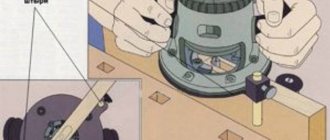
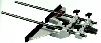
A rather expensive, but worth its price, device is a tenon cutter. Essentially, it is a complex and precision-made workpiece clamp, complete with a copying template. They work on it with a special copy sleeve. It not only rests on the plane of the template, but also “holds” onto it from the reverse side due to a small side. Two or four mating parts are fastened at once (from the other edge, each pair is worked separately), while special stops set the required displacement of the workpieces relative to each other. Next, set up the router. Clamp a specially shaped attachment (“dovetail”) and set the milling depth in accordance with the reference table. The density of the connection, that is, the gap in the tenon-socket pair, depends on it. With precise adjustment, it is not difficult to achieve a “zero” gap - after assembly, the structure will hold tightly without glue or other additional fixation measures. Such compounds are used, for example, in the manufacture of furniture from solid wood of valuable species.
It is easy to get connections for a straight tenon - you will need a different template and nozzle.
As part of our article, we briefly outlined the main technological operations, but in fact there are much more of them. Which is not surprising, since the router is even used for artistic purposes to apply engravings (again, with a special pen cutter). It is important to understand that this tool, with rare exceptions, is not a self-sufficient thing and requires all kinds of equipment and devices. Without them, he will hardly reveal even a quarter of his capabilities.
It is for this reason that you should treat your purchase as responsibly as possible, paying attention not so much to the device itself, but to the list of branded (some may not be suitable!) accessories for it.
CUTTERS
Working with a stop or guide and using a special cutter, make grooves for installing furniture hinges. For precise longitudinal positioning of holes, you can use a special tire that allows you to rigidly fix the position of the router at standard length intervals.
Some tenon joints are made using one cutter (a counter profile is not needed).
Special cutters required for making binding.
Special cutters required for making binding.
One of the cutters (profile) forms the edge of the part; pair (counter-profile) “pass” the end of the mating workpiece.
One of the cutters (profile) forms the edge of the part; pair (counter-profile) “pass” the end of the mating workpiece.
This equipment is easy to use and also allows you to mill curved edges.
This equipment is easy to use and also allows you to mill curved edges.
TENING DEVICE
1. Depending on the type of template, a cutter is installed. By adjusting the depth of its immersion, the density of the connection is set. It can be assembled by tension or with glue (it is necessary to provide a gap for it). Using special windows in the template, the longitudinal position of the workpiece stops is set and they are turned with the side corresponding to the template. Next, mating parts are clamped in pairs on each side of the template. They must be cleanly processed and fit tightly.
2.
3. A special copy sleeve is installed on the router. To increase the accuracy of vertical positioning, it has a lip on the support ring, which allows you to grip the template plate from both sides. Guided by the general rule of guiding the tool against the stroke of the cutter, the workpiece is passed from the center to the edge. It is recommended to make a trim first (pass the template along the protrusions without “going into” them) - this will avoid chipping.
According to the text of the tool center
Do-it-yourself copying bushings for a router
In some cases, the manufacturer does not equip the milling machine with such an important tool. To make this necessary device yourself, you will need a washer made of duralumin or sheet metal, and a plumbing extension made of metal with a thread. The manufacturing process is as follows:
In this article, we tried to briefly highlight the key points regarding bushings, talked about the method of their manufacture, and talked a little about such a useful tool as a copying ring.
Source
Features of copy rings
Copy rings are a round plate that has a protruding shoulder.
When the equipment is operating, the collar slides around the template.
With the help of this component, the necessary trajectory of the cutter is ensured.
The mounting location for this device is the base of the router.
Various methods can be used to attach it.
Most often it is screwed into the hole with a thread.
Some copying rings are equipped with special antennae that are inserted into special holes when they are attached to the cutters. Copy rings can also be screwed on. Screws are most often used for this purpose.
When choosing this device, it is imperative to pay attention to its size. In terms of its diameter, it should match the diameter of the cutter as accurately as possible.
In this case, the selection of the ring is carried out in such a way that its diameter does not come into contact with the cutting parts of the cutter. To compensate for the diameters between the ring and the cutter, templates are selected so that they are smaller than the finished parts.
Varieties of attachments for working with templates
Regardless of which router you choose, using a specific router attachment is important.
Today there are quite a lot of such attachments. Therefore, in order to get a high-quality result, you need to think carefully about which one to choose for processing your parts.
There are several types of attachments that will help you make it easier to work on individual sections of a wooden piece. So, while cone cutters are capable of creating a certain angle in wood, disc cutters are an excellent choice for cutting parts at right angles. For roundings, molding type attachments are used. But rebated and profiled attachments are perfect for artistic finishing of wood parts.
There are also very complex parts. Here it is necessary to carry out milling over them in combination, using one or another type of cutter. In this case, even for the same area, several different nozzles can be used. Usually such complex works have a certain artistic value. At the same time, if you do not have the opportunity to use different attachments, you can limit yourself to one main one. But in this case, the work will be long and will require much more painstaking work from you.
So, the main points on working with templates for wood milling have been discussed. If you take into account the above tips and sequence, carry out milling carefully and don’t rush anywhere, you can achieve good results and get beautiful, identical parts.
Buying a bushing.
The bushings are usually made of brass or steel. Honestly, I don't think one material has a huge advantage over the other. A router with a brass guide bushing is less likely to damage the router bit. Let's take a closer look at the type of brass bushing. Many steel guide bushings are stamped and do not have much precision, so they can result in inaccurate milling. Brass bushings can be shifted in order to correctly position themselves at the base of the router and coordinate the position of the bushing with the center of the cutter. This is important and always gives accurate results; such a bushing solves the problem of centering on the base of any router model.
A router with a guide bushing is required in templates where dovetail cutters are used. The jig kit often already includes the correct guide sleeve for use.
Often, the manufacturer of template rulers such as dovetail grooves will do the work of selecting the correct ruler and guide sleeve (photo on the left). If you want to use your own tools that use bushings, then match the two diameters, cutters and bushings before using them. As a rule, when routing for the first time, I choose a slightly smaller cutter. This provides the necessary margin, for example inside the groove, during preliminary milling. If you use a router as a slotting device, then you must take into account the size of the offset on both sides of the groove; when milling one edge, you need to take into account the offset on only one side. will always open up new possibilities and I think you'll agree that bushing guides are a great way to do that. They just require a little skill in setting up to make precise connections.
Since the milling machine is a widely used tool among amateur and professional carpenters, additional tools for it, such as copying sleeves and rings, will be indispensable when working.
In this article we will tell you how to make a copying ring for a router yourself, we will figure out what the copying sleeves are for, and how to handle them at work.
Wood bits
The type of specific task and the shape required to perform it significantly influences the equipment used for a hand router. Sometimes it is necessary to create grooves on narrow parts, and standard nozzles are not suitable for such work. In such a situation, you will have to use additional equipment, or make it yourself.
The following factors stand out as distinctive features of additional attachments:
- The use of specialized equipment for cutters allows you to limit the scope of the tool. This allows you to significantly improve the quality of the finished result (grooves).
- The design consists mainly of a base, which can have any, even the most bizarre, shape.
- Two pins are fixed to the base, which limit the movement of the router along the surface. Thanks to them the lines are straight
When making such a nozzle with your own hands, you need to know some subtleties. The guide pins must be located on the same strip with the center of the cutter used in the device. Only then is it possible to make a groove located directly in the center of the end of the material.
Important! Some nozzles are easy to make, but others have a complex shape, so they are easier to purchase than to create with your own hands. Increasingly, in stores you can find universal equipment that is used to create various items.
| Manufacturer | Anchor |
| Tool type | Dovetail cutters |
Cutting modes
In practice, the selection of optimal cutting conditions occurs experimentally, directly during production. This happens because the settings depend not only on the tool, but also on the machine, material, devices (AIDS system: Machine-Device-Tool-Part). However, you should rely on calculated values, which can be determined using lookup tables and formulas.
Feed per tooth
In this article we will analyze in detail what feed per tooth is and how to calculate this parameter.
Application of the ring
When using a milling ring, it is possible to mill according to a template. In this case, the same pattern is copied onto the workpiece.
Performing certain jobs requires not only carpentry skills, but also the ability to handle tools. For example, in order to install door hinges, you need to spend a lot of time.
To reduce it, a hand cutter is used, into which a copying ring is pre-installed. With its help, you can produce the most accurate milling of small parts.
The copying ring is designed to protect the template from the cutter. When the tool operates, a flange slides along the edge of the template.
It should have an optimal size that will allow the cutter to rotate freely during operation. That is why the distance between the cutter and this device is taken into account.
In order to find out the optimal distance between this device and the cutter, it is necessary to subtract the diameter of the device from the diameter of the cutter. The resulting value is divided by two.
This number will become the optimal distance between the cutter and this device. If templates are made that have numbers, then this requires increasing the distance between the cutter, the movement of which is carried out inside the template, and this device. In this case, the template itself should be a little larger.
In order to determine the movement characteristics of the cutter, a distance is added between it and this device. For example, if you use a 12 mm cutter and a copy ring whose diameter is 16 mm, then using this tool you can attach flush hinges for a folding table, the size of which is 30x71 mm.
Once the copy ring is installed, it should move five millimeters under the base.
To make a template, you must use a board whose thickness is at least six centimeters. You need to cut off a small piece from it.
Its size must fully correspond to the size of the tool, which will provide high-quality support. On one side, it is necessary to mark the place where the hinges will be attached.
After this, the distance between the cutter and the copy ring is added in accordance with the above formula.
Calculating the distance between this device and the cutter is quite simple. It can be produced independently, even by a master without relevant experience.
If the copying rings for the cutter are selected correctly, this will ensure the highest quality work.
Milling with copy ring
The copy ring (or bushing for a router) is a steel plate with a round hole in the center and a ring-shaped edge. It allows you to quickly create multiple copies of one part, which greatly facilitates the execution of labor-intensive small jobs, such as installing hinges for a door. In addition, the smooth base of the ring greatly facilitates the work of milling and ensures its accuracy.
One of the purposes of the copy ring is to protect the template from the action of the cutter, so its flange should be of such a size that it can easily move along the edge of the template without slowing down the movement of the cutter. To achieve the desired result, you must correctly calculate the distance between the ring and the cutter. It is calculated by the formula: subtract the diameter of the ring from the diameter of the cutter and divide by 2. If the templates contain numbers, then the calculated distance is added to them.
Calculation example for creating a template
The task is to prepare hinges measuring 30 mm by 71 mm to connect the parts of the folding table. Tools for work: cutter for grooves with a diameter of 12 mm, a copying sleeve with a diameter of 16 mm, when fastened, the ring moves relative to the base by 5 mm. A piece of board about 6 mm thick is suitable for the template. On the prepared base, mark the area where the loops are attached, from which 2 mm are counted (calculation using the formula: (16-12): 2 = 2 mm). Moreover, a correctly made template will be larger in size. In this way you can easily prepare signs with inscriptions and hinges for hanging doors.
The time spent on making the template will later pay off, since it will only take a few seconds to prepare the parts according to the template.
Do-it-yourself copying bushings for a router
In some cases, the manufacturer does not equip the milling machine with such an important tool. To make this necessary device yourself, you will need a washer made of duralumin or sheet metal, and a plumbing extension made of metal with a thread. The manufacturing process is as follows:
In this article, we tried to briefly highlight the key points regarding bushings, talked about the method of their manufacture, and talked a little about such a useful tool as a copying ring.
Ring technique
Copy rings included in the set
The operation of this device is quite simple.
When moving the router along the template, it is possible to obtain a pattern that fully corresponds to this template.
Using this method, you can easily make an eye-catching door sign.
Most often, this method is used when there is a need to install flush door hinges.
In this case, you have the opportunity to produce the template yourself. Several grooves are milled along it, into which hinges will later be installed.
Making a template is a fairly lengthy process. Despite this, the production of the grooves themselves will be carried out within a few seconds.
Very often, a ready-made template is purchased for milling. It must be clamped with clamps.
You need to insert the flange of this device into it, and then just turn on the router. Next, the cutter is placed into the part and the router is moved in accordance with the shape of the template.
Milling of parts using a template is carried out using a fairly simple technology. When milling, the template imprint is not made to the full thickness.
In this case, there is a small distance between such devices as the edge of the template and the milled groove.
In order to eliminate this defect, it is necessary to attach the loop in the appropriate place and circle it with a pencil. It is necessary to determine the distance between the cutter and this device in accordance with the formula described above.
Next, the template is cut out. To sand its edge, you need to use fine sandpaper. Milling should be done in two stages on both sides of the loop.
It is also necessary to cut out recesses for the hinge pins. This will ensure that you can get the same level between the surface of the material and the loops.
Copy rings for a router, a video about which is presented below, are an ideal option for obtaining the most accurate workpieces.
How to buy several products with one order?
Find the product you need. Click on the Add to Cart . Please indicate the quantity. After this, the product will appear in your cart. Similarly, place all the necessary items in the cart. Then click on the trash icon in the top right corner. After this, you will find yourself on the page with the selected products. If you don’t need to change anything, then click the buy , fill in your contact information and click the Send at the bottom of the window. If you need to remove something from your cart, click on the cross at the beginning of the line with the desired product.
Guide rail
The guide rail, like the rip fence, ensures the linear movement of the router relative to the base surface during wood processing. Meanwhile, unlike a parallel stop, such a guide for a router can be located at any angle to the edge of the workpiece. Thus, the guide rail can provide the ability to accurately move the router during wood processing in almost any direction in the horizontal plane. A guide rail equipped with additional structural elements is also useful when milling holes located in wood at a certain pitch.
Fixation of the guide bar on the work table or workpiece is ensured by special clamps. If the basic configuration of the device does not include such clamps, ordinary clamps will be suitable for these purposes. Some models of guide bars can be equipped with a special adapter, which is often called a shoe. The adapter, connected to the base of the router via two rods, slides along the profile of the tire during processing and thus ensures the movement of the working head of the router in a given direction.
Making a groove with a router using a guide rail
A milling device such as a guide rail is best used in conjunction with routers whose support platform is equipped with height-adjustable legs. This is explained as follows. In cases where the supporting surfaces of the router and the tire are in different horizontal planes, which can happen when the device is too close to the wood workpiece being processed, the adjustable legs of the tool make it possible to eliminate such a discrepancy.
Guide devices for equipping a router, which, despite the simplicity of their design, will be highly efficient in use, can be made with your own hands without much difficulty. The simplest of such devices can be made from a long wooden block, which is secured to the workpiece using clamps. To make this device even more convenient, you can supplement it with side stops. If you place and fix a block simultaneously on two (or even more) pieces of wood, you can mill a groove on their surface in one pass.
Milling along a wooden plank fixed to a workpiece
The main disadvantage that distinguishes the device of the above-described design is that it is not easy to accurately fix the block relative to the line of the future cut. The guide devices of the two designs proposed below do not have such a disadvantage.
The first of these devices is a device made of interconnected boards and plywood sheets. To ensure alignment of this device with respect to the edge of the groove being made, the following conditions must be met: the distance from the edge of the stop to the edge of the plywood (base) must exactly correspond to the distance at which the tool used is located from the extreme point of the router base. The device of the proposed design is used if the tree is processed with cutters of the same diameter.
Device for making grooves with a router
For milling operations performed with tools of different diameters, it is advisable to use devices of a different design. The peculiarity of the latter is that when using them, the router comes into contact with the stop with the entire sole, and not just its middle part. The design of such a stop includes a folding board on hinges, which ensures the correct spatial position of the device in relation to the surface of the wood product being processed. The purpose of this board is to ensure that the stop is fixed in the required position. After this procedure is completed, the board folds back and thereby frees up space for the working head of the milling cutter.
Device with folding bar
When making such a device for a router with your own hands, you should keep in mind that the distance from the center of the tool used to the extreme point of the base of the router must correspond to the width of the folding board and the gap between the board and the stop, if it is provided in the design of the device. If in the manufacture of this device you focused only on the edge of the cutter and the edge of the groove that needs to be formed with its help, such a device can only be used with cutters of the same diameter.
Often, grooves in wood blanks have to be milled across the fibers of the material, which leads to the formation of scoring marks. The amount of scoring can be reduced by devices that, by pressing the fibers in the place where the cutter comes out, do not allow them to break off from the surface of the wood being processed. The design of one of these devices consists of two boards, which are connected to each other with screws at an angle of 90°. The width of the groove made in such a device must match the width of the recess created in the wood product, for which cutters of different diameters are used on different sides of the stop.
Another milling device, the design of which consists of two L-shaped elements, fixed to the wood product being processed with clamps, is required for milling open grooves and ensures a minimum amount of scoring during processing.
Delivery across Russia
Delivery to the regions is carried out through transport companies (hereinafter referred to as TC) at the expense of the client. The calculation of the cost of delivery, as well as the choice of shopping center is carried out by the buyer independently. Goods are shipped only to the TK terminal in Moscow several times a week. For delivery from Moscow to the destination city, the Buyer pays directly to the shipping company upon arrival of the goods at the terminal in the destination city.
We work with the following shopping centers:
- Energy (2 times a week)
- Business Lines (2 times a week)
- SDEK (3 times a week)
Delivery is made ONLY after advance payment of the invoice, for both individuals and legal entities. Attention: When sending through a transport company, additional packaging and courier delivery of the order to the transport company's terminal may be required. Packaging costs from 80 rubles and courier delivery costs from 250 rubles. These additional costs and their final cost will be indicated when issuing an invoice for payment of the order after it has been agreed upon!
Delivery is also carried out by Russian Post (at the expense of the client). But some products, for example tenon saws, are delivered exclusively by transport companies. Because There are restrictions on weight and dimensions for postal items.
Attention! We reserve the right to change the delivery method if it does not increase the cost of delivery for the client, but significantly improves the delivery conditions (for example: cheaper, or faster, or closer to the residential address).
Pickup is also possible at the address indicated on the website, but by prior agreement.
Features of the production of devices
A copying ring is a universal device that is widely used for milling a variety of parts with a high level of accuracy. These products are characterized by:
Maximum precision in the production of workpieces when using copying rings is achieved thanks to their correct geometry. Copying rings are characterized by the presence of several standard sizes, which allows them to be used for various tools.
The production of these devices is carried out using universal technology, which ensures their excellent performance. For the manufacture of copy rings, heavy-duty metal is used, which limits the possibility of their breakage during operation.
Thanks to the presence of a special coating on the products, they are resistant to corrosion and other negative environmental influences.
Thanks to the ergonomic shape of this device, a high level of convenience is ensured during its installation on the cutter. These devices are quite small parts, which provides convenience during their storage and movement.
The copying ring is an integral part of the milling machine, with the help of which the most accurate work is carried out. For this purpose, you just need to select the right ring.
Milling and its features
Today, many people, when installing furniture, carrying out repairs, etc. need metal or wood processing. Milling is most often used for this purpose.
This is a process in which metal is cut. For this purpose it is necessary to use a rotating cutting tool.
Simultaneous feeding of the workpiece is carried out according to the linear principle. Removal of material from the workpiece is carried out using a cutter, onto which a copying ring is placed, to a certain depth.
When processing material, the work of the cutter can be carried out from the periphery or from the end. When the tool operates, the cutter rotates.
The copy ring rotates with it. The tool has peripheral and end cutting edges of the teeth, with the help of which milling is carried out. In this case, there is an increase in the cut thickness towards the center and a decrease in it upon contact between the cutter and the workpiece.
The copy ring is an integral part of milling equipment. With its help, templates are read, which greatly facilitates the process of working with a milling machine. Installation of this device on the router is carried out without the use of special tools, which allows anyone to easily perform this action.
In appearance, the copy ring resembles a round plate, which is characterized by the presence of a protruding collar. The rings are made of steel, which ensures long-term operation.
The copy ring is characterized by the presence of an internal and external diameter. The internal diameter of this device is a fairly important aspect, since this indicator is used to select it for a specific cutter.
With the help of copy rings, a milling machine not only produces blanks, but also rounds corners. To perform this action, it is necessary to use copying rings that match the cutter in diameter as closely as possible.
In order to make the procedure as simple as possible, you need to use a template. Quite often, an adjustable template is used.
With the help of copying rings, working with the milling machine is greatly simplified for the operator.
Despite the fact that these devices have relatively small dimensions and are almost invisible in a milling machine, they allow you to produce a variety of workpieces with maximum precision.
Instructions for working with templates
IMPORTANT: BEFORE USING THE TEMPLATE HOLDER FOR THE FIRST TIME, WE RECOMMEND TO MAKE TRAINING INSERTS ON THE BAR OR OLD DOORS.
The inserts are installed in the template holder so that the inscription is at the bottom. IMPORTANT: the difference in diameter between the copy sleeve and the cutter should be 4mm. See Fig.1
The difference in diameters (20-16) = 4 mm.
Offset (distance between cutter and copy sleeve) 4/2=2mm
An example of the relationship between copying bushings and straight slot cutters
20mm sleeve - 16mm cutter
18mm sleeve - 14mm cutter
16mm sleeve - 12mm cutter
14mm sleeve - 10mm cutter
12mm sleeve - 8mm cutter, etc.
Inserts are designed for copy sleeves no higher than 20mm
For the depth of the locks, the inserts are designed for a 20mm, 30mm, 32mm copy sleeve and a 16mm cutter. Bushing 30 and 32 are made to allow the collet nut to fit into the bushing while increasing the routing depth.
Loop insertion. Markings for installing the SD.
(If you have Vashablon MINI)
Before you start inserting the hinges, measure the thickness of the door and frame up to the seal; if the size of the door is larger than the size of the frame (Fig. 4), then we begin inserting the hinges from the door. If the size of the box is larger (Fig. 3), then we start the insert from the box. If the door and the frame are the same in thickness (Fig. 2), then you can start cutting in either from the frame or from the door (there will be no difference).
When inserting loops, the SD is installed at the place where the loop will be inserted. There is an o on the SD, this mark should coincide with the previously drawn line. Then we secure the SD with clamps.
The door is installed in the StroyProfi door holder, then measured from the top of the door 250 mm (if the hinge length is 100 mm), a line is drawn down with a pencil, the bottom hinge is marked in the same way, the line means the middle of the hinge. Next, we apply the pre-prepared box, with a 45-degree cut upwards, to the end of the door, where the line is located. We measure 3 mm from the bottom edge of the frame to the doors and fix it. We continue the line from the door to the frame from bottom to top.
(MAXI template) The MAXI template can be installed in 2 ways:
1 method is described above;
Method 2: at the edges of the template there are steps with a difference of 3mm. We install the short steps flush with the door, the longer ones - to the frame; if you install this way, you will get a distance from the edge of the door to the hinge of 200 mm. You don’t need to measure anything, the template measures everything for you. This method is simpler and less labor-intensive J.
Important: the edge of the front side of the SD must be in line with the plane of the door, only after this we fix it with clamps.
Select the size of the desired insert for the loop. Next, we adjust the platform with the insert. If the difference between the width of the loop and the thickness of the box is 10mm, then set the “loop” risk to 10. Fix it with the thumbs.
Example: t
Box thickness - 40mm, hinge width - 30mm. 40-30=10.
We adjust the router to the cutting depth and mill. We remove the SD, cut out the corners with a chisel and attach a loop. You no longer need to adjust the motor until you finish cutting all the hinges.
. When transferring hinges from doors to frames, you need to use a measuring ruler, with which you determine the distance from the hinge to the template. After inserting the first hinge, we install the template onto the insert of the second hinge; after inserting, without removing the template, we rest the measuring ruler against the template, and fix the second end on the first embedded hinge (this is the distance we need to transfer the hinges to the frame (door). When transferring, after cutting in the first loop, apply a measuring ruler to the beginning of the loop with the already measured distance, rest the template against the ruler and cut the second loop in. If everything is done correctly, the loop will be cut in like at the factory: evenly, tightly, neatly and beautifully.
Lock mortise.
When all the hinges are embedded, turn the door over with the lock side facing up. The distance is measured from the bottom of the doors and the SD is set by sampling on the clamping bar “Center of the lock handle” (picture below) with the center to the mark (if you have a plumbing lock 165-20 and the like), (if you have a magnetic lock 196-18 and the like , then we set double inserts according to the sample). Select the desired “lock face” insert. The platform with the insert is adjustable; if the door thickness is 40mm, then the platform with the insert is set with the “center” mark at 20mm. Everything is fixed with thumbscrews (there is no need to adjust the SD until the insertion is completed). We adjust the router to the depth of the lock face and mill it. Changing the insert
on the “lock body”, adjust the router to the depth, and mill it. If everything is done correctly, the lock will fit perfectly.
Transom insert
We install the SD on the edge of the door (where the crossbar will be located) at the extreme notch on the clamping bar. The center of the sample should coincide with the top edge of the door. We press with clamps. We install the “crossbar” insert; the arrow on the insert should show the direction of the top of the door. We mill the entire depth of the crossbar, turn the insert over and cut in the thin part of the depth. Afterwards we smooth out the transition of depths with a chisel. Install and screw the bolt. The installation is complete.
Double inserts (reversals) (interior latches, knobs, strikers)
The center of the double inserts (reversals) is set along the second sample (on the pressure rail) from the edge. We mill the first part, turn the insert over and cut in the second part.
Assignments of samples on the clamping strips: (old sample template)
( in earlier versions, there is no selection" center of the lock handle). You can draw it yourself by taking 35mm from the center to the right and 35mm to the left. This selection is used for plumbing lock 165-20 and similar ones. When inserting, the lock handle will be at the height that you measured).
On the new version of the template, the clamping bar is informative, all the data is written on it. Let us dwell in more detail only on the side engravings.
(center of universal inserts)
The template has an engraving on the sides of the clamping bar “TsentrUV”, many people ask this question. Now we will tell you WHY.
Mainly intended for universal inserts (UV), these inserts come with radius flags to make insertions of any length of a radius lock. To align in the center, measure the thickness of the door EXAMPLE: door thickness (TD) 40mm. divide by 2, we get a center of 20mm. On the “UV Center” scale we set it to 20. On the movable plate we set the mark with the letter “P” to 2mm on the “center” scale. That's it, the template is set for insertion using universal inserts with radius flags in the center. This procedure also allows you to embed the lock body with thin doors and a 32mm copy ring. without unscrewing or moving the aluminum support angle.
INSERT OF COUPE HANDLES
To insert compartment handles, we use the appropriate insert. Pull the pressure rail all the way and clamp it with the wings. We set the movable plate with the letter “P” on the scale to the center position zero (0) and boldly cut it in. Using these procedures, we set the distance from the edge of the door to the center of the insert to 50.5 mm.
More detailed information on inserts and working with the template holder can be found on YouTube or in the VKontakte group https://vk.com/stroyprofi2010
(group “StroyProfi, templates for inserting hinges and locks”), our website
www . template - master . ru
Subscribe to news and changes, leave your feedback, we will be glad to cooperate with you.
Exercise
It is necessary to attach flush hinges measuring 30 x 71 mm for the folding table. We will use a 12 mm groove cutter and a copying ring with a diameter of 16 mm. After installation, the copy ring is shifted 5 mm under the base. The template is made from a board with a thickness of at least 6 mm. We saw off a piece of board large enough to provide support for the entire base. On one side, mark the place for the loops and add the distance between the copy ring and the cutter: 16 mm - 12 mm = 4 mm, which we divide in half. That is, you need to add 2 mm.
Source
Set of cutters for router
Purchasing cutters individually is quite expensive. It's better to buy a set right away. A set, of course, has a higher cost than one cutter, but if you buy the same cutters separately, you will spend much more. There are many such sets and they are sold in any store. Let's look at the five most common sets from:
- The first set has six edge cutters with radii of 3, 4, 5, 6, 8 and 10 mm, equipped with a support bearing at the bottom. The shank of all cutters has a diameter of 8 mm
- The second set contains 12 cutters. By purchasing a set, you will receive two edge cutters with a radius of 6.35 and 9.5 mm and with a support bearing; one figured with two radii of 4 mm and with a support bearing; three end mills having a diameter of 6, 12 and 16 mm; one end with a diameter of 12.7 mm; one corner (90 degree angle) with an outer diameter of 12.7 mm. The set also contains one groove cutter with a radius of 6.35 mm; one end radius with a radius of 6.35 mm and a support bearing; one end mill with an angle of 45 degrees with a support bearing, as well as one slotted (dovetail) with an end diameter of 12.7 mm and an angle of 14 degrees. Such a large set will become a faithful assistant to a beginning carpenter, because it will help to implement different types of work on creating simple pieces of furniture
- the third set contains 16 items. It is very similar to the previous one. In addition to those described above, in the set you will see end mills with a diameter of 3 and 12.7 mm; slotted with a radius of 3.2 mm and a special drill with a diameter of 6.3 mm
- The fourth set is intended for professional craftsmen. The set contains 12 reinforced cutters with all the functions of the second set
- The fifth set has some similarities with the fourth, but includes 20 cutters of a reinforced design with a wide variety of characteristics and the addition of an end groove cutter with a width of 9.5 mm and a diameter of 32 mm. The set is also intended for professional craftsmen.
In addition to the sets described above, there are 10 more sets equipped with cutters in various combinations. The choice of sets is quite wide, any master will choose the right one for himself.