03/19/2021 Author: VT-METALL
Issues discussed in the material:
- 4 main ways to weld pipes together
- Professional marking of pipes for subsequent welding
- Options for marking pipes before welding for beginners
- Types of corner joints
- Welding technology
- 3 methods of welding profile pipes at right angles
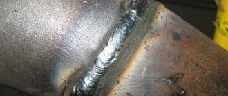
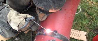
Welding pipes at an angle has its own nuances. It is somewhat more complicated than other methods of connecting structural elements. To do this kind of work well, a specialist must have certain knowledge and experience.
On the other hand, thanks to such welding, there is no need to use various kinds of bends, tees and crosses to assemble the pipe system. And it is simply unreasonable to miss this opportunity to save money.
Professional marking of pipes for subsequent welding
Transferring the required dimensions from the drawing to the pipe to create a part or part of the pipeline is called marking. This process is an important and responsible operation that requires precision execution. A specialist applying marks must be able to read drawings well, as well as have a developed imagination, be able to make geometric constructions and draw developments, understand the size of allowances for subsequent processing of parts and pipes, take into account the consumption of materials, using different trims in order to save money.
VT-metall offers services:
When marking for geometric constructions of signs and lines, measuring tools and templates are used. The list of basic devices can include a ruler and a square, a compass and a tape measure, a protractor and a scriber, a level, a bore gauge, a center punch, a surface planer, a hammer and a caliper.
In addition, templates should also be used. They are used for marking parts of the same type. The material for production is mainly roofing felt, tin or cardboard.
To apply signs and marks, chalk paint with various admixtures consisting of liquid glass or wood glue is usually used. For one liter of water, it is enough to take 120 g of chalk and 7 g of wood glue. The surface is painted with this solution, then marks are applied with a scriber and, to prevent their abrasion, they are punched. To avoid inaccuracies and errors, using chalk for such purposes is unacceptable.
We recommend articles on metalworking
- Steel grades: classification and interpretation
- Aluminum grades and areas of their application
- Defects in metal products: causes and search methods
Welding of fixed pipe joints (with the pipe positioned at 45°)
| Network of professional contacts of welding specialists. |
Topics: Pipe welding, Welded joints, Welds, Manual arc welding.
The peculiarity of welding is the location of the seam in space. It is necessary to have skill in welding seams in all spatial positions.
The root of the seam.
Let's look at Figure 1. Roller - 1 is made with an electrode with a diameter of 3 mm and a narrow roller from the ceiling position. Welding current is in the range of 80-95 A for all positions. The pipe is divided into 2 sections by a vertical axis. Each section has three (I, II, III) positions. Position I is ceiling-horizontal, position II is vertical-horizontal and position 111 is bottom. “Locks” are performed in the same way as described in section 3.6. The arc is short.
When welding the ceiling-horizontal position, the electrode should be tilted at 90° to both surfaces of the pipe. Begin welding with a backward angle. After passing the lowest part of the seam, switch to welding “angle forward”. When welding vertical-horizontal position (II), maintain the weld pool as when welding vertical seams, only with a constant horizontal displacement of the 1st section to the left, the 2nd section to the right. Welding should be done with a forward angle, as shown in Fig. 68. Finish welding position III as the bottom position, with the electrode tilted 90° to the pipe surface.
Figure 1. Root of the seam.
Filling the cut.
Two options are recommended:
First option. The second bead (second layer) is performed in one pass with an electrode with a diameter of 3 mm at an increased welding current, melting and connecting the lower edge - the root bead - and the upper edge. The welding speed is lower than when welding a root bead. Electrode manipulation is transverse and minimal.
Second option. Perform the second layer with an electrode with a diameter of 3 mm (Fig. 1) as follows. The ceiling and lower zones are performed in several passes depending on the width of the cut. The vertical zone is performed in one pass. The first roller (2) in the ceiling position is performed on the lower part of the groove, which is like a shelf 1-1.5 times the diameter of the coated electrode, like surfacing in the ceiling or horizontal position until the position (vertical-horizontal) when it is necessary to switch to vertical welding . Start the second roller (3) by 5-10 mm from the beginning of the first roller, which is the platform for the second one. The welding technique is the same as for the first roller. Having reached the horizontal level of the (2nd) roller (it is not advisable to stop or replace the electrode at this point), begin welding across the entire width of the groove, melting the crater of the first roller. The welding technique is similar to vertical seams, only with each step the electrode is manipulated, in addition to lifting, by moving the electrode horizontally, trying to maintain the layer width gained in the ceiling position with two rollers. In this way, welding is carried out to a position (lower) when it becomes difficult to control the liquid pool over the entire width. In this case, it is necessary to switch to welding in several passes in the same way as in the ceiling position. Finish the first roller behind the horizontal line as far as possible, but without allowing any leakage or overhang of another section over the previous seam. Finish the next roller a little earlier by 5-10 mm than the first. Each previous roller is a platform for the next one, this contributes to the normal control of the welding process. In the same sequence, perform the second half of the butt joint (2nd section), having previously (if necessary) cleaned and trimmed the beginning and end of each pass. Subsequent layers (Fig. 2) are performed in the same way, not forgetting to leave in each layer an unfilled groove for the width of the coated electrode between the penultimate roller and the upper edge of the groove in the ceiling and lower zones. When welding large thicknesses, the vertical-horizontal zone with a large groove width is also performed in several passes.
| Figure 2. Welding subsequent layers. | Figure 3. Welding the face layer. |
The recommended method allows high-quality and efficient (due to the use of increased welding current) to make butt joints of pipes at 45°.
Facial layer.
The face layer is performed using the same welding technique as filling the groove. Make the last bead (7) with an electrode with a diameter of 3 mm, avoiding undercutting in the upper part of the seam. Rollers 1, 3, 4 and 6 are, as it were, additional to maintain the width of the seam in the ceiling and bottom positions.
Copyright. When quoting any materials from the Site, including messages from forums, a direct active link to the weldzone.info portal is required.
weldzone.info
Options for marking pipes before welding for beginners
The process of welding pipes at an angle is somewhat difficult for novice welders. First of all, you need to mark the pipe, then cut it straight using a grinder and weld it into another. What subtleties are there? How to cut a pipe at an angle correctly and quickly?
It is especially easy to weld pipes at an angle of 90° or 45°, and use a regular piece of paper to mark it. You need to fold a square sheet of paper diagonally. Thus, we obtain the simplest template for applying an angular marking line.
You can use some kind of container with water for such purposes, but this method is suitable for marking pipes of small diameter. Having tilted the container to the required angle, lower the pipe vertically into the water, then remove it and trace the resulting mark line.
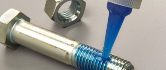
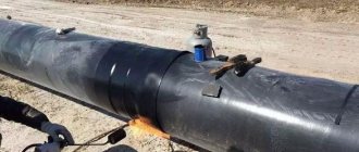
In addition to the previous option, there is another simple way to mark pipes for welding, which involves using a small metal corner. It is lightly grabbed with an electrode in the place where it is planned to weld the pipes at an angle, and after that the welded pipe is outlined with chalk along it.
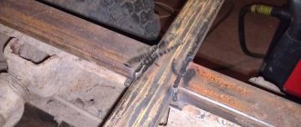
The next method for quickly marking pipes and then welding them at an angle is using a device in the form of long skewers with rubber bands. For this type of marking, you need to place the welded pipe next to another, putting two rubber bands on it, and then insert the skewers tightly. The required angle is achieved by pulling out the skewers, then cutting the pipe.
Upon completion of the marking, you need to take a pencil or sharpened chalk and draw a line on the surface of the pipe along the edges of the skewers. After this, when cutting the pipe along the marking line, the correct angle for welding is obtained.
There are other high-tech methods for marking pipes at an angle during welding, for example, using computer programs. However, such technologies are rarely used; simple methods are mostly used.
Marking using a sheet of paper
One of the easiest ways is to mark the corner using a sheet of paper. We fold the square sheet strictly diagonally. We take the pipe and wrap it with a folded page so that the edges of the diagonals are opposite each other. So, on the smaller side of the page we have an angle of 45 degrees. We take any marking tool and mark the location of the future pipe cut along the line of the page. To prevent the markings from being accidentally erased, you can use narrow tape. This marking method is convenient for a long pipe of enormous diameter, and the cut point of which is somewhere in the middle.
Types of corner joints
The main regulatory document controlling the welding of pipes at an angle is GOST 16037-80, which reflects that, in addition to five methods for welding tees (crosses), there are also eight methods for joining sectors in a bend (elements in a track). In addition, angular coupling, meaning the joining of highways at any angle, is carried out using the following types of connections:
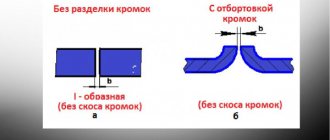
- Corner joint - with the same diameter without an edge bevel using a one-sided weld. This method is enshrined in GOST - U16. The edges of the pipes are made with virtually no gap, and the projection of the mating line is the geometric figure of a triangle.
- Fillet welding of a fitting or pipe (welding or extension) - with a one-sided weld, regulated by GOSTs U17, U18. The projection of the welding joint is in the shape of a semicircle. The edges must fit together with a minimum gap.
- Connection with beveled edges and one-sided seam, code U19. The conjugate line resembles a sector of a circle. The end of the lower pipe is essentially untreated; the chamfer is removed only on the upper pipe.
- A connection that has a beveled edge at the cylindrical end, made with a one-sided seam (code U20). When projecting the connecting lines, an arc sector is obtained, and the edges of the lower pipe also cannot be processed.
- With the division and placement of an annular liner inside the pipe on a one-sided gasket. The seam is applied from the outside and marked in the assembly technical documentation as U21.
45 degree cutting
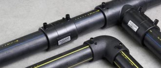
Typically, in order to rotate a pipe by 45 degrees, fittings and bends with a rotation angle of 45 degrees are used, made of the same material as the pipes themselves; if the pipes are steel, then the turns are welded from steel. For HDPE pipes, there are electric-welded or cast bends at 45 degrees (note that it is almost impossible to find compression fittings with this angle of rotation in Russia).
But, if you still need to cut a round pipe made of steel or various types of plastics, then for this you will need a pattern for cutting pipes at an angle, the shape of which is calculated manually or by machine. The task is greatly simplified if it is necessary to cut a square metal profile at an angle of forty-five degrees.
For quick cutting, you can use a regular sheet of paper folded diagonally to mark the surface for future cutting. When using folded paper, proceed as follows:
- carry out on a straight surface of the profile in the place where the cut is made, strictly perpendicular to the line;
- apply a sheet of paper folded diagonally to the side surface with the sharp end to the line so that the upper edge of the paper triangle is flush with the top side of the metal profile.
Rice. 2 Homemade template for cutting pipes at 45 degrees
- draw a line with a pencil along the side of the sheet at an angle of 45 degrees, after which the paper corner is applied to the other side and traced with a pencil (it is better to use a thin marker).
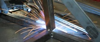
For sawing, you can use a grinder with a metal disc, first drawing a thin line along the marking, and then gradually deepening it until the edges are completely separated.
When working with an angle grinder, the following factor must be taken into account: if the edges are completely cut, the disk may be damaged by a sharp corner, which will lead to its failure, and in the absence of protection on the angle grinder, even to injury to the worker. Therefore, it is advisable not to cut the corner edges to the end, but to leave a narrow groove and then break them off, subsequently grinding the protrusion.
Making a template for cutting metal profiles
If you need to cut a large number of pipes, you can make a template from a metal profile of a larger diameter using a paper sheet using the above method. The angle of inclination is checked with a protractor or a construction square - in this case, the two edges of the cut parts of the template are connected.
When working, a template is placed on the part to be cut in the right place and pressed tightly, the markings are applied with a sharply sharpened scriber while tracing the template outline. The part is cut in several passes with a gradual deepening of the groove.
Rice. 3 Cutting a metal profile using a miter box
DIY miter box for cutting pipes
Using a template is not very convenient - you have to make a cut along the line, holding the grinder in weight, which leads to large errors. If you have a welding machine, you can make a simple miter box - guides for the grinder disk, preventing it from moving to the side.
To do this, use a previously made template, drill a hole in the side of which and weld a nut. When working, a homemade miter box is placed on the profile, a bolt is screwed into its nut and the device is pressed against the profile surface. A grinder with a metal disc is used to make a cut, lightly pressing the disc against the side surface of the device. It is clear that with prolonged use, the edges in the miter box are gradually ground down, and although the process occurs simultaneously on all edges, some errors will appear over time. Therefore, it is better to make the device from hard, wear-resistant metal in order to increase its service life and obtain a more accurate instrument.
Welding technology
Gas, argon arc or electric arc welding without the use of edge bevels begins with adjusting the ends. The minimum gap between the pipes in this case is 0.5 mm, and the maximum is 1.5 mm. In addition, this technique can only be used with pipe wall thicknesses from 1 to 6 mm. The process must begin by tacking the corner joint with spot welds, then correct the location of the pipes and weld the joint from the outside along the entire diameter.
For angular mating with a one-sided end, it is assumed to produce a chamfer with an angle of 50°. And with a double-sided section, it is assumed that two chamfers are used, made at an angle of 30°. In the first option, the gap between the edges is 1-2 mm, and in the second – 2–5 mm. In other words, you practically don’t have to worry about the correct execution of the end surfaces. With this joining method, the pipe wall thickness ranges from 2 to 20 mm.
Computer program to help
I would also like to consider the method of marking using a computer program. This is a super complicated method for those who are not used to working with a computer. It requires knowledge of a PC, programs for developments and drawings. We begin work by making a drawing indicating the size of the circle and the slope. We make a so-called virtual template.
After this, we print the image on a sheet of paper using a printer. The larger the diameter of the pipe, the more pages with markings there will be. Using scissors, we cut out all parts of the drawing and, using tape, glue them together. The finished template is applied to the pipe, and we make markings along the edge of the paper. This marking method is considered one of the most correct. If your computer does not have such programs, you can use the Internet. It is possible to download a pattern for marking on the Internet. In addition, you need to print it on a printer and cut it out. We wrap the finished pattern around the pipe and make markings.
Mistakes when soldering plastic pipes
An inexperienced plumber or owner who decides to carry out the installation of a polypropylene water line with his own hands often makes mistakes, not fully knowing the technology of pipe soldering and not knowing how to work with a soldering iron.
The most common errors include the following.
Rice. 8 Differences between budget and expensive irons
Wrong choice of soldering iron
The most popular and inexpensive devices for soldering are electric couplings with attachments for different diameters of PPR. When purchasing and using, you must consider the following factors:
- You need to purchase the device with a convenient holder so that you can easily and quickly install it in place when working independently. This will reduce the time that heated elements are in an undocked state, which can lead to cold welding and further depressurization.
- It is also better to choose the units used with the regulator and power buttons placed in such a way that you do not touch them with your hand during operation, thereby lowering the temperature or turning off the heating.
- If the device is used for regular use, it is better to purchase an expensive model with high-quality Teflon nozzles - this will prevent polypropylene from sticking and improve the quality of connections.
Rice. 9 PPR heating table
- Modern devices are produced with electronic indicators that maintain a constant temperature using a built-in processor, which is reflected on its display. This factor also helps to improve the quality of soldering, the time of which is determined based on the degree of heating of the couplings, which cannot be determined on old-style units.
- The device must maintain a given temperature, which increases with increasing pipe diameter. Many Chinese irons have high temperature parameters, which should be taken into account when choosing a manufacturer; Turkish-made models are considered to be some of the best units in terms of price and quality ratio.
- The shape of the iron and the location of the couplings play an important role in cases where polypropylene pipes are welded in hard-to-reach places. A narrower iron and placement of the couplings on the edge of the pointed end in this case are much more convenient to use.
Repay
Overexposure of elements in the soldering iron for more than the required time leads to their surface overheating and after connection, accompanied by excessive force, the pipe passage becomes clogged with molten plastic. If such an error occurs at a large number of joints of heating or water pipelines, the system will not be able to function normally. In order to avoid this situation, you should strictly follow the time intervals specified in the instructions for each type and diameter of pipes and carry out several test solderings of small sections.
You should also always clearly mark with a pencil the distance to which the pipe is deepened for a diameter of 20 mm. it is usually 14 - 17 mm.
Low heating, incorrect angle and other errors
Many beginners make a fairly large number of mistakes, which include the following:
- Soldering of dirty elements near the walls or with water remaining in the line, while due to dirt or water cooling, the plastic does not connect well and subsequently depressurization of the joint occurs.
- Insufficient deepening of pipes into sockets of larger diameter. It often occurs when there is a minor error in the installation of faucets - if its valve is not turned at a small angle, the air in the joined area will not have an outlet, preventing the mounted area from being completely immersed in the hole.
- If the elements being connected are not heated sufficiently, the plastic will not have a uniform structure and the joint will depressurize. This defect can be identified by the absence of a skirt at the edge of fittings with a large diameter.
- When manually joining elements, a single axis must be maintained - otherwise distortions will lead to insufficient density and depressurization.
- Also, after joining, the joined area should be kept motionless for a certain time until it cools completely.
Rice. 11 Method of repairing polypropylene pipes by heating the surface of the pipe being repaired with a nozzle
To ensure high-quality soldering of polypropylene pipes in hard-to-reach places, you need to choose the right soldering iron - the model should provide easy access and the required heating temperature without sticking of the PPR. For convenience, all work is divided into two stages - first, long chains are installed in a convenient place, and then they move to the walls, joining sections in weight.
]]>
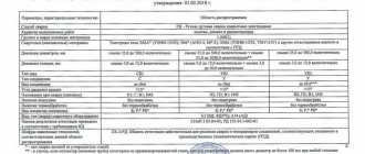
Selection of welding materials (electrodes, gas, etc.)
The choice of welding materials is made based on the material from which the pipes are made. Most often it became 4 groups:
- Low alloy and structural.
- Carbonaceous.
- Heat-resistant alloyed.
- Highly alloyed.
Welding electrodes for low-alloy, structural and carbon steels are very similar. Typically the following brands are used:
- SSSI 13-55;
- TMU-21U;
- TsU-5;
- SSSI 13-45
- TMU-46, etc.
For heat-resistant steels (KhM steels operating at temperatures of 500-570°), the following grades of electrodes are used:
- TML-1U;
- TsL-39;
- TML-3U, etc.
High-alloy corrosion-resistant steels are welded with electrodes:
- TsT-15;
- TsT-26;
- EA-400/10U, etc.
New electrodes must be tested before welding pipelines. When checking, you need to pay attention to the appearance of the electrode coating, which should not have chips, swelling, or sagging of the coating.
After a visual check, you need to try to weld a test piece with electrodes, and you need to pay attention to how the arc is ignited. The arc should ignite easily and burn stably. The electrode coating should melt on all sides without forming an overhanging peak, and the slag should be easily removed (in the case of rutile electrodes, it falls off on its own).
If the argon process or semi-automatic welding is used, then in this case a welding wire is used. The choice of wire as well as electrodes is made according to the type of steel being welded. For welding in argon, solid wire is used, and for semi-automatic welding, both solid wire and flux-cored wire are used.
The following wires are used for low-alloy and structural steels:
- Sv-08G2S;
- Sv-08GS.
For alloyed heat-resistant steels, the following grades of wire are used:
- Sv-08ХМ;
- Sv-08HMFA;
- Sv-08KhGSMFA, etc.
The most commonly used gases for steels are:
- Pure argon.
- Argon mixed with helium and/or carbon dioxide.
- Pure helium.
- Pure Carbon dioxide (CO2) - for semi-automatic.
Non-consumable electrodes that are used when welding in an inert gas environment are selected in accordance with GOST 23949-80:
- Made from pure tungsten.
- Made from tungsten with lanthanum oxide.
- With thorium oxide
- Tungsten with yttrium oxide.
The most commonly used electrodes are made of pure tungsten, marked - EHF.
Do you know how much an oxygen cylinder weighs? If not, follow the link.
Welding of pipelines at low temperatures
If there is a need to carry out welding work at sub-zero temperatures, a number of requirements must be met that will ensure high quality welded joints.
- Immediately before tacking, the metal in the area of the welded joint must be heated to a temperature of +20 - +40 degrees (so that you can hold it with your hand);
- the metal is heated before welding;
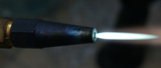
- It is possible to heat the metal using a gas flame method (cutter), as well as using an inductor.
Necessary tool for soldering small diameter polypropylene pipes
The thermal diffusion method used for welding polypropylene elements is realized by heating them with special devices, usually called soldering irons or irons. Structurally, the unit is a steel body with a built-in heating element, to which cylindrical heaters (nozzles) are screwed, the dimensions corresponding to the standard outer diameters of polypropylene pipes.
The temperature is set by a mechanical thermostat and two switches; in more modern devices, an electronic temperature indicator with processor-controlled heating is installed. The majority of irons have a flat shape; a less common variety has a round heating element, the nozzles on which are fixed with double-sided clamping screws.
In addition to the iron, the following tool is required for welded installation of a polypropylene line:
- Scissors. Designed for cutting polypropylene pipes, they are often supplied with a soldering device.
- Pencil and tape measure. The tool, as well as a corner and a knife, are used to accurately measure and control the location of the cut areas and remove the internal chamfer.
- Set of connecting fittings. Includes straight and angle couplings, tees, taps, threaded fittings and other fittings used to change the direction or connect plumbing fixtures to the main line.
- Household chemicals. Substances may be needed to degrease the welded surface and clean it from dirt.
Rice. 3 Tools for working with PPR
Features of soldering in corners
Soldering under such conditions is no different from carrying out similar work on other sections of the walls, with the exception of some factors.
Fillet welding requires precision and compliance with increased requirements for the geometry of a right angle; a square is used to check it. To join the sections, special corner couplings with a rotation angle of 90 degrees are used, which should be purchased together with pipes from the same manufacturer - this will ensure high adhesion between the connected elements.
Rice. 5 Sequence of soldering a PPR pipeline
How to weld a pipe under clearance
There are few real specialists in electric arc welding of steel pipes. This work requires meticulous precision and a lot of practice. Welding the root seam is the most critical stage of the process.
The highest quality connection of steel pipes of any size is provided by electric arc welding. The parts being connected melt under the influence of an electric discharge. The article contains visual lessons on welding.
Technology of electric arc welding of metal pipes
Electric arc welding has technological standards and specific features depending on the material, wall thickness and intended purpose of the pipes.
Welding of fixed pipe joints
The connection of fixed joints is carried out in three ways, which depend on the location:
- vertically;
- horizontally;
- at an angle of 45 degrees.
The vertical method includes 4 stages:
- Welding a pipe to create a root bead. The most important stage is the formation of the joint, which will be the basis for all work. The inclination of the electrode relative to the surface: “backward angle.” The length of the arc should be adjusted: if penetration is insufficient, set it to short; if it is normal, set it to medium. Keeping the weld bead in a liquid state for a long time leads to the occurrence of defects. Therefore, with a large volume of the weld pool, the welding speed is reduced.
- Welding three beads and sealing. The rollers are performed at high speed. Depending on the direction of the slag, rectangular or “backward angle” welding is used. The top edge of the last roller must have a minimum value up to the top edge. Usually equal to the diameter of the electrode.
- Forming a lock at the beginning and end of the rollers. The formed lock is the beginning of the roller with a 5 mm offset from the previous one. When making a joint, the roller must be continuous along its entire length.
- Welding on the front side. It is performed at high speed and aims to form a flat surface. Welding ends when it goes beyond the beginning of the seam.
The horizontal method requires professional skills. It is produced at different welding current values and at different angles to the part. This technique involves three stages:
- ceiling;
- vertical;
- lower.
Within one stage, welding takes place continuously, starting from the “backward angle” position and ending with the “forward angle” position.
Welding at a pipe angle of 45 degrees begins with creating the first bead at an electrode angle of 90 degrees. The seam is made by continuously melting the second roller. After filling the base, the first roller is melted. This creates connections horizontally and vertically.
Welding pipes “under clearance”
The technology provides the following conditions:
- dullness size: 2-2.5 mm;
- gap between edges: no more than 3 mm;
- opening angle: in the range from 60 to 70 degrees;
- additional processing of edges by chamfering to give them the required shape and eliminate irregularities;
- the difference in the thickness of the welded walls should not exceed 3 mm or 10%.
Welding of high pressure pipelines
A feature of welding high-pressure pipelines is the need for preheating of the joined elements to 300 degrees C, which is maintained throughout the entire tack and welding process.
When cooking gas pipelines, take into account:
- That thick-walled pipes are used for gas mains, which increases the overall labor intensity of the work.
- There are increased demands on the quality and reliability of the weld, so professionals with extensive experience are involved in the work.
- The entire system as a whole (pipe, as well as joints, welds) must be resistant to corrosion. After the end of cooking, to relieve thermal stress, a section of 10 cm in each direction from the seam is heated to 500-600 degrees C. For this, thermal ovens, induction heaters, and gas burners are used.
When heated, the ends of the pipes are closed to prevent cooling and air movement in the pipe.
Automatic welding
The so-called submerged arc welding involves feeding an electrode wire into the combustion zone of an electric arc using an automatic welding head. In the molten state, the wire metal enters the weld pool and mixes with the base metal.
Automatic welding allows:
- speed up and stabilize the process;
- make the arc invisible;
- expand the range of parts in thickness;
- make the seams more resistant to the formation of cracks and pores.
Flux has a positive effect on the stability of the arc and the chemical composition of the weld. To carry out automatic welding, the ability to rotate the joint is necessary.
Welding large diameter pipes
In more than half of the cases, the connection of steel main pipelines is carried out using pipe welding machines. When it is impossible to use the mechanical method, for example, due to localization features or limitations in manipulating the pipe, manual welding is used, carried out by a team of welders.
For main pipes with a wall less than 6 mm, two layers of welding seam are used, and more than 6 mm - three. The reverse roller of the root seam can have a height of up to 3 mm. In those places of the root weld that are welded poorly, additional welding is carried out from the inside of the pipe. This requirement also applies to that part of the root that was made in the ceiling position: the lower quarter of the joint perimeter is welded from the inside. Rotary joints require welding along the entire perimeter of the joint. Welding is carried out with 3-4 mm electrodes.
Large diameter pipes require the use of special centering equipment.
Welding steel pipes “through transmission” - step-by-step instructions
Pipes with thick walls, in which 2 mm is only the amount of dullness, are welded “through the light”.
Preparation and cutting of edges
The abrasive method is the least reliable due to the introduction of abrasive particles into the metal, which interferes with high-quality melting and leads to the appearance of cracks.
- Use a double-sided Y-shaped symmetrical groove with an angle of 65 degrees, an optimal amount of bluntness and a gap of 2 mm.
- When preparing bevel edges, use thermal or mechanical methods. Due to the high cost of thermal cutting (laser, plasma), various types of mechanical processing are used in practice, which make it possible to obtain a plane with high accuracy:
- processing on a milling machine;
manual bevel processing;
- cutting using abrasive wheels;
- processing with slotting-type edge cutters.
- Clean the joints of the welded products to white metal. There should be no irregularities, burrs or rust left.
- Treat surfaces with acetone or any similar substance. The presence of grease, dirt, and dust prevents the high-quality connection of metal molecules.
Centering and joining of pipes
- Centering and joining of small-diameter products is carried out by fixing them using improvised means or using assistants.
- Center large pipes (from 60 mm) with special equipment - a centralizer: internal or external. Both have an electro-hydraulic drive. Internal ones are more preferable due to the fact that when they are used, the joint remains uncovered. This allows the use of automatic welding machines, and also does not limit manipulations during manual connection.
- Do not allow deviations when using the manual alignment method. It is impossible to dock perfectly without a centralizer, but try to minimize the deviation.
- Having connected the pipes exactly, proceed to welding the root seam.
Root welding
- Cook the seam under the following conditions:
- minimum current;
- reverse polarity;
- short electric arc;
- dry electrodes;
- lack of wind in the pipe.
- Cook vertically, the electrode is perpendicular to the plane.
- Use an electrode to melt the edges - a bridge will appear between them, which is called a weld pool. In front of the jumper there is a so-called technological window.
- Carefully monitor the size of the technological window: throughout the entire process it should remain the same diameter.
- Make a root seam no more than 1 mm high. The return roller should also not exceed this value.>
- Clean the beginning and end of the seam and the transition area between the electrodes to avoid the formation of pores in the metal, the presence of which will sooner or later lead to loss of the pipe’s tightness.
Filling and capping of the weld
- After welding the root, fill the entire seam section.
- Depending on the wall thickness and material, use a single-layer or multi-layer penetration method.
- The movement of the electrode during filling is a triangle: edge 1 - edge 2 - technological window.
- Pay attention to the heating of the edges and root seam. The greater the heating, the wider the filling step.
- After each layer, clean the surface of slag.
- If you have the skill, and if the wall diameter allows, fill and cover in one pass.
Video lesson on welding pipes under clearance
Welding special gas pipes for transporting high-pressure contents places increased demands on the process.
Gas pipe welding technology
Features of welding pipes for transporting high-pressure trains are determined by two characteristics:
- Thick walls and small diameter.
- Aggressive effects of transported gases.
Pipes up to 10 cm in diameter are welded manually, above - using semi- or automatic welding with manual welding of the root of the seam. For diameters greater than 6 cm, special rings are used. The weld is made multi-layered - from 4 layers and above, depending on the load on the pipeline and the characteristics of the material. After completing the work, a mandatory inspection is carried out - flaw detection inside and outside the welding site.
Yulia Petrichenko, expert
Video lesson on welding gas pipes
- A large current when cooking the root leads to the formation of a hole instead of a technological window through which the metal will drip down. Provide a current of such strength that the metal has time to cool literally immediately after the movement of the electrode.
- If the process window is not visible, most likely the current strength is too low, and it must be increased.
- A small bluntness leads to an increase in the technological window and to sagging of the metal inside the pipe.
- A gap of more than 2 mm guarantees the appearance of pores in the seam - the work will be unsatisfactory.
- When welding with an electrode, you cannot make jump movements of more than 5 mm in length.
Welding steel pipes is not an easy task for a beginner. With practice will come experience and an intuitive feeling of what should be done and at what moment in order for the weld to come out perfect.
Perhaps you are a professional welder and have something to share with your readers. Leave your opinions in the comments.
protryby.ru
Welding and installation of a separate part of the pipeline system
When soldering a polypropylene water main, they always try to install individual sections of the water supply in a place with large free space and at a convenient height. To do this, you will need basic tools, a drawing of the highway and the correct procedure for carrying out the work.
Typically the hardest side to weld is on the wall with the two corner fittings, so it is welded first and secured with clips or dowel sleeves. Afterwards, from the corner fittings, further installation of sections of the line is carried out, moving on to soldering work directly near the walls. For ease of installation, it is necessary to provide in advance a place to install the soldering iron on a stand or organize its hanging.
Soldering polypropylene pipes in hard-to-reach places
When deciding how to solder polypropylene pipes in hard-to-reach places, the following factors should be taken into account.
Working with polypropylene pipelines in narrow places is more difficult than welding on straight pipe runs in conditions of sufficient space. Inconvenient places usually include areas near the top of the ceiling, spots in corners, and tight space conditions that make it difficult to install the soldering iron on the stand. In the latter case, you cannot do without outside help; an alternative solution is a special hook, prepared in advance in a convenient place, on which you can hang a soldering iron.
If the soldered pipe sections are located too close to each other on the wall, a special technique is used - the direct and mating parts of the joint are heated in turn. In this case, the first section is heated a little longer than the allotted time, and then the pipe is heated for a shorter time and, if possible, at a higher temperature (the regulator is set to a larger diameter).
The situation when the soldered sections must be of a certain length, but when welding them in line with a soldering iron, one of the parts will have to be cut to the width of two nozzles and a heating iron, can be solved in another way. A similar nozzle is purchased, fixed on the heating platform, and each of the segments is simultaneously soldered in different planes, after which they are connected. Using this method, you can mount not only straight sections, but also turns on walls, thereby ensuring a tighter fit of the line to the curved surface.
Rice. 4 Soldering polypropylene pipes in hard-to-reach places with an iron with two nozzles
READ ALSO: What Can Be Made From Polypropylene Pipes for a Garage