Device Features
The station has the following advantages:
- Settings menu.
- Two “memory” buttons, that is, two preset temperature modes for a soldering iron and a hair dryer.
- Sleep timer, you can set the timer in the settings.
- Digital calibration of the soldering iron is also found in the settings.
- Built on budget components.
- I designed the printed circuit board for the PC case from the PSU, so there won’t be any problems with the case either.
- To power the station, you can use the same board from the PC unit, slightly altering it to the required 20-24v (depending on the transformer), fortunately the dimensions of the case allow this. We can shorten the radiators a little, since we only need 24v and 2-3 amperes for power supply and there will be no strong heating of the power transistors and diode assembly.
- The firmware contains a “Pi” algorithm for regulating the heating of the hair dryer, which provides uniform heating of the hair dryer coil and cuts off IR radiation when the hair dryer is turned on. In general, if you use a hairdryer skillfully, not a single part will be “fried” ahead of time.
Making a contact soldering iron
This option can be considered the simplest and cheapest. This design regulates the voltage on the soldering iron by changing the heating temperature of the tip. The performance of the heater and the position of the regulator are determined experimentally.
The soldering process can be customized to suit your needs and specific production times. A dimmer for a chandelier can act as a voltage regulator. The only disadvantage of this idea is the small range of possible outlet temperatures. That is, for soldering it would be better to make the voltage range 200-220 V, and not 0-max. Most likely, you will need to modify the circuit, adding a “fine-tuning” resistor to the main resistor.
Assembly diagram at home
The rectifier bridge in this circuit will allow you to increase the voltage from 220 V at the input to 310 V at the output. This option is relevant for home craftsmen whose home has low electrical voltage, which does not allow the soldering iron to heat up to operating temperature. If you don't have a dimmer, you can do it yourself.
Schematic diagram
Initially, in the author's version, the circuit was made entirely on SMD components (including atmega8) and on a double-sided board. It is not possible to repeat it for me, and I think for most radio amateurs. Therefore, I translated the circuit and developed a board based on DIP components. The design is made on two printed circuit boards: the high-voltage part is made on a separate board to avoid interference and interference. The soldering iron is used with a thermocouple, 24v 50w from the “Baku” station.
The hair dryer is from the same company, with a thermocouple as a temperature sensor. It has a nichrome heater with a resistance of about 70 ohms and a 24v “turbine”. The screen displays the temperature: set and actual for the hair dryer and soldering iron, the strength of the air flow of the hair dryer (displayed as a horizontal scale in the bottom line of the screen).
To increase or decrease the temperature and air flow of the turbine: move the cursor by briefly pressing the encoder, and turning left or right sets the desired value. By holding the first or second memory button, you can remember the temperature that is convenient for you and the next time you use it, pressing the memory will immediately heat up to the values set in the memory. The hair dryer is started by pressing the “Fen ON” button, which is located on the front panel, but you can display it on the handle of the hair dryer using the wiring going to the reed switch, since it is not used in this station. To switch the hair dryer to sleep mode: you also need to press the “Fen ON” button, the heating of the hair dryer will stop, and the hair dryer’s turbine will cool it to the set temperature (from 5 to 200 degrees), which can be set in the settings.
Purpose
To create a modern gadget or other product based on microcircuits, you need to make high-quality seams in a limited space. Soldering of some parts is carried out under significant amplification, even under a microscope. Only the presence of a soldering station makes it possible to achieve satisfactory performance characteristics.
Purchased stations necessarily include several main components:
- Control and control module. It helps the user navigate operating modes: current strength, voltage, tip temperature, air flow and a number of other indicators.
- A soldering iron capable of melting a specific type of solder. Overheating much higher than the specified values causes the formation of slag, which does not allow achieving acceptable quality.
- Tweezers with an internal heater can help in the installation and dismantling of microelements and SMD components.
- A hairdryer with a thermostat for warming up a local space and soldering groups of contacts (microcircuits) will help in difficult spaces.
- Infrared heat source for heating a large area on boards, as well as group installation.
- A directed heat emitter for spot heating of a space will help to perform miniature work.
- Devices for sucking out solder after desoldering parts.
- Auxiliary fittings, holders, special devices for spatial connection of parts. Antistatic devices for the master, as well as mats for placing parts and components.
In addition to the above, the stations are equipped with racks for placing tools with spring holders. Depending on the complexity and configuration, the installation price varies.
Station assembly
- We make the main board according to the folk recipe “LUT”
- We drill and tin the finished scarf.
- We solder in the 7805 stabilizer, shunt capacitors, a jumper under the socket for the MK and the rest of the jumpers, the socket and shunt capacitors near the socket.
- We connect the 24v power supply, check the voltage after 7805 and on the MK socket. We make sure that there is + 5V on pins 7 and 20, and minus 5v on pins 8 and 22, that is, GND.
- We solder the direct connection between the MK and LCD 1602, which is necessary for the first launch of the circuit. And these are: R1, R2, trimmer (to adjust the screen contrast, available on the printed circuit board), encoder with buttons S1 and S2 (these components are soldered on the track side).
- We solder the wires to the screen, 10 wires in total. The contacts on the screen itself: VSS, K, RW - must be connected together using wires.
- Flashing atmega8. Configuration bytes: 0xE4 - LOW, 0xD9 - HIGH
- We connect the power, the circuit is in sleep mode. When you briefly press the encoder, the backlight should light up and a greeting message should appear. If this does not happen: look at the 2nd leg of the MK after switching on there should be a stable +5V. If not, look at the atmega8 harness and fuses. If there is +5v, wire the indicator. If there is a backlight, but no characters, turn the screen contrast adjuster until they appear.
- After a successful test run: we solder everything except the high-voltage part on a separate board.
- We launch the station with a soldering iron connected and admire the result.
- We make a scarf for the high-voltage part of the circuit. We solder the parts.
Simple soldering of wires
The first example is soldering wires.
What you need
To strip the insulation from the wires you will need a stripper.
It can be used to quickly remove insulation. Side cutters, wire cutters, a knife, teeth or a soldering iron will not be able to cope with this task as easily.
Liquid rosin, or FKET, is suitable for soldering wires.
Liquid rosin best coats the wire veins. It is cheap, practical and convenient.
Which sting is better to choose
Wires require a lot of solder. A mini wave is more practical for soldering any wires than a regular cone or flat tip.
Step by step process
We remove the insulation with a stripper and twist the wires.
We apply flux to the wires to be soldered, and take the solder onto the tip. The temperature of the tip is no more than 300 °C.
With several movements back and forth we tin the twisted wires. If the solder has formed into lumps, then add it and wait for the soldering area to cool down so as not to damage the brush. Add more flux and run the soldering iron over the soldering area again. There should not be much or little solder.
It's best to tin both wires before soldering them together, but you won't be able to twist them together securely. Therefore, it is easier to immediately twist and then solder them.
Headphone repair
The main problem when repairing headphones is the resistant insulation of the wires.
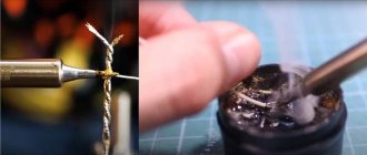
Features of wire tinning
To tin such wires, you need to carefully walk over the soldering area using solder and rosin.
For soldering you will need a massive tip, a large drop of solder and liquid rosin. Flux is applied in the same way, but soldering is a little different. Now the main task is to burn the insulation. This can be done with a large drop of solder. Using longitudinal movements back and forth, apply solder to the soldering area. Insulation burns slowly. There is no need to raise the temperature above 300 °C or use acid. If we can’t tin, then we try again, but instead of rosin we use LTI-120. This flux will help tin the wires no worse than soldering acid.
Starting the soldering station
First start with high voltage part:
- We connect the thermocouple of the hair dryer and the impeller to the main board.
- We connect a 220v incandescent lamp, instead of a hair dryer heater, to a high-voltage socket.
- Turn on the station, start the hair dryer with the “Fen ON” button - the lamp should light up. Turn it off.
- If it doesn’t “bang” and the triac is not hot (it is advisable to attach it to the radiator), we connect the heater of the hair dryer.
- We are launching a hairdryer station. We admire the work of the hairdryer. If there is an extraneous sound (squeaking, grinding) in the triac area, select capacitor C3 in the triac snubber, from 10 to 100 nanofarads. But I’ll be honest and say right away - bet 100n.
- If there is a difference in the temperature readings of the hair dryer, you can correct it with resistor R14 in the op-amp harness.
The simplest installation from the cigarette lighter
The cigarette lighter, which is controlled by 12 volts of the car battery, is capable of creating temperatures that allow soldering BGA controllers and various SMDs.
Many designers believe that such a station provides a heating ring (the so-called “ring”), which will repeat the projection of the heater. However, the test on paper showed absolutely uniform heating, without rings. This means that modifying the cigarette lighter makes sense.
During the test, it was clear that the color of the paper evenly stained the sheet from the center towards the edges. Pure infrared heating plus convection without any blowing - and the cigarette lighter turns into an excellent soldering device.
Soldering stations from the cigarette lighter, compared to soldering hot air guns, are quiet, do not produce any jets or kickbacks, soldering occurs calmly. Ten volts of alternating current, supplied from a suitable transformer, is quite enough to remove a 100-socket processor from the motherboard at a distance of 1-1.5 cm.
The second contact of the spiral must be brought out into the housing tube and fixed with high-temperature sealant. The construction will require brass soldering. It can be done using a gasoline torch, a strip of brass and borax. The distance at which soldering is carried out reaches a maximum of 1.5 cm. This design has proven itself very well.
If you come up with a handle, a body and a holder, and this is quite simple, given the body of the cigarette lighter, then this device will be many times better than a regular Chinese-made soldering iron.
Replacing parts
Some substitutions of active and not so active components:
- Op-amp - Lm358, Lm2904, Ha17358.
- Field-effect transistors - Irfz44, Irfz46, Irfz48, Irf3205, Irf3713 and the like, suitable for voltage and current.
- Bipolar transistor T1 - C9014, C5551, BC546 and the like.
- Optocoupler MOC3021 - MOC3023, MOC3052 without zero crossing (without zero cross according to the datasheet).
- Optocoupler PC817 - PC818, PC123
- Zener diode ZD1 - any for stabilization voltage from 4.3 - 5.1V.
- I used an encoder with a button from a car radio.
- The capacitor in the triac snubber is required for 400v and 100n!
- LCD WH1602 - carefully look at the location of the contacts when connecting to the main board; it may differ from different manufacturers.
- For power supply, the best option would be a stabilized 24V 2-4A power supply from one large eastern store or a converted ATX power supply. Although I used 24V 1.2A from the printer, it gets a little warm when using a soldering iron, but it’s enough for me. At worst, a transformer with a diode bridge, but I don’t recommend it.
Main characteristics of a soldering hair dryer
There are several parameters that you should pay attention to when choosing a hair dryer for soldering - voltage and power. Let the resulting temperature be higher than necessary, it can be adjusted using a relay, wire or distance to the heated surface
In industrial soldering guns, the power reaches 1.7 kW or more
Let the resulting temperature be higher than necessary, it can be adjusted using a relay, wire or distance to the heated surface. In industrial soldering guns, the power reaches 1.7 kW or more.
Recommended voltage range 24-36 Volts. Smaller values will not allow you to achieve the required power, and larger values can be dangerous. Additionally, the voltage will depend on the resistance in the heater wire. It is recommended to use nichrome wire with a resistance of 6 Ohms for a voltage of 24 Volts.
Station body
I have a PC case from a PSU. The panel is made of plexiglass; when painting, it is necessary to leave a window for the screen by gluing masking tape on both sides. The body is painted with one coat of primer and two coats of matte black spray paint. The soldering iron uses a Soviet five-pin plug from a tape recorder. The hair dryer is not disconnected; it is connected directly to the main board with pins. The soldering iron socket, hair dryer cord and power cord are located on the rear wall of the case. The front panel contains only controls, a screen, a power switch and an indicator for the hair dryer. My first design was with a panel made of textolite, with etched inscriptions, but unfortunately there are no photos left. The archive contains drawings of printed circuit boards, a drawing of a panel, a diagram in Splan and firmware.
Safety precautions and rules of use
- It is important to follow fire safety precautions in the workplace.
- During operation, try to prevent sudden changes in the temperature of the heater. Do not touch the heating element or hair dryer attachments.
- Change the attachments after the hair dryer is turned off and cooled down.
- Do not allow liquid to come into contact with the hot air gun.
- Ensure the work area is well ventilated.
A soldering station-hair dryer is a fairly convenient device that you can assemble yourself. Despite its shortcomings, this is a quite suitable device for repairing household appliances.
Soldering stations
List of components
To assemble the printed circuit board and housing, you will need the following components and materials:
- BQ1. Encoder EC12E24204A8
- C1. Electrolytic capacitor 35V, 10uF
- C2, C4-C9. Ceramic capacitors X7R, 0.1uF, 10%, 50V
- C3. Electrolytic capacitor 10V, 47uF
- DD1. Microcontroller ATmega8A-PU in DIP-28 package
- DA1. L7805CV 5V stabilizer in TO-220 package
- DA2. Operational amplifier LM358DT in DIP-8 package
- HG1. Seven-segment three-digit indicator with a common cathode BC56-12GWA. The board also has a seat for a cheap analogue.
- HL1. Any indicator LED for a current of 20 mA with a pin pitch of 2.54 mm
- R2,R7. Resistors 300 Ohm, 0.125W - 2 pcs.
- R6, R8-R20. Resistors 1kOhm, 0.125W - 13pcs
- R3. Resistor 10kOhm, 0.125W
- R5. Resistor 100kOhm, 0.125W
- R1. Resistor 1MOhm, 0.125W
- R4. Trimmer resistor 3296W 100kOhm
- VT1. Field effect transistor IRF3205PBF in TO-220 package
- VT2-VT4. Transistors BC547BTA in TO-92 package - 3 pcs.
- XS1. Terminal for two contacts with pin spacing 5.08 mm
- Terminal for two contacts with pin spacing 3.81 mm
- Terminal for three contacts with pin spacing 3.81 mm
- Radiator for stabilizer FK301
- Housing socket DIP-28
- Housing socket DIP-8
- Soldering iron connector
- Power switch SWR-45 BW(13-KN1-1)
- Soldering iron. We will write about it later
- Plexiglas parts for the body (cutting files at the end of the article)
- Encoder knob. You can buy it, or you can print it on a 3D printer. File for downloading the model at the end of the article
- Screw M3x10 - 2 pcs.
- Screw M3x14 - 4 pcs.
- Screw M3x30 - 4 pcs.
- Nut M3 - 2 pcs.
- M3 square nut – 8 pcs
- M3 washer - 8 pcs
- M3 locking washer – 8 pcs
- Assembly will also require installation wires, zip ties and heat shrink tubing.
This is what a set of all the parts looks like:
Set of parts for assembly of the Simple Solder MK936 soldering station
PCB installation
When assembling a printed circuit board, it is convenient to use the assembly drawing:
Assembly drawing of the printed circuit board of the Simple Solder MK936 soldering station
The installation process will be shown and commented on in detail in the video below. Let us note only a few points. It is necessary to observe the polarity of electrolytic capacitors, LEDs and the direction of installation of microcircuits. Do not install microcircuits until the case is completely assembled and the supply voltage has been checked. ICs and transistors must be handled carefully to avoid damage from static electricity.
Once the board is assembled, it should look like this:
Soldering station printed circuit board assembly