GOST 6357-81 (ST SEV 1157-78) Group G13
STATE STANDARD OF THE USSR Basic norms of interchangeability.Pipe cylindrical thread
Date of introduction 1983-01-01
DEVELOPED by the Ministry of Machine Tool and Tool Industry
PERFORMERS
M.A. Paley, G.S. Kudinova
INTRODUCED by the Ministry of Machine Tool and Tool Industry
Deputy Minister A.E. Prokopovich
APPROVED AND ENTERED INTO EFFECT by Resolution of the USSR State Committee on Standards of December 30, 1981 N 5790
INSTEAD GOST 6357-73
This standard applies to cylindrical pipe threads used in cylindrical threaded connections, as well as in connections of internal cylindrical threads with external conical threads in accordance with GOST 6211-81 and establishes the profile, main dimensions and thread tolerances.
The standard fully complies with ST SEV 1157-78.
MAIN DIMENSIONS
2.1. The designation of the thread size, steps and nominal values of the outer, middle and inner thread diameters must correspond to those indicated in Figure 1 and Table 2.
When choosing sizes, the first row should be preferred to the second.
Table 2 Dimensions in mm
| Thread size designation | Step P | Thread diameters | |||
| Row 1 | Row 2 | d = D | d2 = D2 | d1 = D1 | |
| 1/16 | 0,907 | 7,723 | 7,142 | 6,561 | |
| 1/8 | 9,728 | 9,147 | 8,566 | ||
| 1/4 | 1,337 | 13,157 | 12,301 | 11,445 | |
| 3/8 | 16,662 | 15,806 | 14,950 | ||
| 1/2 | 1,814 | 20,955 | 19,793 | 18,631 | |
| 3/4 | 5/8 7/8 | 22,911 | 21,749 | 20,587 | |
| 26,441 | 25,279 | 24,117 | |||
| 30,201 | 29,039 | 27,877 | |||
| 11¼ | 1⅛ | 2,309 | 33,249 | 31,770 | 30,291 |
| 37,897 | 36,418 | 34,939 | |||
| 41,910 | 40,431 | 38,952 | |||
| 1½ | 1⅜1¾ | 44,323 | 42,844 | 41,365 | |
| 47,803 | 46,324 | 44,845 | |||
| 53,746 | 52,267 | 50,788 | |||
| 22½ | 2¼ | 59,614 | 58,135 | 56,656 | |
| 65,710 | 64,231 | 62,752 | |||
| 75,184 | 73,705 | 72,226 | |||
| 3 | 2¾3¼ | 81,534 | 80,055 | 78,576 | |
| 87,884 | 86,405 | 84,926 | |||
| 93,980 | 92,501 | 91,022 | |||
| 3½4 | 3¾ | 100,330 | 98,851 | 97,372 | |
| 106,680 | 105,201 | 103,722 | |||
| 113,030 | 111,551 | 110,072 | |||
| 56 | 4½5½ | 125,730 | 124,251 | 122,772 | |
| 138,430 | 136,951 | 135,472 | |||
| 151,130 | 149,651 | 148,172 | |||
| 163,830 | 162,351 | 160,872 | |||
2.2. The numerical values of the diameters d2 and d1 are calculated using the following formulas
d2 = D2 = d − 0.640327P (1)
d1 = D1 = d − 1.280654P (2)
The numerical values of the diameter d are established empirically.
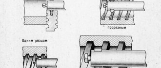
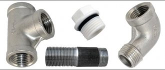
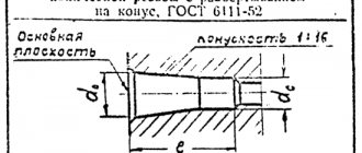
Methods for cutting tapered pipe threads
GOST 24705-81 basic standards of interchangeability.
metric thread. main dimensions Unlike standard cylindrical threads, where the diameter is the same throughout the entire length of the part, conical threads are made taking into account the characteristics of the connection. It is performed on machines that allow the movement of the support at a given angle, or with the help of metalworking tools: dies and taps
When cutting tapered threads, it is important to accurately observe the direction of movement and position of the tool. Control the process using a square
Deviations seriously degrade the quality and the thread can no longer be used in critical connections. The working tool may consist of a set of taps and dies with the numbers indicated on them.
How to cut threads yourself? First of all, it is necessary to securely fix the part in a vice in such a way as to ensure access to the measuring square. If you have a drilling machine, then it is enough to clamp it without distortions. When using a drill, it is more difficult to control the angle. You can use additional devices, for example, a jig or a guide coupling. Particular care should be taken when finishing passes with a conical drill or reamer. An accurately made hole will allow the tap to make the correct entry. When the slope of the outer cone of the part corresponds to the specified angle, the die will easily self-orient along it and the thread will be of high quality.
Slicing equipment
In practice, an ordinary mechanic does not often have to make a conical thread, if the specifics of production are not related to the manufacture of parts with this type of connection. A home master encounters this operation even less often. A table for determining diameters will be an assistant in your work.
| Size in inches | Hole diameter, mm | Drilling depth, mm | |
| dc | do | ||
| ⅛ | 8,10 | 8,57 | 15 |
| ¼ | 10,80 | 11,45 | 20 |
| ⅜ | 14,30 | 14,95 | 24 |
| ½ | 17,90 | 18,63 | 29 |
| ¾ | 23,35 | 24,12 | 31 |
| 1 | 29,35 | 30,29 | 37 |
| 1¼ | 37,80 | 38,95 | 40 |
| 1½ | 43,70 | 44,85 | 42 |
| 2 | 55,25 | 56,66 | 44 |
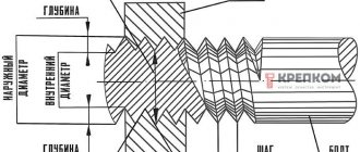
The largest diameter of the cone is denoted by do, and the smallest by dc. To facilitate the entry of the tool, a chamfer is made. It is difficult and time-consuming to make a tap in a cylindrical hole. To reduce labor intensity and speed up the operation, use conical drills and reamers of the required size. If the tool is complete, then first take a tap or die with number 1. This is rough cutting. Then they pass with tool No. 2. Sometimes a set may contain 3 types of taps. In non-ferrous metals, tapered threads can be made in one pass if cutting fluids are used. When working with steel, it is advisable to go through the hole sequentially with all taps.
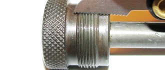
You can also see the cone from the jaws for internal measurements. It is enough to insert them inside and you will see the slope on the die relative to the parallel jaws of the caliper. Conical dies are wider than regular dies because they must completely cover the length of the workpiece. They are harder to work with. The load is distributed over the entire cutting surface, so use a powerful wrench with long handles, or extend them to create a lever. Designated machine die 2684-0015, manual 2684-0015r. All characteristics are specified in GOST 6228-80. The tap has the abbreviation 2680-0016. Technical characteristics are described in GOST 6227-80.
Conical connections are used in critical components, so the requirements for surface finish are high. This can only be achieved by using high-quality cutting fluids. The choice of compositions is wide. But if professional materials are not at hand, then at home you can use animal fat for work. According to its characteristics, it is excellent for this purpose. Many experienced masters often use it in their practice. It guarantees good glide and high-quality cutting of metal without chipping.
The cutting tool is made of tool, high-speed steels. GOST specifies the recommended service life of dies and taps. It is calculated for a tool made of R6M5 alloy using workpieces made of steel 45. The die must be guaranteed to process from 125 (more than 1 inch) to 225 (less than an inch) external threads that meet the requirements of GOST. Accordingly, if more durable alloys of parts are used in the work, the service life decreases. To check the quality of processing, geometric dimensions and compliance with the profile, special templates are used - calibers. The same devices are used when sharpening cutters for lathes.
TOLERANCES
3.1. Schemes of tolerance fields for external and internal threads are shown in Figure 2.
es is the upper deviation of the external thread diameters;
ES - upper deviation of internal thread diameters;
ei is the lower deviation of the external thread diameters;
EI - lower deviation of internal thread diameters;
— diameter tolerances d, d2, D1, D2
Damn.2
Deviations are counted from the nominal thread profile in the direction perpendicular to the thread axis.
3.2. Tolerances for the average thread diameter establish two accuracy classes - A and B.
Tolerances for the average thread diameter are cumulative.
Diameter tolerances d1 and D are not established.
3.3. The numerical values of the tolerances for the diameters of external and internal threads must correspond to those given in Table 3.
Table 3
| Thread size designation | Pitch P, mm | External thread | Internal thread | ||||
| Thread diameters | |||||||
| d | d2 | D2 | D1 | ||||
| Tolerances, microns | |||||||
| Td | Td2 | TD2 | TD1 | ||||
| Class A | Class B | Class A | Class B | ||||
| 1/16 | 0,907 | 214 | 107 | 214 | 107 | 214 | 282 |
| 1/8 | 214 | 107 | 214 | 107 | 214 | 282 | |
| 1/4 | 1,337 | 250 | 125 | 250 | 125 | 250 | 445 |
| 3/8 | 250 | 125 | 250 | 125 | 250 | 445 | |
| 1/2 | 142 | 284 | 142 | 284 | 541 | ||
| 5/8 | 1,814 | 284 | 142 | 284 | 142 | 284 | 541 |
| 3/4 | 284 | 142 | 284 | 142 | 284 | 541 | |
| 7/8 | 284 | 142 | 284 | 142 | 284 | 541 | |
| 360 | 360 | 360 | 640 | ||||
| 1⅛ | 2,309 | 360 | 180 | 360 | 180 | 360 | 640 |
| 1¼ | 360 | 180 | 360 | 180 | 360 | 640 | |
| 1⅜ | 2,309 | 180 | 360 | 180 | 360 | ||
| 1½ | 360 | 180 | 360 | 180 | 360 | 640 | |
| 1¾ | 360 | 180 | 360 | 180 | 360 | 640 | |
| 2 | 360 | 180 | 360 | 180 | 360 | 640 | |
| 2¼ | 217 | 434 | |||||
| 2½ | 434 | 217 | 434 | 217 | 434 | 640 | |
| 2¾ | 434 | 217 | 434 | 217 | 434 | 640 | |
| 3 | 434 | 434 | 217 | 640 | |||
| 3¼ | 434 | 217 | 434 | 217 | 434 | 640 | |
| 3½ | 434 | 217 | 434 | 217 | 434 | 640 | |
| 3¾ | 434 | ||||||
| 4 | 434 | 217 | 434 | 217 | 434 | 640 | |
| 4½ | 434 | 217 | 434 | 217 | 434 | 640 | |
| 5 | 434 | 640 | |||||
| 5½ | 434 | 217 | 434 | 217 | 434 | 640 | |
| 6 | 434 | 217 | 434 | 217 | 434 | 640 | |
Note. The numerical values of the tolerances are established empirically.
3.4. Make-up lengths are divided into two groups: normal N and long L.
Make-up lengths related to groups N and L are given in Table 4.
Table 4 Dimensions in mm
| Thread size designation | Step P | Make-up length | |
| N | L | ||
| 1/16 | 0,907 | St. 4 to 12 | St. 12 |
| 1,337 | St. 5 to 16 | St. 16 | |
| 1,814 | St. 7 to 22 | St. 22 | |
| 1⅛ | 2,309 | St. 10 to 30 | St. 30 |
| 1¼ | |||
| 1⅜ | |||
| 1½ | 2,309 | St. 12 to 36 | St. 36 |
| 1¾ | |||
| 2 | |||
| 2¼ | |||
| 2½ | |||
| 2¾ | |||
| 3 | |||
| 3¼ | 2,309 | St. 13 to 40 | St. 40 |
| 3½ | |||
| 3¾ | |||
| 4 | |||
| 4½ | |||
| 5 | |||
| 5½ | |||
Note. Numerical values of make-up lengths are established empirically.
3.5. The thread tolerance, unless otherwise stated, refers to the longest normal make-up length N specified in Table 4, or to the entire thread length if it is less than the longest normal make-up length.
3.6. The tolerances of the average diameter of the internal thread according to this standard, intended for connection with an external tapered thread in accordance with GOST 6211-81, must correspond to accuracy class A.
In this case, the design of parts with internal cylindrical threads must ensure screwing in of external conical threads to a depth not less than specified in GOST 6211-81.
3.7. The numerical values of the maximum deviations of the diameters of the external and internal threads must correspond to those indicated in Table 5.
Table 5
| Thread size designation | Pitch P, mm | External thread | Internal thread | ||||||||||
| Thread diameters | |||||||||||||
| d | d2 | d1 | D | D2 | D1 | ||||||||
| Limit deviations, µm | |||||||||||||
| es | ei | es | ei | es | EI | ES | EI | ES | EI | ||||
| Class A | Class B | Class A | Class B | ||||||||||
| 1/16 | 0,907 | -214 | -107 | -214 | +107 | +214 | +282 | ||||||
| 1/8 | 0 | — 214 | 0 | -107 | -214 | 0 | 0 | +107 | +214 | 0 | +282 | 0 | |
| 1/4 | 1,337 | — 250 | — 125 | -250 | +125 | +250 | +445 | ||||||
| 3/8 | 0 | -250 | 0 | -125 | -250 | 0 | 0 | +125 | +250 | 0 | +445 | 0 | |
| 1/2 | 0 | — 284 | 0 | -142 | -284 | 0 | 0 | +142 | +284 | 0 | +541 | 0 | |
| 5/8 | 1,814 | 0 | -284 | 0 | -142 | -284 | 0 | 0 | +142 | +284 | 0 | +541 | 0 |
| 3/4 | 0 | -284 | 0 | -142 | -284 | 0 | 0 | +142 | +284 | 0 | +541 | 0 | |
| 7/8 | 0 | -284 | 0 | -142 | -284 | 0 | 0 | +142 | +284 | 0 | +541 | 0 | |
| 1 | -360 | -180 | -360 | 0 | 0 | +180 | +360 | 0 | +640 | 0 | |||
| 1⅛ | 0 | -360 | 0 | -180 | -360 | 0 | 0 | +180 | +360 | 0 | +640 | 0 | |
| 1¼ | 0 | -360 | 0 | -180 | -360 | 0 | 0 | +180 | +360 | 0 | +640 | 0 | |
| 1⅜ | 0 | -360 | 0 | -180 | -360 | 0 | 0 | +180 | +360 | 0 | +640 | 0 | |
| 1½ | 2,309 | 0 | -360 | 0 | -180 | -360 | 0 | 0 | +180 | +360 | 0 | +640 | 0 |
| 1¾ | 0 | -360 | 0 | -180 | -360 | 0 | 0 | +180 | +360 | 0 | +640 | 0 | |
| 2 | 0 | -360 | 0 | -180 | -360 | 0 | 0 | +180 | +360 | 0 | +640 | 0 | |
| 2¼ | 0 | -434 | 0 | -217 | -434 | 0 | 0 | +217 | +434 | 0 | +640 | 0 | |
| 2½ | 0 | — 434 | 0 | -217 | -434 | 0 | 0 | +217 | +434 | 0 | +640 | 0 | |
| 2¾ | -434 | 0 | -217 | -434 | +217 | +434 | +640 | 0 | |||||
| 3 | 0 | -434 | 0 | -217 | -434 | 0 | 0 | +217 | +434 | 0 | +640 | 0 | |
| 3¼ | 0 | -434 | 0 | -217 | -434 | 0 | 0 | +217 | +434 | 0 | +640 | 0 | |
| 3½ | 0 | -434 | 0 | -217 | -434 | 0 | 0 | +217 | +434 | 0 | +640 | 0 | |
| 3¾ | 0 | -434 | 0 | -217 | -434 | 0 | 0 | +217 | +434 | 0 | +640 | 0 | |
| 4 | 2,309 | 0 | -434 | 0 | -217 | -434 | 0 | 0 | +217 | +434 | 0 | +640 | 0 |
| 4½ | 0 | -434 | 0 | -217 | -434 | 0 | 0 | +217 | +434 | 0 | +640 | 0 | |
| 5 | 0 | -434 | 0 | -217 | -434 | 0 | 0 | +217 | +434 | 0 | +640 | 0 | |
| 5½ | 0 | -434 | 0 | -217 | -434 | 0 | 0 | +217 | +434 | 0 | +640 | 0 | |
| 6 | 0 | -434 | 0 | -217 | -434 | 0 | 0 | +217 | +434 | 0 | +640 | 0 | |
Note. The lower deviation of the inner diameter d1 and the upper deviation of the outer diameter D are not set.
3.8. The maximum deviations for cutting the tops and bottoms of external and internal threads are given in the reference appendix.
GOST 6357-81 Basic standards of interchangeability. Cylindrical pipe thread
- TPA Directory
- GOST and standards for pipeline fittings
- GOST 6357-81 Basic standards of interchangeability. Cylindrical pipe thread GOST 6357-81 Basic standards of interchangeability. Cylindrical pipe thread
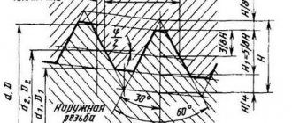
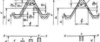
GOST 6357-81 Basic standards of interchangeability. Cylindrical pipe thread GOST 6357-81 Basic standards of interchangeability. Cylindrical pipe thread 1. PROFILE 1.1. The nominal thread profile and the dimensions of its elements must correspond to those indicated in the drawing. 1 and in table. 1. Damn. 1. Dimensions in mm
d is the outer diameter of the external thread (pipe); d1 - internal diameter of the external thread; d2 - average diameter of external thread; D—outer diameter of the internal thread (coupling); D1 - internal diameter of the internal thread; D2 - average diameter of internal thread; P - thread pitch; H is the height of the original triangle; H1 - working height of the profile; R - radius of curvature of the top and bottom of the thread
Table 1. Dimensions in mm
| Step P | Number of steps z at a length of 25.4 mm | H=0.960491P | H1=0.640327 P | H/6 = 0.160082 P | R = 0.137329 P |
| 0.907 1,337 1,814 2,309 | 28 19 14 11 | 0,871165 1,284176 1,742331 2,217774 | 0.580777 0,856117 1,161553 1,478515 | 0,145194 0,214029 0,290389 0,369629 | 0,124557 0,183609 0,249115 0,317093 |
Note. The numerical values of the steps are determined from the ratio P = 25.4/z, rounded to the 3rd decimal place and taken as the initial ones when calculating the main elements of profile 1.2. The tops of external threads, as well as internal threads, can be made with a flat cut in cases where the possibility of connecting it with an external tapered thread in accordance with GOST 6211-81 is excluded. 2. MAIN DIMENSIONS 2.3. The designation of the thread size, pitches and nominal values of the outer, middle and inner thread diameters must correspond to those indicated in the drawing.
1 and in table. 2. When choosing sizes, the first row should be preferred to the second. Table 2. Dimensions in mm
| Thread size designation | Step P | Thread diameters | |||
| Row 1 | Row 2 | d=D | d2=D2 | d1=D1 | |
| 1/16 1/8 | 0,907 | 7.723 9,728 | 7,142 9,147 | 6,561 8,566 | |
| 1/4 3/8 | 1,337 | 13,157 16,662 | 12,301 15,806 | 11,445 14,950 | |
| 1/2 | 1,814 | 20,955 | 19,793 | 18,631 | |
| 3/4 | 5/8 7/8 | 22,911 26,441 30,201 | 25.749 25.279 29.0З9 | 20,587 24,117 27,877 | |
| 1 1 1/2 | 1 1/8 | 2,309 | 33,249 33,891 41,910 | 31,770 36,418 40,431 | 30,291 34,939 38,952 |
| 1 1/2 | 1 3/8 1 3/4 | 44,323 47,803 53,746 | 42,844 46,324 52,267 | 41,365 44,845 50,788 | |
| 2 2 1/2 | 2 1/4 | 59,614 65,710 75,184 | 58,135 64,231 73,705 | 56,656 62,762 72,226 | |
| 3 | 2 3/4 3 1/4 | 81,534 87,884 93,980 | 80,055 86,405 92,501 | 78,576 84,926 91,022 | |
| 3 1/2 4 | 3 3/4 | 100,330 106,680 113,030 | 98,851 105,201 111,551 | 97,372 103,722 110,072 | |
| 5 6 | 4 1/2 5 1/2 | 125,730 138,430 151,130 163,830 | 124,251 136,951 148,651 162,351 | 122,772 135,472 148,172 160,872 | |
2.2. The numerical values of the diameters d2 and d1 are calculated using the following formulas. d2 = D2 = d - 0.640327 P (1) d1 = D1 = d - 1.280654 P (2) The numerical values of the diameter d are established empirically. 3. TOLERANCES 3.1. Schemes of tolerance fields for external and internal threads are shown in Fig. 2. Deviations are counted from the nominal thread profile in the direction perpendicular to the thread axis. 3.2. Tolerances for the average thread diameter establish two accuracy classes - A and B.
Damn. 2
es is the upper deviation of the external thread diameters;
ES - upper deviation of internal thread diameters; ei is the lower deviation of the external thread diameters; EI - lower deviation of internal thread diameters; Td, Td2, TD1, TD2 - tolerances of diameters d, d1, D1, D2. Tolerances for the average thread diameter are cumulative. Tolerances for diameters d1 and D are not established. 3.3. The numerical values of the tolerances for the diameters of external and internal threads must correspond to those given in table.
3. Table 3
| Thread size designation | Pitch P, mm | External thread | Internal thread | ||||
| Thread diameters | |||||||
| d | d2 | D2 | D1 | ||||
| Tolerances, microns | |||||||
| Td | Td2 | TD2 | TD1 | ||||
| Class A | Class B | Class A | Class B | ||||
| 1/16 1/8 | 0,907 | 214 214 | 107 107 | 214 214 | 107 107 | 214 214 | 282 282 |
| 1/4 3/8 | 1,337 | 250 250 | 125 125 | 250 250 | 125 125 | 250 250 | 445 445 |
| 1/2 5/8 3/4 7/8 | 1,814 | 284 284 284 284 | 142 142 142 142 | 284 284 284 284 | 142 142 142 142 | 284 284 284 284 | 541 541 541 541 |
| 1 1 1/3 1 1/4 | 2,309 | 360 360 360 | 180 180 180 | 360 360 360 | 180 180 180 | 360 360 360 | 640 640 640 |
| 1 1 3/8 1 1/2 2 3/4 | 2,309 | 360 360 360 360 | 180 180 180 180 | 360 360 360 360 | 180 180 180 180 | 360 360 360 360 | 640 640 640 640 |
| 2 1/4 2 1/2 2 3/4 | 434 434 434 | 217 217 217 | 434 434 434 | 217 217 217 | 434 434 434 | 640 640 640 | |
| 3 3 1/4 3 1/2 | 434 434 434 | 217 217 217 | 434 434 434 | 217 214 217 | 434 434 434 | 640 640 640 | |
| 3 3/4 4 4 1/2 | 434 434 434 | 217 217 217 | 434 434 434 | 217 217 217 | 434 434 434 | 640 640 640 | |
| 5 5 1/2 6 | 434 434 434 | 217 217 217 | 434 434 434 | 217 217 217 | 434 434 434 | 640 640 640 | |
Note. The numerical values of the tolerances are established empirically. 3.4. Make-up lengths are divided into two groups: normal N and long L. Make-up lengths belonging to groups N and L are given in table.
4. Table 4. Dimensions in mm
| Thread size designation | Step P | Make-up length | Thread size designation | Step P | Make-up length | ||
| N | L | N | L | ||||
| 1/16 1/8 | 0,907 | St. 4 to 12 | St. 12 | 2 2 1/4 2 1/2 2 3/4 3 | 2,309 | St. 12 to 36 | St. 36 |
| 1/4 3/8 | 1,337 | St. 5 to 16 | St. 16 | ||||
| 1/2 5/8 Z/4 7/8 | 1,814 | St. 7 to 22 | St. 22 | 3 1/4 3 1/2 3 3/4 4 4 1/2 5 5 1/2 6 | 2,309 | St. 13 to 40 | St. 40 |
| 1 1 1/3 1 1/4 1 3/8 | 2,309 | St. 10 to 30 | St. 30 | ||||
| 1 1/2 1 3/4 | 2,309 | Sat 12 to 36 | St. 36 | ||||
Note. Numerical values of make-up lengths are established empirically. 3.5. The thread tolerance, unless otherwise stated, refers to the largest normal make-up length N indicated in Table. 4, or to the entire thread length if it is less than the longest normal make-up length. 3.6. Tolerances of the average diameter of the internal thread according to this standard, intended for connection with an external conical thread in accordance with GOST 6211-81, must correspond to accuracy class A. In this case, the design of parts with internal cylindrical threads must ensure screwing in the external conical thread to a depth not less than specified in GOST 6211- 81. 3.7. The numerical values of the maximum deviations of the diameters of the external and internal threads must correspond to those indicated in the table. 5. 3.8. The maximum deviations for cutting the tops and bottoms of external and internal threads are given in the reference appendix.
Table 5
| Thread size designation | Pitch P, mm | External thread | Internal thread | ||||||||||
| Thread diameters | |||||||||||||
| d | d2 | d1 | D | D2 | D1 | ||||||||
| Limit deviations, µm | |||||||||||||
| es | ei | es | ei | es | EI | ES | EI | ES | EI | ||||
| Class A | Class B | Class A | Class B | ||||||||||
| 1/16 1/8 | 0,907 | 0 0 | -214 -214 | 0 0 | -107 -107 | -214 -214 | 0 0 | 0 0 | +107 +107 | +214 +214 | 0 0 | +282 +282 | 0 0 |
| 1/4 3/8 | 1,337 | 0 0 | -250 -250 | 0 0 | -125 -125 | -250 -250 | 0 0 | 0 0 | +125 +125 | +250 +250 | 0 0 | +445 +445 | 0 0 |
| 1/2 5/8 3/4 7/8 | 1,814 | 0 0 0 0 | -284 -284 -284 -284 | 0 0 0 0 | -142 -142 -142 -142 | -284 -284 -284 -284 | 0 0 0 0 | 0 0 0 0 | +142 +142 +142 +142 | +284 +284 +284 +284 | 0 0 0 0 | +541 +541 +541 +541 | 0 0 0 0 |
| 1 1 1/8 1 1/4 1 3/8 | 2,309 | 0 0 0 0 | -360 -360 -360 -360 | 0 0 0 0 | -180 -180 -180 -180 | -360 -360 -360 -360 | 0 0 0 0 | 0 0 0 0 | +180 +180 +180 +180 | +360 +360 +360 +360 | 0 0 0 0 | +640 +640 +640 +640 | 0 0 0 0 |
| 1 1/2 1 3/4 2 2 1/4 2 1/2 | 0 0 0 0 0 | -360 -360 -360 -434 -434 | 0 0 0 0 0 | -180 -180 -180 -217 -217 | -360 -360 -360 -434 -434 | 0 0 0 0 0 | 0 0 0 0 0 | +180 +180 +180 +217 +217 | +360 +360 +360 +434 +434 | 0 0 0 0 0 | +640 +640 +640 +640 +640 | 0 0 0 0 0 | |
| 2 3/4 3 3 1/4 3 1/2 3 3/4 4 4 1/2 5 5 1/2 6 | 2,309 | 0 0 0 0 0 0 0 0 0 0 | -434 -434 -434 -434 -434 -434 -434 -434 -434 -434 | 0 0 0 0 0 0 0 0 0 0 | -217 -217 -217 -217 -217 -217 -217 -217 -217 -217 | -434 -434 -434 -434 -434 -434 -434 -434 -434 -434 | 0 0 0 0 0 0 0 0 0 0 | 0 0 0 0 0 0 0 0 0 0 | +217 +217 +217 +217 +217 +217 +217 +217 +217 +217 | +434 +434 +434 +434 +434 +434 +434 +434 +434 +434 | 0 0 0 0 0 0 0 0 0 0 | +640 +640 +640 +640 +640 +640 +640 +640 +640 +640 | 0 0 0 0 0 0 0 0 0 0 |
Note. The lower deviation of the inner diameter d1 and the upper deviation of the outer diameter D are not set. 4. THREAD DESIGNATIONS 4.1. The symbol for a cylindrical pipe thread must include: the letter G, the designation of the thread size and the accuracy class of the average diameter. The symbol for left-hand threads is supplemented with the letters LH. Examples of thread symbols: accuracy class A: G 1 1/2 - A left-hand thread, accuracy class B: G1 1/2 LH - B 4.2. The make-up length N is not indicated in the thread designation. The make-up length L is indicated in millimeters. Example: G1 1/2 LH - B - 40 (40 is make-up length) 4.3. The fit is indicated by a fraction, the numerator of which indicates the designation of the accuracy class of the internal thread, and the denominator indicates the designation of the accuracy class of the external thread. Example: G1 1/2 - A/A or G1 1/2 LH - A/B 4.4. The connection of an internal pipe cylindrical thread of accuracy class A according to this standard with an external pipe-conical thread in accordance with GOST 6211-81 is designated as follows: Example: G/R 1 1/2 - A APPENDIX Reference LIMITED DEVIATIONS FOR THE CUT OF THE TOP AND FOOT THREAD 1. This appendix contains information about the maximum deviations of a cut of size H/6 of the tops and bottoms of external and internal threads, which are the initial ones when designing a thread-forming tool and are not subject to mandatory control, unless specifically stated. 2. Maximum size deviations are shown in the drawing and table.
Damn 3
eS—upper deviation of the cut of the top and bottom of the external thread; ES—upper deviation of the cut of the top and bottom of the internal thread; ei—lower deviation of the cut of the top and bottom of the external thread; EI—lower deviation of the cut of the top and bottom of the internal thread
Pipe fittings portal Armtorg.ru
Barnaul, Zavodskoy 9th passage, 5g/8.
+7 (3852) 567-734; +7 (3852) 226-927
Share
Previous article Next article
← return to the section GOST and standards for pipeline fittings ← return to the table of contents of the directory
Latest registered companies (Register
Russia, St. Petersburg
NPP TrubTehArmatura
Russia, Sverdlovsk region
LLC PC "Megapolis"
Russia, Sverdlovsk region Product cloud
.Other...2068 Safety valve blocks146 Bronze valves137 Steel valves949 Cast iron valves570 Energy valves144 Stainless steel valves370 Steel valves2163 Steel valves - HL371 Cast iron valves1102 Energy valves86 Steel valves294 Cast iron valves33 5 Test equipment for injection molding machines119 Check valves974 Shut-off valves61 Safety valves1120 Control valves560 Energy valves128 Bellows compensators203 Steel condensate drains55 Cast iron condensate drains67 Boiler equipment220 Bronze taps149 Stainless steel taps179 Steel taps608 Steel taps - HL87 Cast iron taps149 Pressure gauges88 Hardware433 Pumps246 Bends1081 Heating equipment96 Switching devices46 Transitions461 Fire fittings48 Radiators33 Control fittings34 1 Repair equipment for injection molding machines53 Water meters159 Thermometers47 Tees492 Pipes702 Level indicators71 Sealing materials67 Filters, strainers410 Fittings206 Flanges2400 Ball valves1244 Electric drives251
THREAD DESIGNATIONS
4.1. The symbol for a cylindrical pipe thread should include:
letter G, designation of thread size and accuracy class of average diameter. The symbol for left-hand threads is supplemented with the letters LH.
Examples of thread symbols:
accuracy class A: G1½ − A
left-hand thread accuracy class B: G1½LH − B
4.2. The make-up length N is not indicated in the thread designation.
The make-up length L is indicated in millimeters.
4.3. The fit is indicated by a fraction, the numerator of which indicates the designation of the accuracy class of the internal thread, and the denominator indicates the designation of the accuracy class of the external thread.
Example: G1½ − A/A
G1½LH − A/B
4.4. The connection of an internal pipe cylindrical thread of accuracy class A according to this standard with an external pipe conical thread in accordance with GOST 6211-81 is designated as follows:
Example:
G/R 1½ − A or G/R 1½ − A
PROFILE
1.1. The nominal thread profile and the dimensions of its elements must correspond to those indicated in Figure 1 and Table 1.
— outer diameter of the external thread (pipe); — internal diameter of the external thread; - average diameter of external thread; — outer diameter of the internal thread (coupling); — internal diameter of the internal thread; — average diameter of the internal thread; — thread pitch; — height of the original triangle; — working height of the profile; - radius of curvature of the top and bottom of the thread
Damn.1
Table 1
Dimensions in millimeters
| Step | Number of steps per length 25.4 mm | ||||
| 0,907 | 28 | 0,871165 | 0,580777 | 0,145194 | 0,124557 |
| 1,337 | 19 | 1,284176 | 0,856117 | 0,214029 | 0,183609 |
| 1,814 | 14 | 1,742331 | 1,161553 | 0,290389 | 0,249115 |
| 2,309 | 11 | 2,217774 | 1,478515 | 0,369629 | 0,317093 |
Note. The numerical values of the steps are determined from the ratio with rounding to the third decimal place and taken as the initial ones when calculating the main elements of the profile.
1.2. The tops of external threads, as well as internal threads, can be made with a flat cut in cases where the possibility of connecting it with an external tapered thread in accordance with GOST 6211 is excluded.
Parameters of tapered pipe thread
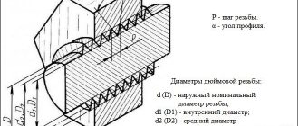
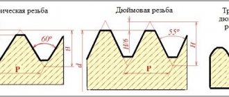
This type of connection is indicated exclusively in inches. Values are indicated in whole and fractional parts. The profile of a tapered pipe thread differs from its standard inch counterpart. The apex angle is 55° in the first case and 60° in the second. In some cases, connections of both types are allowed. The conditions are defined in GOST 6211–81. § 4.7 says that in this case it is possible to use an external conical pipe thread in conjunction with a cylindrical internal thread. The nominal values must match. For example, the diameter of 1½ should be the same for both parts. The internal pipe inch tapered thread is not connected to the external cylindrical element.
This parameter is the same for all types of tapered pipe threads, but the pitch is significantly different. Historically, it has been measured in threads per inch. But in the process of production evolution, some values do not correspond to the specified data. Therefore, all inch threads today are deciphered in the usual European standards. The metric measurement system is much more convenient to use.
Below are the correspondence between inch values and analogues in mm:
- ⅛ - 28 (number of threads per inch), 0.907 mm;
- ¼ - 19, 1.337 mm;
- ⅜ - 19, 1.337 mm;
- ½ - 14, 18.14 mm
- ¾ - 14, 18.14 mm
- 1 - 11, 23.09 mm
- 1¼ - 11, 23.09 mm
- 1½ - 11, 23.09 mm
- 2 - 11, 23.09 mm
Tapered pipe threads have three diameters: external, internal and middle. The connection drawing is made in the form of a trapezoid. Its base is external thread, the top is internal. The average is calculated mathematically. It roughly corresponds to the dimensions of a regular cylindrical inch thread.
This is important to know when combining different types of connections. That is, when a conical part is screwed into a regular inch thread, then at the beginning of rotation the connection is loosened
Towards the middle of the length it becomes denser, further movement is carried out with increasing tension. Advantages of a cone is often used in standard connections with loose internal threads. If the part is worn out and the internal hole becomes larger than normal, then the cylindrical element can be replaced. The angle of the cone compensates for the slackness along the diameter.
You should know that when preparing parts for processing, allowances must be taken into account. When making a cone on the incoming part, they are guided by the outer diameter value according to the table. Then they check the length of the workpiece and only then make the required slope. On a lathe, the angle is set on the upper carriage of the support. The second option is to use a shaped cutter. In both cases, you will have to do manual adjustment, and it is difficult to accurately align the cutting tool, so be sure to check the angle with a special gauge.
The profile apex angle of 55° was not chosen by chance. This guarantees better sealing of the connection. When tightening, the parts grind together with slight creasing of the profile. However, using force during assembly is not recommended. The taper of the parts causes the load vector to be directed outward. The part may simply break due to excessive force. Especially if the thickness of the element with internal thread is small. It is not recommended to use the technology on thin-walled brass and aluminum parts. This must be remembered when it is decided to combine conical pipe and cylindrical pipe threads, which were not calculated during production for this type of load.
Slicing principles
GOST 24705-2004 (ISO 724:1993) basic standards of interchangeability. metric thread. main dimensions
When slicing, you need to take into account a number of features:
- cutting accuracy is determined by the parameters of the holes: diameter, perpendicularity of the center line to the surface of the workpiece, length;
- inch is cut with a profile angle of 60 degrees, and metric - 55;
- the tops and bottoms of inch threads, unlike metric threads, have more bluntness and have better tightness;
- to simplify the process, drilling a hole with a cylindrical drill is required; it is selected according to the smallest diameter;
- chamfering is required;
- When working, the tool must be lubricated to prevent overheating;
- when cutting, 2 turns are made forward, and then 1 turn back;
- the force on the cutting tool can be weakened after driving to the middle of the calculated length;
- Once the desired length is reached, the die can be removed by rotating in the opposite direction;
- Before finishing cutting, you need to do a rough cut.
Conical taps are distinguished by an elongated shape of the intake part and an incomplete thread, which additionally plays a calibrating role. In the upper part they have a square cross-section; longitudinal grooves are made on the cutting part to remove chips.
Cutting:
- The workpiece is vertically fixed in a vice.
- Lubricant is applied to the tool.
- The tool is applied perpendicular to the center line for cutting threads, that is, strictly in a horizontal plane.
- Several turns are cut.
- The correctness of the work is checked. In case of misalignment, you need to remove the cutting tool, tap the part and repeat steps 3–4.
- Further cutting is carried out provided that the first turns are correctly positioned. You can check with a regular level.
- A thread is formed to the required length.
- At the end of the work, remove the chips and clean the tool from lubricant.
For cutting on lathes, heads with thread-cutting dies are used. A special design feature of the tool is the automatic spreading of the dies during operation. This ensures high machining precision and optimal productivity.
In some cases, knurling rollers are used. The cutting accuracy is lower than when using heads, and the complexity of the work is higher.
To set up a lathe, it is enough to set the spindle rotation speed to low and associate the caliper offset with it. Setting rule: one revolution of the spindle must correspond to the movement of the caliper by the distance of the thread pitch.
On lathes, adjustments are easy because there are many clutch combinations available on the gearbox. If necessary, it is possible to cut threaded grooves of non-standard sizes.