Add a link to a discussion of the article on the forum
RadioKot >Schemes >Power >Chargers >
| Article tags: | Add a tag |
The evolution of pulse chargers for car batteries based on AT/ATX.
Author: Provada Yuri Petrovich aka Simurg Published 08/31/2010
2010
In the operating instructions for the first domestic cars it was written that the battery cannot be used in the summer (start the car and drive) with a charge of less than 50%, and in winter with less than 75%. Let's analyze why the battery in some cases will not have time to fully charge. For example, it’s winter outside, you need to go to 3-4 places in a day, it’s -25 outside, the engine cools down after 15 minutes, and the breaks between trips are 1-3 hours. It's already dark and you use the headlights, as well as heated seats and windows. As a result, this whole thing consumes at least 400-500 watts. The generator produces 800 watts and you have 300 watts (in theory) left to charge the battery. 300 watts at 14 V in the car’s on-board network is approximately 20 A. So, a completely discharged battery with a capacity of, for example, 52 Ah, even in theory, can be fully charged in no faster than 3.5 hours (70 Ah chemical capacity 3.5 hours * 20 A). But in reality, the charging current will never reach 20 A; in the first minutes, charging will occur with a current of 10-15A, and then 3-5A. As a result, the battery does not have time to charge on the way to the nearest parking lot. Of course, it is not completely discharged. Let's calculate how much it is discharged by the starter in winter. At a temperature of -25, the total operating time of the starter will be from 30 seconds to 5 minutes, for example, your starter worked for a total of 3 minutes per day. The starter consumes an average of 250A at this engine temperature (at start-up it can be 900A), while in 3 minutes it consumes 360 hours * 250A = 12.5 Ah. Is this a lot or a little? As noted above, a battery has a chemical capacity and a useful capacity. Chemical is the one that is stored in a chemical reaction, and useful is the one that is spent on the load. Naturally, part of the energy during discharge in the form of heat is lost on the battery itself and the useful capacity depends on the load and temperature. For example, if you discharge a battery for 10 hours at +25 degrees, its capacity becomes 52 Ah (and the chemical capacity is about 70), if you discharge it in an hour in the heat, its capacity drops to 35 Ah, the remaining 35, from the chemical capacity, goes to heating the battery itself . If the discharge occurs at -25, then the electrolyte resistance increases, and even more heat is lost from the battery itself. The actual capacity in the cold can be 60% of the nominal, i.e. in starter mode 35 * 0.6 = 21 Ah. So how much is 12.5 Ah spent on starting the starter in a day? In this situation, the most unpleasant thing is that the chemical capacity does not change. And in order to charge the battery, you need to spend 70 Ah in any situation. We turned the starter for 3 minutes, spent 12.5 Ah (60% of the capacity), and will have to return 40 Ah. If you don’t drive 4 hours to the garage, don’t stand with the engine running in cold weather for hours in traffic jams, then your generator is not able to provide a full charge to the battery, so it needs to be recharged periodically.
The final charge voltage at a temperature of 20 degrees Celsius is 2.25-2.3 volts per battery cell. For a battery with a nominal voltage of 12 V (6 cells), the final charge voltage is 13.5-13.8 V. If the battery is operated at other temperatures, then to increase the battery life it is recommended to reduce the final charge voltage to 2.2-2.25 V/cell at a temperature of 40 degrees and increase voltage up to 2.35-2.4 V at a temperature of 0 degrees. The use of such temperature compensation of the charging voltage allows you to increase the battery life at 40 degrees Celsius by 15%. But in order for the battery to charge, the output voltage of the charger must be raised at least one volt above the maximum voltage of the charged battery (voltage approximately 15.8 volts). To fully charge a depleted battery, it is recommended to charge it for 24 hours. If a faster (within 8-10 hours) battery charge is required in the case of cyclic operation, the final charge voltage is increased to 2.4-2.48 V/el (at 20 degrees Celsius) and the charging time must be limited in accordance with the remaining charge of the battery before charging . It should be noted that the electrochemical polarization potential of lead drops to zero at approximately 65C, and the battery cannot exist above this temperature, i.e. it will be impossible to charge it, since the “-” will only undergo a side reaction, in which only hydrogen will be reduced, and the lead itself will begin to react with sulfuric acid. Applying an EMF voltage of 2V to the battery while charging + an electrochemical polarization potential of 1.3V (approximately 3.3V per cell) also leads to a complete shift of the process to side reactions. During operation, to minimize by-product gas formation and the rate of corrosion of the positive plates, the applied voltage to the element should not be higher than 2.4V per cell. More precisely, the maximum charge voltage is 2.33 V per can at +25C. Temperature coefficient 0.002 Vgrad. Those. in winter at -25 this will be plus 50 degrees for each jar. * 0.002 V degrees = 0.1 V. A battery of 6 cans must be charged in summer with a voltage no higher than 2.33*6=13.98 V, and in winter (2.33+0.1)*6= 14.58 V. In this case, no special limitation of current or charging time is required. The current will be limited naturally, due to the resistance of the conductors and the transient resistance at the terminals. And a rigidly set voltage will not lead to boiling of the battery and will not create conditions for increased corrosion of the positive plates. In fact, this will be equivalent to charging the battery with a generator in the on-board network. And now the most important thing that is never emphasized. All these voltages are maximum (peak), and are valid for chargers with a maximum voltage limitation, i.e. stabilized power supplies. Many chargers do not limit the voltage, but regulate the power supplied to the battery. The effective voltage value that the voltmeter will show may be less than the specified 14 V, but the battery will boil and charge poorly. Because part of the time the supplied voltage will exceed the norm of 14 V, and most of the supplied power will go to electrolysis of water and destruction of the electrode anode, and for the rest of the period the voltage will be below 14 V, the current will be 0. The voltmeter on the charger may show 11 B, but the battery will boil and barely charge. In our charger the battery hardly boils and charges well. A huge advantage of chargers with peak voltage limitation is the ability to charge the battery without disconnecting the battery terminals from the on-board network. In this case, the electronics are not reset, the terminal mounts do not wear out, and periodic recharging takes a minimum of time (open the hood, put it on charge for 10-15 minutes). Charging a car battery at constant voltage: With this method, the charger voltage remains constant throughout the charging time. The charging current decreases during charging due to an increase in the internal resistance of the battery. At the first moment after switching on, the charging current is determined by the following factors: the output voltage of the power source, the charge level of the battery and the number of batteries connected in series, as well as the temperature of the battery electrolyte. The strength of the charging current at the initial moment of charging can reach (1.0-1.5) C20. For serviceable but discharged car batteries, such currents will not cause harmful consequences. Despite the high currents at the initial moment of the charging process, the total duration of a full charge of the batteries approximately corresponds to the constant current mode. The fact is that the final stage of charging at a constant voltage occurs at a fairly low current strength. However, charging using this method is preferable in some cases, since it provides a faster way to bring the battery to a state that allows the engine to start. In addition, the energy supplied at the initial charging stage is spent primarily on the main charging process, that is, on the restoration of the active mass of the electrodes. In this case, the reaction of gas formation in the battery is not yet possible. So, charging at a constant voltage allows you to speed up the process of charging batteries in preparation for use.
There are quite a few different chargers based on a power supply floating around the Internet. So I decided to tell you about the history of the development of my charging scheme. The scheme was created so that our catmobile would still continue to drive in the cold winter, and anyone could assemble it, more or less a radio cat. The main emphasis in the circuit design of chargers is ease of modification. In our age of “Chinization” of electronics and the electronics industry, it is often easier, cheaper and more accessible to take a ready-made AT/ATX power supply and remake it to suit any of your needs, rather than buy separately a power transformer, bridge diodes, thyristor and other parts. First, I’ll tell you about the simplest (well, it couldn’t be simpler!!!) and reliable charger based on an AT power supply, without a current indicator (although no one bothers to install an ammeter).
Well, you’ve already collected the blocks for remodeling, then let’s start with:
Let's get closer and look for AT blocks
Eh, finally got it. Let's disassemble and look at the board. For our circuit, we take the most common Chinese one, assembled on the TL494. We wash it, clean it, dry it and lubricate the cooler.
I must make a small digression. About the quality of components for AT and ATX units. I want to talk about an important element of the circuit - a 310 volt filter capacitor in the primary circuit. Not only such a parameter as ripple of the output voltage with the mains frequency under heavy load depends on it, but also, which is very important, the heating of the output switches themselves. If the capacity is not enough, then they have to work up to 35% of their time at a greater pulse width than with normal capacity, since the average rectified voltage is no longer 310 volts, but 250 - 260 volts voltage, due to ripples. The controller has to handle such dips by increasing the width and open time of the transistor. Consequently, they have to operate at a higher current than with sufficient capacity. More current - more heating - less efficiency. (It’s already small, 60 - 75% depending on the block). Having carried out some measurements of older and very old AT power supplies and newer ATX, it turned out that the Chinese have completely lost their conscience. If you installed capacitors before - as it is written on it,
the way it is. Now the 50% tolerance is always a minus. I went through hundreds of blocks: It says 470 MKF, you unsolder it and measure - 300 -330 MKF, even a new capacitor - the same story.
Well, okay, let them write what they want: Well, we need to replace in the AT unit, on the basis of which we will build the charging 200 MKF with these same 330 MKF, or even better, 470 MKF (real 470). It will be easier for transistors. It's the same story with chokes. AT throttle:
ATX throttle:
They are not finished, and the ring is smaller... The consequence of reducing the inductance of the group stabilization choke will be an acoustic whistle at low currents (1-2 amperes). The inductance of this inductor is calculated based on the continuity of the current through it at minimum loads. When the unit is turned on, it immediately reaches a power of at least 150W (depending on the computer). Certain currents flow through the inductor, no less than a certain value. The inductor can be designed for this minimum current value, but then, when turned on without a load, the current through the inductor will become intermittent, which will lead to some troubles... The PWM control circuit is designed for the case of continuous current, therefore, with intermittent current, the regulation will be disrupted, the inductor will sing, the voltages at the outputs will jump, causing additional recharging currents of the electrolytic capacitors... Of course, in this case, the RC feedback correction circuit will come to our aid (some calculations below), but it is impossible to dull the reaction speed to voltage changes indefinitely. then the TL494 moment during a short circuit simply will not have time to reduce the pulse width and the transistors will fail. This process is quite fast. Therefore, you need to be careful with this. Okay, that was a lyrical digression. Let's continue with the charger.
Circuit with a soft charging current characteristic.
Standard AT block board. Let's look at the diagram to see what needs to be desoldered (and there is a lot, a lot of extra stuff that needs to be desoldered), and what to be soldered in order to get the simplest charging for the battery. The circuit is taken as a standard one, a standard AT unit, and the ratings of the already installed elements may differ significantly from yours. There is NO NEED to change them to those indicated in the diagram! We solder only the overvoltage protections that have become unnecessary, 5 volt channel, -12 volt channel. In general, according to the scheme, we leave the following.
As a result, to get a full, adjustable charging of 10 amperes and 15.8 V with a fan controlled by the load current, you need to add only eight parts!!! Namely: replace two electrolytes, add a shunt with a very approximate resistance of 0.01 ohm -0.08 ohm (for example, three centimeters of a shunt from a Chinese cartoon - it works great). Photo of the original shunt (the author's donor was taken from a Soviet Tseshka):
A 120 ohm resistor, 3.9k, and about 18k, a 10k variable resistor, a 10 nano capacitor and turn the winding on the inductor along the -5 volt channel for the fan. Just don’t forget that the fan should now be connected like this: red to the case, and black to -5:.-12V. We solder the shunt into the gap of the pigtail from the power transformer. When you set the resistor to 3.9k, select its resistance based on the charge current of 10 amperes on a real battery. You won't believe it - that's all! This is simply an unprecedented simplicity of converting practically scrap metal into a completely worthy thing! If the diodes on the +12V channel were originally FR302, then you need to replace them with more powerful ones, for example, remove them from a more modern ATX power supply. Moreover, it is not afraid of a short circuit - it is part of the current limit. But reversing the polarity of the connection to the battery will lead to a big bang! About “KNOW-HOW”, unique protection against overload and short circuit, at the end of the article. Colored circles and lines indicate added additional elements.
Setting up: All switching on until complete setting is carried out by connecting it to the network only in series with a 60 watt incandescent light bulb. We check the installation. Setting up the voltage channel. We connect the multimeter with crocodiles in voltage measurement mode in the range of up to 200 volts. We plug it into the network. The output voltage should be within 16 volts plus/minus 4 volts. If it’s about 5 volts, it means you forgot to replace the resistor in the voltage control circuit (1 pin of TL494) with 18k. If it is about 23-25V, and the output switches gradually heat up without load, then it means that there is a break in the voltage control circuit (1 pin of TL494) or the resistance of 18k is too high, and the unit has reached the full pulse width and still cannot gain voltage to turn on the reverse communications. We set this resistor to a voltage of approximately 15.8 - 16.2 volts. If you set it to 14.4 V, then after about 1 hour the battery will stop charging at all (tested many times on different batteries). Setting the current channel. We temporarily replace the resistor connected in series with the current regulator with a 22k trimmer and set it to the position of minimum resistance. We connect the multimeter with crocodiles in current measurement mode in the range of 10 amperes. We connect the unit to the network through a light bulb. If the light flashes and continues to glow brightly, it means something is wrong, check the installation. If the ammeter shows a current in the range from 1 to 4 amperes, then everything is fine. We set the variable resistor to maximum resistance mode, and use the trimming resistor to adjust the current to 15 -16 amperes. Sometimes the light bulb does not allow you to set it this way, so set it to approximately this current. Now, having connected the discharged battery and the ammeter in series to the output, remove the light bulb and plug it into the network. Using a trimming resistor we adjust the current more precisely, but already 10 amperes. Then we unsolder the trimmer, measure and solder in a constant resistor of the same resistance. The cooling fan should rotate at a speed proportional to the current. If at maximum current or short the speed is too high (voltage above 20 volts), then it is necessary to unwind 10 turns from the winding minus 5 volts of the fan power channel. The voltage on the fan with selected turns should be from 6 volts to 17 volts. That's it, the setup is complete. As a result, at the output of the assembly table we get such a charger. And even with the body, practically no metalwork is needed. Output/input wires are routed from the rear through plastic connectors. Dozens of such chargers were made at one time, and all of them still work :-).
Next, we will adapt here a current indicator on LEDs or on a luminescent indicator, as you like. As a result, in order to get such a nice charger at the output, we just need to modify our circuit quite a bit. On the luminescent indicator:
On LEDs:
And the body is without painting, the indicator is on KT315I.
If everything suits me, then I continue to purr on the topic. To measure current with more or less tolerable accuracy, you need to assemble a voltage amplifier from a shunt on LM358 and the indicator itself on two LM324s or on KT315s and that’s it :-). I will give a separate diagram of the amplifier, with a simple board, and separately of the indicator itself. Fastening inside is better and easier. There are two options for indicators.
Amplifier circuit. Diode D1, resistor R3, capacitor C3 is an integrating circuit, since at the input there is a pulsating voltage of negative polarity, and we need to obtain a constant voltage proportional to the current at the output. Setup: be sure to check 12 volts, defective banks are often encountered, then resistor R2 is used to calibrate the indicator readings using a multimeter. Use the current adjustment resistor to set the maximum current and adjust the resistor so that the last LED just lights up. Capacitor C3 works as an integrator and sets the smoothness of the decline in the indicator readings. Photo of the assembled voltage amplifier boards from the shunt (the trimmers are not yet soldered).
Indicator diagram for KT 315. Of course, “last century” and all that, you say, but what if they have a 3-liter jar. Where do you tell me to go? Throw it away? But you have to go to the market and buy SMD transistors, but there is still a lot of space in the case. There is no need to drill holes for 315 either. But still, it’s your choice, the circuit is not critical to the choice of transistors, even if you solder the MP10, it will still work.
The number of transistors and LEDs can be reduced, for example to 6 pieces, but when there are many, it is more beautiful. Photo of the assembled line, without soldered LEDs yet.
And earlier wiring
The emitter follower does not need to be soldered, but can be switched on directly; it works without it, only the readings drop off quickly and not smoothly over one LED. Sometimes on some copies it was necessary to include a directly connected diode, such as KD522, between the amplifier output and the line. This was necessary when one or two of the first LEDs glowed at zero current. Setting up the line. A correctly assembled indicator without errors works immediately. We connect a variable resistor to the input - a slider to the input, the right end of the resistor to +, the left to -. We apply power, rotate the resistor and look at the LEDs, they should alternately flash and go out. This indicator has a significant non-linearity of readings (at first there is a blockage and there are humps in the middle), but it is quite suitable for a charger. When setting up, simply mark the value of each LED. In the block diagram on the board, you need to add a 6...8V source for the LED line. For a luminescent indicator, you do not need to add this source.
Photo of the assembled charging according to the above diagrams, but on an ATX unit (there is no particular difference with the AT, the only difference is that the TL494 is powered from the standby):
Photo of the amplifier board mounting. It is soldered into the main board with pins: housing and +22V.
Below is a diagram of an indicator using operational amplifiers. It is better to use a luminescent indicator as the indicator itself (the circuit is simpler). If you use LEDs, you will need to add 8 more 2k resistors and connect them to the body with cathodes. The operating principle is simple. The circuit does not need adjustment, except for selecting a resistor in the heating circuit.
This circuit uses two quad amplifiers to form eight levels of indication. The operational amplifiers used in this circuit are LM324 (Or LM393 if you are using LEDs. Then we connect their anodes to +, and each cathode to its own output). This is a fairly common IC and it won’t be difficult to find. Resistors R2:.R10 form a divider that sets the response thresholds of each amplifier. The amplifiers operate in comparator mode. Photo of the assembled current indicator for a fluorescent indicator
Attached to the front wall using hot glue gun or soldering iron. The above circuit has a soft charging current characteristic. The current decreases smoothly throughout the charging time (Like in a car).
Now consider a circuit with a rigid charging current characteristic.
Here the current decreases more steeply and only towards the end of the charge. During the main time the current is stable. Here we need an ATX power supply. The innovation also affected protection against polarity reversal and short circuit. In this charger, the shunt is installed along the negative bus, so it is necessary to cut the connection between the board and the unit body. If this is not done, then if the positive wire accidentally touches the metal case, the power supply will have to be repaired (change the gentleman’s kit - fuse, bridge, pair of MJE13007, basic 10 ohm resistors :-)). The circuit contains a voltage amplifier from a shunt, a comparator with feedback on a capacitor (about the capacitor and its calculations below) for smoother operation and to eliminate overshoot, and any of the indicator lines discussed above, but preferably on LM324. In this case, we control the TL494 microcircuit through pin 4, as it has the smallest gain and therefore the smallest response to changes in voltage at its input, and not 3, 1.16. When controlled via pin 4, the entire charger circuit operates stably, there is no excitation, no overshoot, and no heating of the output transistors.
Now a little theory. For stable operation of closed-loop converters, it is necessary that the open-loop gain becomes less than unity before the phase angle reaches a value of -180 deg. In addition, in the cutoff region, an open-loop LAR slope of -20 dB/Dec must be formed, and in the low-frequency region, the gain must be large enough to reduce the error in measuring the input voltage and load current. Those. we calculate the frequency of the output capacitance inductor using the formula for LC. Then, for the same frequency, using the RC formula, we calculate the resistance and capacitance in the feedback circuit. And if we have a low-resistance output capacitor, then using the same formula we again calculate the next capacitor and take the pair for it from the high arm of the output voltage divider.
True, it doesn’t say what to start from when choosing the ratio for the value of capacitance and resistance. Those. we know the frequency, we know the formula, but there are two unknowns. But in this
there is an empirical formula for selecting the resistance value in the op-amp feedback circuit. R = 5800 * Cout * Fcross * Vout, where Fcross is numerically taken as 1/10 of the operating frequency of the converter. True, for some reason in the 2nd picture they calculate the capacitance based on 1/3 of the LC frequency, which introduces nonsense, because in the 1st picture it was calculated exactly according to the LC frequency. But these data provide at least an approximate order for selecting values. Protection against polarity reversal and short circuit is made on two transistors and an LED. Scheme:
The setup consists of selecting R3 depending on your shunt, and selecting R5 to limit the maximum output current to 10 amperes. Improvements to the indicator lines consist only of installing and adjusting the trimmer resistance for the current display range of 3 - 10 amperes. Setting the current channel. We temporarily replace resistor R5 with a 10k trimmer and set it to the position of maximum resistance. We connect the multimeter in current measurement mode on the 10 ampere range. We connect the unit to the network through a light bulb. If the light flashes and continues to glow brightly, it means something is wrong, check the installation. If the ammeter shows a current in the range from 0.2 to 1 ampere, then everything is fine. We set the variable resistor R6 to the maximum voltage mode with the slider, and use the trimming resistor to set the current to 10 amperes. Then we unsolder the trimmer, measure and solder in a constant resistor of the same resistance. The operation and configuration of the voltage channel is similar to the first circuit. Improvements to the main board of the ATX unit for the control circuit on LM358.
Ruler diagram improvements:
In a circuit with operational amplifiers, we put P1 and select it, or select R2, and do not add P1, but connect it directly.
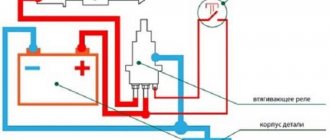
Let us dwell in more detail on protection against polarity reversal and short circuit. The scheme is a kind of “KNOW-HOW” in its simplicity and reliability. The advantage is that you do not need to use a powerful relay or thyristor, which has a voltage drop of about two volts. The circuit as an independent device can be built into any charger and power supply. Exit from the protection mode is automatic as soon as the short circuit or overpolarity is eliminated. When triggered, the “connection error” LED lights up.
Description of operation: In normal mode, the voltage through the LED and resistor R9 unlocks VT1 and all voltage from the input goes to the output. During a short circuit or polarity reversal, the current pulses sharply increases, the voltage drop across the field switch and the shunt increases sharply, which leads to the opening of VT2, which in turn bypasses the gate source. The additional negative voltage relative to the source (drop across the shunt) covers VT1. Next, an avalanche process of closing VT1 occurs. The LED is illuminated through open VT2. The circuit can remain in this state for as long as desired until the short circuit is eliminated. To additionally charge motorcycle batteries, you can add a switch that connects an additional selected resistor in pin 1 circuit of the TL494. The design will be universal if you install a variable resistor. The output voltage can be adjusted up to 20 volts.
If you put a bridge in the 12V output channel, then you can regulate the voltage up to 35 volts. Further improvements are limited only by imagination. In order not to be unfounded, I provide photos of the charger working. Photos of the charger working. Charging current 10 amperes.
Other circuit solutions have also been developed. To be continued…
Files:
Printed circuit boards in SL 5.0 format.
As usual, we put the questions here.
| What do you think of this article? | Did this device work for you? | |
| 150 | 1 | 3 |
| 9 | 3 |
Assembly technology
Most electronic components are best assembled on a printed circuit board. At home, the board can be made using the LUT method or the photo method. You can develop a drawing in free programs, such as LayOut or the shareware Eagle. Or you can draw in the old-fashioned way on paper and apply the design with varnish to the surface of the foil. The board is etched in a solution of ferric chloride or in the following composition:
- 100 ml pharmacy hydrogen peroxide.
- 30 g citric acid.
- Two teaspoons of table salt.
Power elements are mounted on radiators of sufficient area. They must be installed on heat-conducting paste. If the heat-removing surface of the element is not connected to the common terminal, the part is attached to the heat sink through an insulating gasket - mica or made of elastic material. The radiator can be the metal wall of the housing. You can also make the heat sink part of the design. You can organize radiator airflow - then their area can be significantly reduced. To do this, you will need a 12-volt fan, which can be connected to the output of the diode bridge.
The body can be selected ready-made or made independently. Mounted on the front panel:
- measuring instruments;
- voltage and current regulators;
- On indicators.
It is better not to use terminals and connectors to connect the wires going to the battery. The currents flow through them are large, so a potential source of additional transition resistance is undesirable. It is better to solder the wires to the board and route them through the holes in the front panel. The cross-section of the conductors should be sufficient - at least 2 sq. mm, and preferably 4 sq. mm. On the other side of the wires you need to solder alligator clips.
Charger in a homemade case.
This is not a complete overview of charging circuits for a car battery - there are a great many of them. Based on the presented designs, you can understand the principles of construction of the memory, the requirements for them, and understand the simple circuitry. Having worked out the assembly of these chargers in practice, you can later move on to more serious circuits, including the use of microcontrollers.
Related article: Homemade charger for lithium-ion batteries
Conditions for homemade battery charging
To charge the device, the following requirements must be met:
- Constant voltage setting – 14.4V;
- Possibility of charging for a long time;
- Automatic shutdown when maximum current values are exceeded;
- Protection against pole connection error. When connecting minus to plus, the charging process must be stopped.
Any violation of the above requirements may irreversibly damage your device.
Where is 12 volts and where is 5? Understanding color coding
How can you find out which wires produce which voltages? Where, for example, is 12 volts on the computer power supply? You don't need a tester for this, since all the wires coming out of the computer power supply have a strictly defined, generally accepted color. Therefore, instead of a tester, we arm ourselves with the sign below.
Colors and assignment of ATX power supply wires
| Color | Purpose | Note |
| black | GND | wire common minus |
| red | +5 V | main power bus |
| yellow | +12 V | main power bus |
| blue | -12 V | main power bus (may be missing) |
| orange | +3.3 V | main power bus |
| white | -5 V | main power bus |
| violet | +5 VSB | standby food |
| grey | Power good | nutrition is normal |
| green | Power on | command to start power supply |
The plate does not require any special explanation. We got acquainted with the green wire (Power on) in the previous section - the motherboard sends a low-level signal to it (short to common) to turn on the power supply. The blue wire may be missing in new power supply models, since motherboard manufacturers have abandoned the RS-232C interface (COM port), which requires -12 V.
The purple wire (+5 VSB) is just the standby +5 V that powers the standby nodes of the motherboard. Via the gray wire (Power good), the power supply reports that all voltages are normal and the computer can be turned on. If any of the voltages during operation goes beyond the permissible limits or disappears, the signal is removed. Moreover, this happens before the storage capacitors of the power supply have time to discharge, giving the processor time to take emergency measures to stop the system in an emergency. The remaining wires are power wires for the motherboard and peripheral devices - disk drives, external video cards, etc.
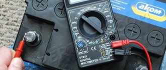
The nuances of battery operation
The most common type is the lead-acid battery. The service life of the device is calculated on average for 5 years. Recharging such batteries requires using at least 10% of the current from the total capacity of the device.
For example, with an indicator of 75Ahh, a minimum current value of 7.5A is required for charging. If the current is higher, the battery will not fail, but the car may lose its brains.
Repairing the control unit for air conditioning, gearbox, alarm system, and so on is not a cheap pleasure.
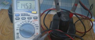
A device with a voltage of 11.9-12.1 Volts is discharged; in working condition, the charge level should be 12.5-12.7 Volts.
How to turn on the power supply from a computer without a computer
So, we have in our hands an ATX computer power supply. First of all, let's try to turn it on. But to do this you need to know some of the intricacies of how this device works. Suppose we have a computer in front of us. We plug it into the network, but outwardly nothing happens. This would seem to be clear - the machine is turned off, and to turn it on, you need to press the power button on the front panel of the system unit.
Actually this is not true. As soon as we inserted the plug into the socket, a small part of the circuit in the power supply started working, producing a standby voltage of +5 V. This part is called the standby power module. Voltage is supplied to the motherboard and powers its individual components, one of which is designed to turn on the computer.
Important. Most ATX power supplies have an additional service mechanical switch located on the back of the PC. The mains voltage is supplied to the power supply of these models after turning on this toggle switch.
A mechanical switch is used to supply voltage to this power supply.
By pressing the button on the front panel of the system unit, we thereby send a command to the motherboard (more precisely, its switching unit) to start the power supply. The node sends a Power on signal to the power supply unit, and the power supply unit, and therefore the computer itself, turns on.
Since we don’t have a computer, we will have to send this signal ourselves. This is not difficult to do. To do this, just find the connector on the power supply that powers the motherboard and install a jumper between the green and any of the black wires. So, we install a jumper, connect the power supply to the network, and it starts up immediately - you can hear it even from the noise of the fan.
Charger Features
- limit voltage 14.2 V
- minimum output voltage (battery discharged) 6 V
- charging current switchable 0.8 A / 3.5 A
Additionally, you will need LED indicators: green and red, NPN transistor. The red LED indicates that the battery is charging, and the green LED indicates that the maximum voltage has been reached (charging is complete).
We warn you: the network adapter contains voltages that are dangerous to life and health. Such modifications should only be undertaken by experienced electronics engineers who have experience working with switching power supplies!
The modification only affects elements on the secondary side of the transformer. The idea is based on correcting (if necessary) the output voltage of the power supply, adding a current limiter and LEDs that inform about the operating mode of the charger.
Microwave oven charger
Some car enthusiasts use a transformer from a broken microwave oven. But this transformer will need to be redone, since it is a step-up transformer, not a step-down transformer.
It is not necessary that the transformer be in good working order, since the secondary winding in it often burns out, which will still have to be removed during the creation of the device.
Remaking the transformer comes down to completely removing the secondary winding and winding a new one.
An insulated wire with a cross-section of at least 2.0 mm is used as a new winding. sq.
When winding, you need to decide on the number of turns. You can do this experimentally - wind 10 turns of a new wire around the core, then connect a voltmeter to its ends and power the transformer.
According to the voltmeter readings, it is determined what output voltage these 10 turns provide.
For example, measurements showed that there is 2.0 V at the output. This means that 12V at the output will provide 60 turns, and 13V will provide 65 turns. As you understand, 5 turns adds 1 volt.
Scheme.
Well, then everything is done as described above - the diode bridge is made, all the components are connected and the functionality is checked.
It is worth pointing out that it is better to assemble such a charger with high quality, then place all the components in a case that can be made from scrap materials. Or mount it on a base.
Be sure to mark where the “positive” wire is and where the “negative” wire is, so as not to “over-plus” and damage the device.
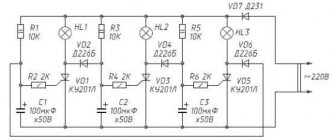
Using a lamp and a semiconductor diode
This method of recharging a battery device is relevant at home. To implement this, you must have a 220V outlet.
- The circuit elements include a standard 100-150 Watt incandescent lamp, a semiconductor diode, a socket plug and a cable with crocodile clips.
- In this connection, the diode serves as a voltage converter from AC to DC.
- To prevent a short circuit, it is enough to use a 10-15 A fuse. The lamp and diode must be connected to the “+” of the battery.
With a lamp power of 100 watts, the incoming current will be 0.17A. To achieve a value of 2A, you will need to charge the battery for at least 10 hours.
Most likely, it will not be possible to completely restore the charge of a dead battery, but it will be enough to start the car.
Operating rules
The disadvantage of a homemade charger for a 12V battery is that after the battery is fully charged, the device does not automatically turn off. That is why you will have to periodically glance at the scoreboard in order to turn it off in time. Another important nuance is that checking the charger for spark is strictly prohibited.
Every car owner needs a battery charger, but it costs a lot, and regular preventive trips to a car service center are not an option. Battery service at a service station takes time and money. In addition, with a discharged battery, you still need to drive to the service station. Anyone who knows how to use a soldering iron can assemble a working charger for a car battery with their own hands.