09/15/2020 Author: VT-METALL
Issues discussed in the material:
- Types of water pipelines and proper welding of pipes
- How to choose electrodes for proper pipe welding
- Methods and tips for proper pipe welding
- Preliminary work for proper pipe welding
- Correct pipe welding: step-by-step algorithm
- Safety precautions when welding pipes
Proper welding of pipes is a real art that allows you to create durable plumbing. Often, households use inexpensive and lightweight plastic pipes or easy-to-install profiles. However, these options are not always practical.
In order for the water supply to serve for a long time, it is important to correctly organize the entire work process: from the choice of electrode to the welding technology.
Types of water pipelines and proper welding of pipes
A variety of pipelines are used to move different materials and fluids. Depending on their purpose, they can be:
- technological;
- main lines;
- industrial;
- gas supply pipelines;
- water;
- sewer.
Pipelines are made of ceramics, plastics, concrete and metals.
Proper welding of pipes is carried out in one of the following ways:
- Mechanical, in which the result is achieved through friction.
- Thermal, during which materials melt (gas, plasma, electric arc welding).
- Thermomechanical, which is performed by butt contact method using a magnetically controlled arc.
Types of welding can be classified on various bases. Before you start processing pipes, you should choose the most suitable method. Theoretically, any of them is suitable for working with pipes of different diameters. Pipelines can be welded using pressure (gas press, cold, ultrasonic and contact welding) or melting (electric arc and gas). Most often, manual or mechanized electric arc methods are used to properly weld pipe joints.
Requirements for preparing pipelines for welding
Preparing parts for welding
6.1. All blocks, pipes and parts arriving at the installation site must be checked by a foreman or other responsible person for marks and markings before assembly begins.
6.2. In rain, wind and snow, all work should be carried out with proper protection of work areas.
6.3. The assembly of pipe joints, as well as pipes to the fittings of manifolds and drums, should be carried out in a sequence that provides free access to the joints for welding and quality control of seams, and, if necessary, for correcting defects.
6.4. It is prohibited to subject the assembled components of pipelines and pipes of the heating surfaces of boilers to any load in order to avoid the formation of cracks in the seams.
6.5. When preparing butt joints of pipes for welding, it is necessary to check their compliance with the drawings and the requirements of regulatory and technical documentation. Pay attention to the perpendicularity of the cutting plane to the pipe axis (Fig. 2). The deviation of the cutting plane from the square “L” should not exceed the values indicated in the table. 4.
You should also check:
compliance of the shape, size and quality of edge preparation (including boring for a backing ring or for a given internal diameter, as well as cutting for corner and T-joints) with the requirements (processing of chamfers for welding and the dimensions of the edges should be checked with special templates);
quality of cleaning of the outer and inner surfaces of pipe ends (nozzles, fittings), as well as their surfaces in places of corner and T-joints;
correct execution of transitions from one section to another (at the ends of pipes, pipes and fittings subject to welding with elements of other standard sizes);
compliance with the minimum actual wall thickness of pipe ends prepared for welding (nozzles, parts, fittings) established by the tolerance (after boring for a backing ring or for a given internal diameter or cleaning the outer and inner surfaces after calibration).
Table 4
| Pipe outer diameter, mm | Up to 63 (inclusive) | 76-125 | 125-219 | 273-529 | More than 529 |
| Permissible plane skew L, mm | 0,5 | 1,5 | 2,5 |
Rice. 2. Checking the perpendicularity of the pipe ends
6.6. When processing pipe ends, the length of the cylindrical bore L for the backing ring (Fig. 3) must be at least 20 mm for pipe wall thicknesses up to 25 mm inclusive, and at least 50 mm for greater thicknesses. The transition from the machined section to the untreated surface of the pipe should be smooth with a cutter exit angle of no more than 15 º. Boring may not be carried out if the internal diameters of the pipes being joined differ by no more than 2 mm.
6.7. Processing of the ends (cutting pipes and chamfering) must be done mechanically using special pipe cutting machines. The surface roughness of the pipe edges must correspond to the data shown in Fig. 3. It is allowed to process the ends of pipes with gas cutting, but with subsequent cleaning of the edges with a cutting or abrasive tool until traces of fire cutting are removed.
6.8. Oxygen cutting of pipes made of chrome-molybdenum and chrome-molybdenum-vanadium steels with a wall thickness of more than 12 mm at an ambient temperature below 0 ºС must be carried out with preliminary heating up to 200 ºС and slow cooling under a layer of asbestos.
Rice. 3. Roughness of edge surfaces
6.9. If the difference in internal diameters of the pipes being joined exceeds the permissible limit (clause 6.18), then one of the following methods can be used to ensure a transition at the junction:
a) distribution (idle or with heating) of the end of the pipe with a smaller internal diameter by calibrating it (Fig. 4a).
The scope of application of the method and the permissible distribution value are given in table. 5. After distribution, it is necessary to check whether the pipe wall has become thinner than the permissible size;
b) mechanical processing (boring) on the inner surface of the end of the pipe with a smaller diameter in accordance with Fig. 4b (for a joint without a backing ring) or Fig. 4c (for a joint with the remaining backing ring), provided that the pipe wall thickness after boring will not be less than the calculated one. This method can be used for pipes made of any steel. The cutter exit angle should be no more than 15º.
Table 5
| Steel | Distribution method* | Pipe diameter, mm, no more | Pipe wall thickness, mm, no more | Distribution ** A, %, no more |
| Carbon | Cold | |||
| 84-200 | ||||
| Heated | ||||
| Low alloy: | ||||
| heat resistant | Cold | |||
| Heated | ||||
| structural | Cold | |||
| Heated |
* Distribution with heating should be carried out at a temperature of 900-1000 ºС for the ends of pipes made of low-alloy heat-resistant steels, at 700-900 ºС for low-alloy structural and carbon steels.
** Calculated using the formula A = (D2 – D1) 100 / D1, where D1 and D2 are the internal diameter of the pipe before and after distribution, respectively.
6.10. When joining pipes with different outer diameters, the size h (Fig. 5) should be no more than 30% of the thickness of the thinner pipe, but no more than 5 mm. If the difference in outer diameters exceeds this, the end of the pipe with the larger outer diameter must be machined (see Fig. 5).
Rice. 4. Methods for processing pipe ends when joining elements with different internal diameters
Rice. 5. Processing of pipe ends when joining elements with different outer diameters
6.11. Dents at the ends of pipes can be corrected using expanding devices, provided that the depth of the dents does not exceed 3.5% of the pipe diameter and the wall thickness is not more than 20 mm. Dents on pipes can be fixed by drying or heating.
The ends of pipes with dents with a depth of more than 3.5%, as well as with nicks with a depth of more than 5 mm, should be cut off or corrected by surfacing.
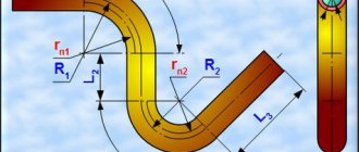
6.12. It is allowed to bend pipes under installation conditions on pipes made of low-carbon and low-alloy structural steels at an angle of no more than 15 ºС, and on pipes made of chrome-molybdenum steels - no more than 10 ºС.
Pipes made of heat-resistant steel, regardless of the wall thickness, when bending, should be heated at the bending point to a temperature of 710-740 ºС. Pipes made of low-carbon and low-alloy steels can be bent in a cold state with a wall thickness of up to 20 mm; for greater thickness - heated to 650-680 ºС. After bending, the heated area must be wrapped in asbestos to slowly cool the metal. The bending point must be located outside the bend of the pipe and, with a diameter of more than 100 mm, be at least 200 mm away from it. The heating temperature is controlled using thermal pencils, thermal paints or thermocouples, and the TTTs-1 device (Vatra). Heat treatment of the hem area is not required.
6.13. The edges of cast pipeline parts must be prepared only in the factory.
Assembling pipe joints
6.14. To secure pipe joints in a position fixed for welding, centering devices should be used and tacks should be installed.
Pipe welding centralizers models TsT-60, TsT-114, TsT-426, manufactured by Poltavsky, can be used as centering devices (recommended Appendix 7, Fig. 1-3). Pipes with a diameter of up to 50 mm can be assembled using pliers (Appendix 7, Fig. 4), and pipes with a diameter of 133-377 mm - using a clamp-type device (Appendix 7, Fig. 5). The assembly of pipes with a diameter of more than 100 mm can be done using clamping angles or compensation strips (Appendix 7, Fig. 6).
6.15. In the case of assembling a joint of pipes made of chrome-molybdenum steels using angles or compensation strips, welding of these elements to the pipes should be done using electrodes of the E46A or E50A type with preheating of the welding site. Corners and strips can be removed (mechanically or gas cutting) only after applying at least two or three first layers of seam. The places where these parts are welded to the pipes must be cleaned and carefully inspected for detection and removal of surface cracks.
It is recommended to make corners and compensation strips from carbon steel 20, St2, St3.
6.16. The structural dimensions of welded joints in accordance with GOST 16037 are given in the recommended Appendix 8.
6.17. Immediately before assembling the edges, the inner and outer surfaces of the pipes in an area of at least 20 + 20 mm from the ends must be cleaned to a metallic shine and degreased. Before installing the fitting (pipe) into the manifold or drum, the surfaces around the hole must be cleaned 15-20 mm from the side of the weld and the surface of the hole must be cleaned to the full depth.
6.18. The displacement of the internal surfaces of welded pipes (and shaped parts) when welding joints with one-sided cutting of edges without a backing ring should be no more than the values indicated in the table. 6.
For pipes with a diameter of more than 200 mm, the displacement of the inner edges should be no higher: for a tube thickness S up to 4 mm - 0.2S, for a larger thickness - 0.15S, but not more than 2 mm.
Table 6
| mm | |||
| Pipe wall thickness, S | to 10 | Over 10 to 20 | Over 20 |
| Maximum permissible displacement of internal edges | 0,5 | 0.05S |
6.19. For pipe joints assembled and welded on the remaining backing ring, the difference in the internal diameter of the elements at the joint should not exceed 2 mm so that in the assembled joint the gap between the ring and the inner surface of the element is no more than 1 mm.
6.20. The displacement from the outside of the surface of welded pipes and equipment elements with the same wall thickness should not exceed the values specified in table. 7.
Table 7
| Nominal wall thickness of connected elements (parts), S, mm | Maximum permissible displacement (mismatch) of edges in butt joints, mm | ||
| longitudinal, meridional, chordal and circular on all elements, as well as annular when welding bottoms | transverse ring | ||
| for pipe and conical elements | for cylindrical elements made of sheet or wire | ||
| 0-5 | 0.20S | 0.20S | 0.25S |
| >5-10 | 0.10S + 0.5 | 0.10S + 0.5 | 0.25S |
| >10-25 | 0.10S + 0.5 | 0.10S + 0.5 | 0.10S + 0.5 |
| >25-50 | 3 (0.04S + 2.0)* | 0.06S + 1.5 | 0.06S + 1.5 |
* May only be permitted in cases specified in the working drawings. In butt welded joints made by electric arc welding on both sides, the specified edge displacement should not be exceeded on either the outer or inner sides of the seam.
6.21. The straightness of the pipes at the joint (no fractures) and the displacement of the edges are checked with a 400 mm long ruler applied in three to four places around the circumference of the joint (Fig. 6).
The maximum permissible clearance “a” between the end of the ruler and the surface of the pipe in an assembled (but not welded) joint should not exceed 1.5 mm at a distance of 200 mm from the joint. In a welded joint it should be no more than 3 mm.
Rice. 6. Checking the correct assembly of the butt joint
6.22. The location of transverse welds on pipes (Fig. 7) must meet the following requirements:
Distance between the axes of adjacent transverse seams l1, at S, mm
| up to 8 | at least 50 |
| more than 8 | not less than 3S, but not less than 100 |
Distance from the beginning of the bend (rounding) to the axis of the transverse seam l2, from the outer surface of the element (drum, chamber, transit pipe) to the axis of the transverse seam l3 or to the beginning of the bend l4 at Dn, mm:
| up to 100 | not less than Days, but not less than 50 |
| more than 100 | not less, but not less than 100 |
Rice. 7. Location of transverse welds
6.23. When assembling pipes and other elements that have longitudinal or spiral seams, subsequent ones must be offset from one another.
The displacement (for pipes Ø > 100 mm) must be at least three times the wall thickness of the pipes (elements) being welded, but not less than 100 mm.
Welding the backing ring
6.24. When assembling pipeline joints with backing rings, there should be no distortion of the backing ring. Tacking and welding of the backing ring is carried out by a welder who will subsequently weld this joint, or by a welder who has a certificate for the right to weld such joints. The sequence of assembling the joint with the backing ring should be as follows:
the backing ring should be installed in one of the pipes with a gap between the ring and the inner surface of the pipe of no more than 1 mm;
tack the ring from the outside in two places and then weld it to the pipe using a thread seam with a leg no more than 4 mm (Fig. 8a). Tack welding and welding of a ring to a low-alloy steel pipe should be performed with preheating of the end of the pipe and the backing ring in accordance with the data in Table. 9;
clean the thread seam from slag and splashes;
slide the second pipe to be joined onto the protruding part of the backing ring (the gap between the end of the thread seam and the second pipe should be 4-5 mm), check that the joint is assembled correctly;
Weld the backing ring with a thread seam to the second pipe (Fig. 8b);
preheat the joint in accordance with the requirements of the table. 9.
The root layer should be welded with electrodes with a diameter of 2.5-3 mm.
During the assembly process, pipes with a welded ring should not move or be subject to impacts on the edges and the ring.
Rice. 8. Welding the backing ring a – to the first pipe; b – to the second pipe
6.25. Backing rings for joints of pipes made of low-carbon and low-alloy steels should be made of steel 20 or other low-carbon steel of mild or semi-mild smelting with a carbon content of no more than 0.24%; For joints of pipes made of low-alloy heat-resistant steels, backing rings made of steel 12Х1МФ can be used. Dimensions of the backing ring: width – 20-25 mm, thickness – 3-4 mm. If the ring is made of strip steel, the butt seam of the ring should be cleaned flush.
Previous3Next
Conflicts in family life. How can I change this? It is rare that a marriage and relationship exists without conflict and tension. Everyone goes through this...
What will happen to the Earth if its axis shifts by 6666 km? What will happen to the Earth? - I asked myself...
WHAT HAPPENS IN ADULT LIFE? If you are still connected to your mother in the wrong way, you are avoiding separation and independent adult existence...
What to do if there is no reciprocity? And now let's come down from heaven to earth. Have you landed? Let's continue the conversation...
Didn't find what you were looking for? Use Google search on the site:
How to choose electrodes for proper pipe welding
Before you start welding heating pipes or any other pipes, you need to stock up on electrodes. Their quality directly affects the reliability of the resulting connection, the tightness of the structure, as well as the welding process itself.
Electrodes are a thin steel rod with a special coating that provides a stable arc during operation and forms a weld that prevents oxidation of the metal.
VT-metall offers services:
Electrodes are qualified by the type of core and outer coating.
Depending on the type of core, electrodes are divided into:
- consumables with a non-melting center made of graphite, electrical coal or tungsten;
- with a melting center - wire, the thickness of which varies depending on the type of work performed.
Based on the type of external coating, electrodes are divided into the following groups:
- With cellulose coating (grade C). Designed for proper welding of large diameter pipes; they are used to install gas and water mains.
- With rutile acid coating (RA). Used to work with metal heating or drainage pipes. The resulting weld is covered with a small layer of slag, which is removed by tapping.
- Rutile coated (RR). Allows you to obtain neat welding seams with slag that can be easily removed from the surface. These electrodes are used for corner joints, as well as when welding the second or third layers of metal.
- With rutile cellulose (RC) coating. They can be used for correct welding of pipes in any planes, for example, when creating a long vertical seam.
- With base coat (B). These are universal consumables suitable for working with thick-walled pipes and parts intended for use at sub-zero temperatures. Allows you to obtain a high-quality plastic seam that is not subject to cracking or deformation.
Before starting welding work, it is worth obtaining advice from welding specialists regarding their preferred brands of electrodes. At the same time, there can be quite a lot of recommendations, and consumables may vary depending on the store or city.
We recommend articles on metalworking
- Steel grades: classification and interpretation
- Aluminum grades and areas of their application
- Defects in metal products: causes and search methods
There is a direct connection between the cost and quality of consumables. With cheap electrodes it is difficult to weld pipes correctly and obtain a high-quality weld. Therefore, there is no need to save on these consumables.
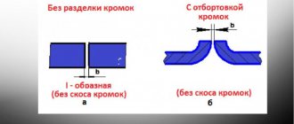
Purpose of cutting edges for welding
Cutting allows you to solve two main problems: penetration throughout the entire thickness of the sheet and high-quality penetration of the root of the seam. The bevel created during cutting ensures a smooth transition from one part to another, which reduces mechanical stress. Without a correctly executed bevel, the electrode will not be able to reach the root of the seam and achieve full penetration. A separate issue is cutting when welding pipes and vessels, as well as welding bends and fittings to pipes.
Preparation of edges for welding
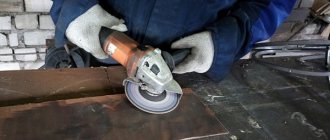
The process of preparing edges for welding can be divided into two stages: cleaning
and
cutting
. Cleaning is carried out in order to remove all foreign inclusions and minor defects in the surface of the part. Edge processing is carried out until the surface has a metallic shine. The part is cleaned on both sides with a strip of up to 20 mm. Next, the ends and blunt ends are cleaned.
For small volumes of work, cleaning is carried out with hand-held metal brushes, files and sanding paper. Places contaminated with oil and preservative compounds are scraped off with scrapers and wiped with solvents. For large volumes of work, mechanical wire brushes or sandblasters are used. Contaminants are combated by etching in solutions of alkalis and acids, followed by rinsing with clean water.
Edge cutting
Depending on the thickness of the metal being welded, cutting is carried out either on one or both sides. In any option, the bevels are made without a sharp edge, and the last millimeters are dulled, achieving a flat edge. Cutting can be done by mechanical processing using the following operations:
- chiselling;
- planing;
- milling.
Straight joints are prepared on planing machines. The forward movement of the cutter allows you to remove excess metal and obtain the desired shape. It is somewhat more difficult to process curved seams. In such cases, it is necessary to use milling machines. The movement of the cutter can be controlled manually, but special programs are more often used. Thus, processing is faster and more accurate. With a complex seam configuration, manual control of the cutter movement is impossible.
When preparing products that cannot be installed on a machine due to their large size or shape, portable edge scrapers are used. They are installed directly on the workpiece and process it. As you might guess, the shape and quality of the chamfer surface leave much to be desired, and the workpiece requires additional processing.
Abrasive processing is used as an additional treatment after milling and chipping, as well as when removing minor flaws on small parts from the surface.
When cutting edges using thermal methods, the following is used:
- gas cutting (oxygen);
- plasma cutting;
- laser cutting.
The use of gas cutting for alloy steels is limited by the formation of difficult-to-remove carbides on the edge surface. This type of cutting is used mainly for preparing products made of carbon steels. Plasma cutting works much better. The high temperature of the plasma allows you to obtain a high-quality edge on workpieces made of any materials. Laser cutting is still extremely rare; it gives excellent results, but is very expensive, so it is used only for cutting seams on the most critical products.
The following edge bevel shapes are used: V-shaped, X-shaped, U-shaped
and
K-shaped
.
V shape
This is the most popular type of cutting. The popularity is easily explained by the comparative simplicity of execution and the possibility of application on metals of various thicknesses.
X shape
Used when welding thick-walled metals.
U shape
This difficult-to-make bevel is used for welding thick-walled metals. It is most often used in manual arc welding, since this results in significant savings in electrodes.
K-shaped bevel
used extremely rarely. It resembles an X-shaped bevel made on one half of the workpiece.
Methods for proper pipe welding
There are various methods for properly welding polypropylene pipes and products made from other materials using the electric arc method:
- end-to-end - in this case the pipeline elements are located opposite each other;
- in a T-bar - in this case, the pipe sections are located perpendicular to each other (in the shape of the letter “T”);
- overlap - this method involves flaring one of the pipes, allowing it to be put on the other;
- angular method, in which the elements are placed at an angle of 45° or 90° relative to each other.
In the process of proper pipe welding, the following types of seams are obtained:
- horizontal (with a vertical arrangement of pipeline elements);
- vertical (if the pipes are located vertically);
- ceiling (with the electrode placed above the welder’s head, in the lower part of the workpiece);
- lower ones (you have to bend over to do this).
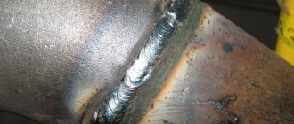
If it is necessary to connect steel pipes, the butt method is used. In addition, the joint must be welded to the thickness of the workpiece wall. A bottom turning seam is best for this.
To obtain a high-quality welded joint during the work process, you should adhere to the following recommendations:
- During welding, the electrode should be positioned at an angle of 45° or slightly less. This will reduce the amount of molten metal entering the pipeline element being welded.
- For T-welding or butt welding, 2-3 mm electrodes will be required. A high-quality welded joint will be obtained with a current varying from 80 to 110 amperes.
- To get a reliable overlap connection, you will need to increase the current to 120 amperes; 2-3 mm consumables (electrodes) are also suitable.
- The weld seam should rise 3 mm below the surface of the workpiece being welded, after which we can talk about completing the work.
Correct welding of profile pipes is carried out spot-welding, that is, first two points located on opposite sides of the profile are welded, then two other points, continuing work until the entire pipe is heated. Next, a welding seam is formed along the entire perimeter of the workpiece.
Manual arc welding methods for pipes
There are two main methods of manual electric arc welding of pipes: rotary and fixed. In practice, the possibility of their use is dictated by the technical features of the pipes, their location and the qualifications of the welder. There is also a combined method, but it has not found widespread use.
Welding with joint rotation
The rotating method ensures maximum strength and uniformity of the seam. This can be achieved using two tricks. Firstly, try to keep the electrode strictly at a right angle to the axis of the pipe, that is, regulate the intensity of melting not by tilting the electrode, but by the length of the arc. Secondly, work using three-pass technology. It involves the following sequence of actions:
- Conventionally divide the end of the pipe into four equal segments , you can make corresponding marks, but it is better to weld the pipes in these zones point by point.
- Boil the joint in the root part of the segments located opposite each other with a thin electrode (3-4 mm) with a current of 120-150 A.
- Rotate the pipe 90° and weld the remaining two segments with the same parameters.
- Gradually turning the pipe, weld it over its entire diameter . The welding parameters will also change - the electrode size will be 5-6 mm, and the current will be 200-250 A.
- Repeat the steps indicated in point 4.
If the design involves welding pipes on the same axis in several sections, perform operations simultaneously at all joints. This will not only speed up the work, but will also prevent any axial displacement during the welding process.
Welding without joint rotation
Welding without rotation is advisable when it is carried out on an already assembled structure, including those with hard-to-reach places. The technology is in many ways similar to rotary, but there are a number of significant differences in the length of individual seams. The general algorithm includes the following steps:
- A thin electrode (4 mm) is used to weld up to half the length of the joint..
- The remaining segment is conventionally divided into two equal parts , which are welded with a thin electrode in different directions.
- Half of the joint is re-welded with a thick electrode (5-6 mm), and it should not exactly repeat the location of the very first seam, but should partially overlap it (about 30°).
- The remaining segment is conventionally divided into two equal parts and welded with a thick electrode in different directions.
The third pass is usually used only when welding pipes with a diameter greater than 700 mm. It involves applying two seams of equal length in opposite directions, the joints of which do not coincide with the joints of the seams applied previously.
Preliminary work for proper pipe welding
Before you begin to properly weld plastic and metal round pipes, you need to pre-process the joints and clarify a number of nuances. First of all, they diagnose the pipe’s compliance with certain technical characteristics that apply to the installed system, in particular to the water supply system.
Necessary:
- observe geometric dimensions;
- have a quality certificate, especially if a pipeline for drinking water supply is to be installed;
- so that the pipe is perfectly round in shape, since defects, a flattened or oval section of the workpiece are not acceptable;
- control the wall thickness along the entire length of the pipe - it should be the same;
- The chemical composition of the part must comply with the requirements of GOST - this information is contained in the technical documentation or is determined in the process of laboratory research.
After this, you can begin preparing the pipes for joining and welding.
During the preparation process, you must complete the following steps:
- check the evenness of the cut at the end of the pipe, it should be 90°;
- thoroughly clean the end of the workpiece to be welded and the 10 mm area around it until a metallic sheen appears;
- remove residual oils, rust, paintwork from the surface of the pipe, degrease the ends of the element.
In addition, you should ensure that the end has the correct configuration. The opening angle of the edge should be 65°, the dullness index should be 2 mm. The required parameters can be obtained through additional processing.
Edge processing scheme
Before assembling the pipes you must:
- clean the internal cavity of pipes and parts from pound, mud, snow and other contaminants;
- clean the edges and adjacent internal and external surfaces of pipes, gas pipeline parts, pipes, fittings to a width of at least 10 mm to a metallic shine;
- check the geometric dimensions of the edges, straighten smooth dents at the ends of pipes with a depth of up to 3.5% of the outer diameter of the pipe;
- Clean the edges and adjacent inner and outer surfaces of the pipes to a width of at least 10 mm to bare metal.
The ends of pipes that have cracks, tears, nicks, or chamfers with a depth of more than 5 mm are cut off.
At air temperatures below minus 5 °C, straightening the ends of the fubs without heating them is not recommended.
Pipe joints are assembled on inventory benches using external or internal centralizers.
The permissible displacement of the edges of the pipes being welded should not exceed 0.155 + 0.5 mm, where 5 is the smallest wall thickness of the pipes being welded.
Welding joints of different-thickness pipes or pipes with connecting parts is allowed without special processing of the edges with a wall thickness of less than 12.5 mm (if the difference in thickness does not exceed
2.0 mm). Welding of pipes or pipes with connecting parts and fittings with greater variations in thickness is carried out using a standard transition of at least 250 mm in length.
In the absence of standard transitions, it is allowed to make overlap joints “pipe in pipe” with dimensions */50x40, 40x32, 32x25, 25x20 mm on overhead and internal low-pressure gas pipelines.
Welding of lap joints is carried out in accordance with GOST 16037 with the following requirements:
- the gap between pipes connected with an overlap is no more than 1-2 mm and is equal around the perimeter;
- the amount of overlap along the length of the connected pipes is at least 3 cm;
- at the end of a pipe of smaller diameter, a chamfer is made inward at an angle of at least 45° throughout the entire thickness of the pipe wall;
- connection of welded ends after special preparation (thinning) of the edges from the inside or outside of a thicker-walled element with wall thickness S3 to thickness S2 of the welded end, which does not exceed 1.5 times the thickness of the less thick-walled element S1.
Correct pipe welding: step-by-step algorithm
In electric welding, a strong connection between workpieces is achieved through a thermal process. In this case, the quality of the seam will be higher than with gas welding.
If the pipes are located in an accessible place and can be rotated, then it is necessary to connect the two pipeline elements end-to-end with one or three electric welding points, and then continue welding the workpieces:
- continuously (if it is possible to rotate the parts);
- with a separation, starting from the bottom, if the pipe is located inconveniently and there is no way to rotate it.
Welding work is performed in two approaches. Initially, the first seam (“root”) is made, covering 2-3 mm of the joint of the workpieces, after which the resulting deposits and scale are removed. Then a second seam is formed, which is also cleaned.
The algorithm for proper pipe welding is as follows:
- Before you start working directly, you need to take a stable position and take care of good lighting of the space.
- Light the arc, increasing the current if necessary.
- Place the electrode at the beginning of the weld, form a weld pool, maintaining a constant arc gap.
- A sufficiently large current will cause particles of straightened metal to follow the heat.
Movements must be adjusted and careful, since too much current will cause the metal to melt too much, begin to bubble, and it will not be possible to form a weld. - In the process of properly welding pipes, it is necessary to ensure that the edges are filled and that there are no undercuts.
If the current is low, then the weld pool will be equal to the outline of the electrode. By increasing the current, moving the electrode in a circle or from side to side, you can form the correct welding seam. Attention should be paid to the quality of welding during the processing of workpieces, ensuring the uniform filling of the weld pool. - Place a point, leaving a small amount of metal.
- Extinguish the arc along the seam.
Over time, you can learn how to properly weld pipes and form high-quality seams, but it will be easier for those who previously observed the work from the outside or were a welder’s assistant.
Safety precautions when welding pipes
During electrical work, including pipe welding, it is necessary to comply with safety requirements. Their violation can result in various injuries, for example, thermal burn of the skin or retina due to an arc flash, electric shock, etc.
To avoid trouble, you should pay attention to the following before starting work:
- electrical wires and parts of the welding machine must be insulated;
- the body of the welding equipment and additional devices must be grounded;
- You can only wear completely dry overalls and gloves;
- for additional insulation it is necessary to use galoshes or a rubber mat (for a small room);
- Be sure to protect your eyes and face by wearing a protective shield.
By following the information presented in the article, you can independently learn how to properly weld pipes using electrical equipment. However, it is impossible to achieve success without practical skills. Using our recommendations, you can start practicing welding and over time get decent results in welding metal pipelines.
Preparing pipes for welding
Cleaning pipe joints
It is recommended to clean welded pipes as follows. Traces of oils, paints, varnishes and other organic coatings are removed using gasoline or a special solvent. Dirt and rust from the edges can be cleaned with steel brushes or abrasive wheels.
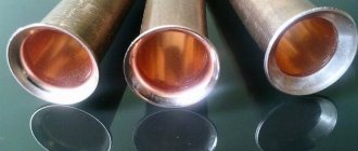
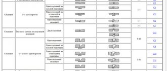
Cutting pipe edges for welding
When preparing pipe joints for welding, it is necessary to check the following indicators: the perpendicularity of the pipe end to its longitudinal axis. The total opening angle of the joint should be 60-70°. The amount of dullness is 2-2.5 mm. Chamfers from the ends of pipes can be removed by mechanical processing, gas cutting or other methods that allow you to obtain the desired shape, size and surface quality of the processed edges. The edge cutting diagram is shown in the figure on the right:
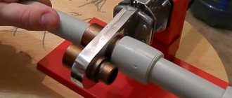
Assembly of pipes for welding
When assembling pipe joints, it is necessary to align their edges so that the joint surfaces of both pipes coincide and the axis of the pipeline is not displaced. The gap between the edges should be within 2-3mm and it should be uniform over the entire diameter.
Assembly and centering can be done manually, but the disadvantages of this process are that it is quite labor-intensive and cannot provide high accuracy. Centralizers are used to assemble pipes in production. To align the joints of large-diameter main pipes, internal centralizers are used, which allow the pipes to be centered along the inner diameter.
External centralizers allow you to center pipes along the outer diameter and their design is simpler than that of internal centralizers. But with a large difference in pipe wall thickness or with high pipe flexibility, it is more difficult to ensure good welding quality using an external centralizer.
After assembling pipes with a diameter of up to 300 mm, the joints are fastened with tacks, 50-80 mm long in 4 places. When welding pipes with a diameter of more than 300mm, the tacks are placed evenly around the circumference, and the recommended distance between the tacks is 250-400mm.
Tacks are an integral part of the weld and they must be performed by the same welders who will subsequently weld the pipeline joint using the same electrodes.
When assembling with internal centralizers, instead of tack welding, it is better to perform continuous welding of the root of the seam. Especially if the ambient temperature is low. This technique allows you to reduce internal stresses and reduce the risk of hardening cracks in the weld metal and heat-affected zone.