CNC press brakes are designed for cold deformation of thin sheet metal. Due to automation, high bending accuracy is ensured, productivity increases compared to conventional machines, and the creation of structures with different geometries is simplified. Designed for serial production of parts.
CNC Press Brake
What is a CNC Press Brake
CNC sheet bending is high-performance pneumatic equipment designed for processing workpieces made of various metals. Allows you to bend thin sheets evenly and give them the desired shape. The presence of a CNC ensures process automation, more accurately controls mechanisms, and monitors the current state and sensor readings.
Unlike conventional mechanical analogues, such machines minimize the likelihood of creating defective parts. Punches and dies are easily replaced without the use of physical force.
Advantages of hydraulic sheet benders
The use of innovative developments has allowed modern devices with hydraulics to be equipped with devices and mechanisms that provide maximum quality when bending metal, making the work comfortable, and the use of machines economical. The prices of the press brakes presented in our catalog are fully justified by the efficiency of the machines, capable of bending metal sheets at a speed of 6.5 to 10 mm/sec in the manufacture of various types of profiles and bent structures of conical, rectangular and cylindrical shapes.
In comparison with other types of sheet bending machines, the hydraulic machine is distinguished by:
- a combination of compact dimensions with high power, which can range from 15 to 110 kW;
- automatic workpiece positioning and electronic measuring system;
- high performance with low energy consumption;
- safe and reliable use.
Units of various modifications produce a force when pressing metal, which can reach from 160 to 2000 tons. The use of CNC sheet bending machines offered by our company in production makes it possible to significantly increase work efficiency and the accuracy of parts manufacturing. The machines allow you to program all stages of the technological process and create elements with complex geometric shapes.
Design and operating principle
The mechanical part of the press consists of the following components:
- the bed, which ensures the stability of the machine and keeps it from swinging;
- tools for bending workpieces;
- servomotors that drive equipment;
- hydraulic drives;
- guides for moving the working tool.
The design also provides protection for the operator from injury:
- electronic sensors that determine machine operating parameters in real time;
- steel shield to prevent contact of the workpiece with the operator during press operation;
- electronic regulation of the position of the part on the work table;
- indicator that allows you to control the bending process.
Changes are made to the computer program of CNC machines based on the dimensions of the working tool, and readjustment is performed. It is enough to perform the setup once, and in the future you only need to download the necessary programs. The number of recorded programs depends on the memory capacity.
Beds in equipment are of the following types:
- C-shaped. Used to accommodate various equipment and press maintenance. It has a wide working area, behind which there is a pocket. The structure cannot withstand overloads (deforms).
- O-shaped. It is characterized by high strength and resistance to overloads. Finished parts are difficult to obtain. It is not possible to install auxiliary equipment on it.
The bending force depends on the strength and thickness of the metal. For aluminum, the optimal force is considered to be from 30 to 60 MPa, for low-carbon steels - from 75 to 110 MPa, for brass - from 70 to 100 MPa. Typically, up to 30% is added to the calculated press load values to increase efficiency.
The operating principle is as follows:
- A traverse is attached to the upper part of the press.
- When the program is executed, the traverse moves along vertical axes at a given speed to bend a specific metal of a certain thickness.
- When approaching the workpiece, the speed of movement of the traverse increases to working speed using hydraulics. The CNC controls the sensor parameters and is responsible for the entire bending process.
- Upon reaching the bottom point, the traverse stops and remains in this position for some time. The duration of compression allows you to give the final shape to the workpiece.
- The decompression stage begins: the traverse moves upward after pressing. The speed is determined by the technological process.
- After decompression, the speed of movement of the press increases until the top point is reached.
- To remove the workpiece, the equipment is turned off. On automated lines, the part is removed automatically, and then a new workpiece is loaded.
CNC sheet bending machine
Principle of operation
The principle by which a press brake equipped with a hydraulic drive operates is quite simple, but nevertheless ensures both high productivity of technological operations and their safety.
The matrix is placed on the lower beam of the press
The process of bending sheet metal blanks when using a machine of this category is performed in the following sequence:
- The press crossbar is fixed at the “dead center” of the sheet bending equipment, located in its upper part.
- In order for the traverse to begin to move from top to bottom at the required speed, a foot pedal or button is used to control this mechanism. Up to a certain position, the traverse moves at a free fall speed, which is higher than the speed required for bending. Despite this definition, there is no free fall of the traverse as such; each of its movements is monitored and controlled by means of appropriate equipment.
- When the traverse is as close as possible to the surface of the workpiece being processed, the working speed is imparted to the beam. All movements of the traverse, as well as the operating modes of such movements, are controlled by the hydraulic system of the press brake, and hardware control devices or special sensors are responsible for controlling such processes.
- The traverse of the machine, after imparting operating speed to it, tends to the bottom “dead point”, after reaching which it is maintained in this position for some time. Holding the traverse at the bottom “dead center” is necessary in order to ensure a uniform load on the surface of the workpiece that is undergoing the bending process.
- It is very important, after finishing bending the workpiece, to begin lifting the traverse at a certain speed, which has no less influence on the quality of the processing performed than the process of its implementation itself. The stage of the bending process, at which the traverse rises above the surface of the newly processed workpiece, is called decompression.
- After decompression is completed, the traverse returns to the top “dead center” at a sufficiently high speed.
- The equipment is turned off and the finished product is removed from the processing area.
The bending of a sheet of metal occurs under the influence of a punch mounted on the upper beam of the press
The technological process of bending a sheet metal workpiece, carried out on a press brake equipped with additional working mechanisms, may differ slightly from the scheme described above, but in general its essence remains unchanged.
When processing workpieces on a hydraulic sheet bending machine, we are guided by several basic parameters of both the equipment used and the technological process. Such parameters, in particular, include:
- working length of the equipment used;
- the force that the working body of the press exerts on the workpiece being processed;
- the productivity with which processing is performed.
In addition to the main ones, there are also a number of additional parameters that also need to be taken into account both when choosing a press and when performing processing. These parameters include:
- distance between the side posts of the machine;
- the speed at which work operations are performed;
- the maximum distance the traverse can be raised, etc.
Specifications
CNC sheet bending machines have the following parameters:
- working surface length - from 1 to 6 m;
- press force - 400–4000 kN;
- the maximum thickness of the workpiece with a material strength of 70 kgf/mm2 is up to 10 mm;
- vertical idle speed up to 120 mm/s, working speed - up to 12.9 mm/s, reverse speed - up to 130 mm/s;
- distance between racks - from 1 to 5.1 m;
- power of installed engines - up to 18.5 kW;
- table height - from 0.8 to 1.1 m;
- the total weight of the machine is from 2.6 to 300 tons.
I. Which bending method should I choose?
There are 2 main bending methods.
We speak of "air bending" or "free bending" if there is an air gap between the sheet and the walls of the V-die. This is currently the most common method.
If the sheet is pressed completely against the walls of the V-shaped die, we call this method "sizing". Despite the fact that this method is quite old, it is used and even should be used in certain cases, which we will consider below.
Free bending
Provides flexibility, but has some limitations in accuracy.
Main features
The traverse, using a punch, presses the sheet to the selected depth along the Y axis into the groove of the matrix. The sheet remains “in the air” and does not come into contact with the walls of the matrix. This means that the bending angle is determined by the position of the Y axis and not by the geometry of the bending tool.
The Y-axis adjustment accuracy on modern presses is 0.01 mm. What bending angle corresponds to a certain Y-axis position? It's hard to say because you have to find the correct Y-axis position for each angle. The difference in the position of the Y axis can be caused by the adjustment of the lowering stroke of the traverse, the condition of the bending tool and the properties of the material: thickness, tensile strength, strain hardening.
The table below shows the deviation of the bending angle from 90° at various Y-axis deviations.
Advantages of free bending
- High flexibility: without changing bending tools, any bending angle between the V-die opening angle and 180° can be achieved. For example, 86° or 28°.
- Lower tool costs.
- Less bending force compared to calibration.
- You can “play” with force: a larger opening of the matrix means less bending force. If you double the width of the groove, you only need half the force. This means you can bend thicker material at a larger opening with the same amount of force.
- Less investment as a press with less force is needed.
But this is just a theory. In practice, you can save money by purchasing a lower-pressure press that takes full advantage of air bending and spend it on additional equipment. For example, on additional backgauge axes or manipulators.
Disadvantages of Air Bending
- Less precise bending angles for thin material.
- Differences in material quality affect repeatability.
- Not applicable for specific bending operations.
Our advice
- It is advisable to use air bending for sheets with a thickness of over 1.25 mm; for sheet thickness 1 mm or less, it is better to use calibration.
- The smallest internal bending radius must be greater than the sheet thickness. If the inner radius must be equal to the sheet thickness, it is better to use the sizing method. An internal radius less than the sheet thickness is permissible only on soft, easily deformable material, such as copper.
- A large radius can be achieved by air bending by using stepwise movement of the backgauge. If a large radius must be of high quality, it is recommended to use only the special tool calibration method.
What is the bending force?
Due to the different material properties and the effects of plastic deformation in the bending zone, the required force can only be determined approximately.
We offer you 3 practical ways:
(1) table
In each catalog and on each press you will find a table with the required force (P) in kN per 1000 mm bending length (L) depending on:
- sheet thickness (S) in mm
- tensile strength (Rm) in N/mm2
- V - matrix opening width (V) in mm
- internal radius of bent sheet (Ri) in mm
- minimum height of folded shelf (B) in mm
(2) formula
1.42 is an empirical coefficient that takes into account the friction between the edges of the matrix and the material being processed.
Another formula gives similar results:
(3) "Rule 8"
When bending low-carbon steel, the opening width of the matrix should be 8 times greater than the thickness of the sheet (V=8*S). Then P = 8 x S , where P is expressed in tons. For example, for a thickness of 2mm, die opening V = 2 x 8 = 16mm means you need 16t/m.
Bending force and length
The length of the bend is proportional to the force, i.e. the force reaches 100% only with a bend length of 100%. For example:
| An effort | Bending length |
| 100% | 3.000 mm |
| 75% | 2.250 mm |
| 50% | 1.500 mm |
| 25% | 750 mm |
Our advice
If the material is rusty or not lubricated, 10-15% should be added to the bending force.
Sheet thickness (S)
DIN allows significant deviation from the nominal sheet thickness. So, for a sheet thickness of 5 mm, the norm ranges between 4.7 and 6.5 mm. Therefore, you only need to calculate the force for the actual thickness you measured or for the maximum specification value.
Tensile Strength (Rm)
Here too, tolerances are significant and can have a major impact when calculating the required bending force. For example:
St 37-2: 340 - 510 N/mm2 St 52-3: 510 - 680 N/mm2
Our advice
Don't skimp on bending force. The tensile strength is proportional to the bending force and cannot be adjusted when you need it.
Actual thickness and tensile strength are important factors when selecting the right machine with the right force rating.
V – matrix disclosure
As a rule of thumb, the opening of the V-shaped matrix should be eight times the thickness of the sheet S:
V = 8 x S
But this is only provided that S is less than or equal to 6 mm. For thicker sheets you must use:
V = 10 x S or V = 12 x S
The opening of the V-shaped matrix is inversely proportional to the required force:
- A larger opening means less bending force but a larger inner radius;
- Smaller opening means more force but smaller inner radius.
Inner bending radius (Ri)
When using the air bending method, most of the material is subject to elastic deformation.
After bending, the material returns to its original state without residual deformation (“reverse springback”).
In a narrow region around the point of application of the force, the material undergoes plastic deformation and remains in this state forever after bending.
The greater the plastic deformation, the stronger the material becomes. We call this “strain hardening.”
The so-called “natural internal bending radius” depends on the sheet thickness and die opening. It is always greater than the sheet thickness and does not depend on the punch radius.
To determine the natural inner radius, we can use the following formula:
In the case of V = 8 x S, we can say that Ri = S x 1.25
The soft and easily deformable metal allows for a smaller internal radius.
If the radius is too small, the material may wrinkle on the inside and crack on the outside of the bend.
Our advice
If you need a small inside radius, bend at slow speed and against the grain.
Minimum shelf (B)
To avoid the flange falling into the die groove, the following minimum flange width must be observed:
| Bend angle | IN |
| 165° | 0.58 V |
| 135° | 0.60 V |
| 120° | 0.62V |
| 90° | 0.65 V |
| 45° | 1.00 V |
| 30° | 1.30 V |
Elastic deformation
Part of the elastically deformed material will “spring back” after the bending force is removed. How many degrees? This is a relevant question, because only the actually obtained bending angle is important, and not the theoretically calculated one. Most materials exhibit fairly constant elastic deformation. This means that a material of the same thickness and with the same tensile strength will spring back by the same amount at the same bending angle.
Elastic deformation depends on:
- bending angle: the smaller the bending angle, the greater the elastic deformation;
- material thickness: the thicker the material, the less elastic deformation;
- tensile strength: the higher the tensile strength, the greater the elastic deformation;
- direction of fibers: elastic deformation is different when bending along or across the fibers.
Let us demonstrate the above for the tensile strength measured under the condition V = 8 x S:
| Tensile strength in N/mm2 | Elastic deformation in ° |
| 200 | 0,5 – 1,5 |
| 250 | 1 – 2 |
| 450 | 1,5 – 2,5 |
| 600 | 3 – 4 |
| 800 | 5 – 6 |
All bending tool manufacturers take elastic deformation into account when offering free bending tools. For example, the opening angle is 85° or 86° for free bends from 90° to 180°.
Calibration
Accurate but inflexible way
With this method, the bending angle is determined by the bending force and the bending tool: the material is completely clamped between the punch and the walls of the V-shaped die. Elastic deformation is zero and various material properties have virtually no effect on the bending angle.
It is difficult to calculate the required bending force. The most reliable way is to find out the required force by test bending a short sample on a hydraulic test press.
Roughly speaking, the sizing force is 3-10 times higher than the free bending force.
Benefits of Calibration
- accuracy of bending angles, despite the difference in thickness and properties of the material;
- small inner radius;
- large outer radius;
- Z-shaped profiles;
- deep U-shaped channels;
- the ability to produce all special shapes for thicknesses up to 2 mm using steel punches and polyurethane dies;
- Excellent results on press brakes that do not have sufficient precision for free bending.
Calibration Disadvantages
- the required bending force is 3 – 10 times greater than with free bending;
- no flexibility: special tool for each shape;
- frequent tool changes (except for large series).
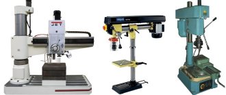
Varieties
According to the types of press mechanisms for bending sheets, there are the following types:
- hydraulic sheet bending machine - hydraulic drives are used to create force on the press;
- pneumatic - compressors are used to pump air under pressure into special pneumatic cylinders;
- electromagnetic - works on the principle of creating an electromagnetic field between the working surface and the press;
- manual - the operator uses his own strength to bend sheets;
- electromechanical - energy is transferred to the press through the operation of an electric motor and belt or chain drives.
By installation method;
- stationary;
- mobile.
According to the method of installing the workpiece inside the press:
- automatic;
- manual.
According to the principle or method of bending metal sheets:
- rotary with 2–4 shafts - the workpiece is deformed during the rolling process;
- rotary-bending - the sheet is fixed on the working surface and then deformed from bottom to top by a pressure beam;
- vertical bending - works on the principle of exerting pressure on the workpiece with a vertically moved punch; dies, press dies, and cotter pins are installed on the machines.
Introduction
Bend it - put it aside, bend it - put it aside. 25 years ago this process was a daily responsibility of the press operator. The difficulties did not end there. The operator had to constantly reconfigure the machine to obtain different bending angles, organize intermediate storage of workpieces, and perform many other actions not directly related to the production of the final part. Then the cycle repeated. Place the workpiece. Bend. Reconfigure the press. Don't forget about intermediate storage. Place the workpiece. Bend. And so again and again.
Workers who handle sheet metal today will consider such a process to be a technology of the prehistoric period. Today, the part is manufactured on an operator-friendly, ergonomic CNC press brake with automatic adjustment of all bending parameters. Different angles, different profiles on the same tool - no problem!
Machines with 4 controlled axes are now the standard rather than the exception. Presses with 8 or more axes are no longer uncommon, and they are most promising when used together with robots and press brakes.
And all this in order to produce a three-dimensional part from a flat metal sheet, be it steel, stainless steel, aluminum, magnesium, copper, brass or even gold. Everywhere you look there are sheet metal structures. It's a sheet metal boom! Even press brake manufacturers are surprised at how complex parts their customers produce. The interaction between machine tool manufacturers and their customers opens up new perspectives: engineers work together to think about how to efficiently produce a part on flexible machinery. Replacing welding with flexible welding can be very beneficial in ensuring the strength of the product. “Close to final shape” is what you can say about a part coming off a press brake that bears a close resemblance to the final product.
“Sheet” and “bending” are not associated with high technology. But in order to bend a “naughty” sheet, you need special knowledge and extensive experience. Explain to a technician who is not familiar with sheet metal that in our highly technical world, it is impossible to consistently achieve a 90° bending angle without changing settings. Sometimes it works, sometimes it doesn’t!
Without changing the program, the angle will change. For example, if a 2 mm thick sheet is made of stainless steel or aluminum, if its length is 500 mm, 1000 mm or 2000 mm, if bending is carried out along or across the grain, if the bending line is surrounded by punched or laser-cut holes, if the sheet has different elastic deformation if the surface hardening caused by plastic deformation is stronger or weaker. If, if, if...
“Bending” sounds simple, but in fact there are many nuances in this process. Therefore, I have prepared a guide that will help identify difficulties and find ways to solve them. Not through complex formulas, but through a review focused on practical application. There will be no mention of press brake manufacturers here intentionally. Leaf doesn't care about price arguments, even if the catalog is full of bright colors and promising prospects.
However, in recent years, press manufacturers have put a lot of effort into making the forming process more flexible and productive. Credit should be given to those who deserve it, because we are talking about truly high technology. But let's be realistic: traditional old press brakes with a mechanical stop in the cylinders and a synchronizing shaft are still in demand all over the world.
Robur International's goal is to provide objective advice to customers. The starting point is not the type of machine, but the specific bending task. Simple traditional machine or high technology bending? The answer must be found together. Investment in a press brake is only effective when both the technical and economic aspects are convincing. Taking all of the above into account, let's move on to the main thing.
Selection principles
When choosing a CNC press brake, you need to consider the following criteria:
- the length of the equipment, which determines the maximum parameters for bending sheet metal;
- the maximum developed forces of the working tool on the workpiece, which makes it possible to determine the ability to process specific types of metals and the permissible thickness of the metal being processed;
- sheet bending speed, work productivity;
- width of the machine between two end posts;
- the height of the top dead center to which the traverse can rise;
- type of installed CNC, memory size, model and manufacturer;
- type of mechanical drive;
- noise level during operation;
- requirements for operating conditions, maintenance, availability of spare parts for repair;
- level of control complexity;
- power of the power unit driving the traverse;
- functionality, the possibility of its expansion;
- build quality.
Thickness of processed metal
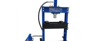
Brief description of the LGSG-28 model
In the equipment of many manufacturing enterprises whose activities involve the need to bend sheet metal workpieces, one can find a hydraulic bending press model LGSG-28, manufactured by the Lipetsk plant for the production of special roll forming equipment. The technical capabilities of such a press make it possible to successfully use it for bending sheet metal blanks, the thickness of which reaches 3 mm and the length up to 2.5 m.
The main purpose of the LGSG-28 sheet bender is to produce corners or channels from a smooth sheet
The most appropriate use of a machine of this model is for those enterprises that are engaged in the production of the same type of metal products in medium and large series. Of the most significant advantages of the press brake of this model, the following should be highlighted:
- low noise level emitted during operation of the device;
- ease of management and maintenance;
- optimal combination of functionality and cost;
- economical energy consumption;
- the ability to perform bending both manually and fully automated;
- high versatility;
- high reliability, availability of spare parts and components for maintenance and repair.
The press brake is equipped with a punch and die made of hardened and ground steel
The hydraulic equipment equipped with the press of this model allows the development of force in the bending area, reaching a value of 20 tons. The maximum bending angle that such equipment can achieve is 105°, and it can be performed at a minimum width of 4 cm.
Using CNC machines in production
CNC sheet bending machines are used for the following purposes:
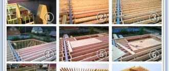
- manufacturing of structural elements for roofing, precipitation drainage systems, snow catchers;
- production of housings for household appliances;
- creating profiles for windows and fencing elements;
- production of electrical equipment: distribution boards, transformer housings, fastenings;
- production of furniture fittings, fireproof cabinets, benches;
- production of specialized parts for industry: protective screens, shields, housings, profile parts;
- manufacturing of car body elements, as well as special equipment.
The presence of numerical program control allows you to automate work and quickly rebuild equipment for the production of various parts. The system adjusts and controls processing, takes into account errors, compensates for the load, and implements energy saving modes.
Vertical hydraulic press brakes. Part 1. Description and general characteristics
We would like to bring to your attention a short series of articles dedicated to vertical hydraulic press brakes. In it, we will tell you about the principles of operation of this equipment, the main parameters that you should pay attention to when choosing presses, about the controls and main components that affect the operation of the press and the quality of the resulting products in general.
There are many options for sheet metal bending equipment on the market, which differ in the type of drive - manual, mechanical, electromechanical, servo presses, hydraulic and the principle of operation - sheet benders with a rotary beam (panel benders), horizontal sheet benders and vertical sheet metal press brakes. But the essence of the technological process for all presses is the same - metal forming. The force transmitted by the drive to the working body of the press allows bending of the metal sheet according to the specified parameters.
Today, “classic” CNC vertical hydraulic press brakes are especially popular in modern production facilities.
Thanks to their fundamental design, sheet benders of this type allow you to perform complex tasks of bending sheet steel of almost any thickness, everything depends only on the force of the press, bending length and opening of the matrix, but we will talk about these nuances in the following articles.
So, let's take a closer look at the design of this equipment using the example of hydraulic presses from the leading Turkish manufacturer - the ERMAKSAN company.
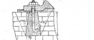
The side stands of the press (1) are part of the frame. They are located to the left and right of the press working area. On ERMAKSAN sheet bending machines, the walls, as well as the entire frame, are made of durable thick-walled steel, because it is on this element of the frame that hydraulic cylinders (5) and it is subject to heavy loads. Hydraulic cylinders are attached to the side walls on milled and ground platforms. This is necessary for a tight fit of the seating surface of the hydraulic cylinder to the installation site, which in turn ensures a strictly vertical position of the cylinder and a more directed distribution of force, and also reduces the load on the frame. An important structural element, located on the side posts, is the so-called “cutout in the frame”, or as it is also called “zharp”. Around the jaw there is a “C-shaped” bracket equipped with a sensor - this simple device allows you to monitor the deformation of the bed when working at maximum effort and protect the machine from overloads. We will talk about the role of the pharynx in the design of the press below.
Zev in a frame with a protective bracket.
Also, the main element that forms the bed of the press brake is the lower front wall (4) , which is welded together with the side posts - the press bed is a powerful, welded structure. In the upper part of the front wall of a vertical press brake there is a work table, onto which all the working force of the machine is directed. Due to the susceptibility of this structural element to heavy loads, it is made of the thickest-walled steel. The main working body of the press, on which the upper bending tool is located, is the upper traverse (6) , which, by moving the hydraulic cylinder rods, moves in a vertical plane up and down, transmitting the hydraulically specified force to the workpiece. This is where the name of press brakes comes from – “vertical”. On ERMAKSAN press brakes, two hydraulic cylinders move the upper crossbar up and down, forming two axes - Y1 and Y2. Positioning accuracy and parallel movement of the traverse along these axes is achieved using optical rulers produced by the German company HEIDENHEIN - this is a significant competitive advantage of ERMAKSAN presses, because optical rulers have higher accuracy compared to magnetic rulers, which are used by third-party manufacturers of press brakes.
HEIDENHAIN optical rulers
There is also a more outdated system that ensures the parallelism of the movement of the upper traverse - a torsion shaft. In this case, two hydraulic cylinders are combined into one axis - Y, which deprives the operator of controlling the parallelism of the beam movement, the ability to calibrate it and, if necessary, skew the beam for certain types of bending. Also, the torsion shaft, like any mechanical unit, has its own natural wear, which negatively affects the accuracy of operation. Today, the use of torsion shafts is justified on equipment with simple control systems (DCS), where high precision of products is not required and the price of the equipment is an issue.
The second most important movable working element of a press brake is the back stop (3) . As the name suggests, this element of the press brake is used to rest the front edge of the part being bent against it. Depending on the specified program and the complexity of the part, the back stop moves in different planes. It is enough for the operator, after each successive bend, to rest the edge of the sheet against the fingers of the back stop and carry out the next bend. On modern presses, the minimum configuration is a design with one controlled axis (X axis - moving the stop back and forth) from the CNC, the remaining axes are set manually by the operator. Depending on the complexity of the press, the back stop can be equipped with six CNC-controlled axes. We will go into more detail about the back stop of the presses in another part.
The top of modern hydraulic press brakes houses the hydraulic oil tank and main drive hydraulic system (2) . On ERMAKSAN press brakes, the hydraulic system is provided by BOSCH-REXROTH and HOERBIGER. Also, as a rule, on the side of the press there is an electrical panel in which the main electrical components of the machine and control units are located. ERMAKSAN presses are equipped with electrical components from world leaders in this field - SIEMENS, PILZ, TELEMECANIQUE, SCHNEIDER ELECTRIC, etc.
Control systems for press brakes deserve special attention. Modern equipment is increasingly equipped with CNC systems. Simple controllers and DROs are becoming a thing of the past. This is due to the availability and convenience of modern CNC systems. At the customer's request, CNC systems from leading European manufacturers - DELEM, CYBELEC, ESA - are installed on ERMAKSAN press brakes. The choice of control system depends on the complexity of the press, production tasks and personal preferences of the customer. We will tell you more about CNC systems for press brakes in another part.
We propose to consider the main technical characteristics of presses and understand what they mean and what to pay attention to. Let's take the ERMAKSAN hydraulic press brake model SPEED BEND PRO 3100-100 as an example.
Technical characteristics of the press:
| ERMAKSAN SPEED BEND PRO 3100-100 | |
| Parameter | Index |
| Maximum force, tons | 100 |
| Bending length (A), mm | 3100 |
| Distance between posts (B), mm | 2600 |
| Pharynx depth (E), mm | 410 |
| Idle lowering speed, mm/s | 200 |
| Working speed, mm/s | 12 |
| Return speed, mm/s | 190 |
| Deflection compensation system | Automatic |
| Maximum stroke and speed of the backgauge along the X-axis, mm x mm/s | 800x500 |
| Maximum stroke and speed of the back stop along the R axis, mm x mm/s | 250x350 |
| Speed of movement of the back stop fingers along the Z1 and Z2 axes, mm/s | 1000 |
| Number of thrust fingers on the back stop, pcs. | 2 |
| Number of front calipers, pcs. | 2 |
| Oil volume, l | 200 |
| Main drive power, kW | 11 |
| Punch stroke (C), mm | 275 |
| Clearance between tables (D), mm | 530 |
| Working height of table (F), mm | 900 |
| Table width (G), mm | 90 |
| Press length (L), mm | 4250 |
| Press width (W), mm | 1950 |
| Press height (H), mm | 2800 |
| Press weight, kg | 6786 |
So, in order:
- Maximum effort. This parameter indicates the maximum operating force of the press achieved at the bottom dead center of the working stroke. It is measured in tons (t) and kilonewtons (kN). This parameter is perhaps the most important.
- Bending length (table length). The second most important parameter determines the maximum length of the bent part. It is measured in millimeters (mm).
- Distance between posts. As we wrote above, the bed is formed by two vertical walls of the press - racks. Due to the design features of hydraulic presses, the distance between the posts is always less than the bending length.
- Pharynx depth. We also wrote about the “cutout in the bed” above. This cutout in the side posts is necessary for bending the sheet over the entire length of the table - in this case 3100 mm. On this press model it is 410 mm. Accordingly, over the entire length of the desktop, we can bend the sheet to a maximum depth (maximum bendable shelf) of up to 410 mm from the center of the matrix to the side posts. At the customer's request, this gap can be increased to 1500 mm - depending on the press model. The distance between the racks on this press is 2600 mm, so if we have the task of bending a shelf of more than 410 mm, then we can make it at a length of no more than 2600 mm. Otherwise, the sheet will rest against the racks.
- Idle lowering speed. This is the same speed as the tool advance. This is the speed of free lowering of the upper beam, without developing a working force.
- Working speed. This is the speed of movement of the upper beam to the lower specified position, with a given force. It is at this stage that the sheet bending process occurs.
- Return speed. Indicator of the speed at which the upper traverse rises to the upper position.
- Maximum stroke and speed of the backgauge along the X and R axes. Speed of movement of the backgauge fingers along the Z1 and Z2 axes . As the name implies, these parameters determine the movement values of the back stop in various planes (axes). ERMAKSAN press brakes of the SPEED BEND PRO series are equipped with high-speed back stops, despite the fact that the back stop is made of steel, not aluminum, like many other manufacturers.
- Number of stop fingers on the back gauge. Indicates the number of fingers on the stop; the press operator rests the front edge of the sheet being bent directly against them. At the customer's request, the number of back stop fingers can be increased.
- Number of front calipers. At the front of the press brake there are movable supports with T-slots and a millimeter ruler that support the sheet being bent. If necessary, the number of supports can be increased.
- Oil volume. Indicates the volume of the hydraulic oil tank. As a rule, when filling the container for the first time, it is necessary to fill in more oil, because This parameter does not take into account the volume of oil to fill the entire hydraulic system.
- Main drive power. This parameter indicates the maximum (peak) power of the main drive. At idle speed, when the equipment is idle, the drive operates at less power and, accordingly, consumes less electricity.
- Working stroke of the punch. The maximum working stroke from the bottom edge of the bending upper tool (punch) to the bottom point of the groove of the lower tool (die). Depending on the tool used on the press (punch length and die height), the working stroke changes.
- Clearance between tables. This is the distance between the edge of the traverse located at top dead center to the press table. This parameter is also sometimes called “maximum opening”.
- Working table height. This is the distance from the floor level to the top surface of the press work table.
- Table width. This is the distance from the front to the back edge of the table. It is worth paying attention to when choosing the lower tool (matrix).
- Length, width, height of the press. Indicators of the overall dimensions of the press in working condition.
- Mass of the press. Indicates the dry weight of the press, without hydraulic oil. It is believed that the heavier the machine, the more powerful it is, has a thick-walled frame, is less susceptible to deformation and vibration, and accordingly has high accuracy characteristics.
In our article, we briefly told you about the main components of a vertical hydraulic press brake and described the general characteristics of the machine. We will tell you in more detail about the most significant organs of the press in the following parts of the article.
is the official representative of the Turkish company ERMAKSAN in the Russian Federation.