The process of heat treatment of volumetric metal structures is based on strictly regulated principles, defined as standard welding process technologies. From this point of view, preparation and supervision of welding is impossible without the use of special analytical methods, which are an integral part of the general work.
Optimization of the technological process of welding metal structures involves several different options for its implementation. For this purpose, practice-tested techniques are used, which boil down, in particular, to the preparation of special accompanying documents (technological maps).
Technological cards
The welding flow chart includes a number of points and graphs indicating the following characteristics of the welding process of metal structures:
- product name;
- units of measurement of the volume of work performed;
- digital code of the operation being performed;
- designation of the standards on the basis of which it is implemented;
- automation level, operator qualification code and many other parameters.
The contents of a typical technological map can be found in the Table
The main purpose of this scientific document is to record all the information about the completed operation for the construction of metal structures and store its codes in a computer database as a standard sample.
Based on these maps, enterprises and organizations prepare and constantly update information arrays that make it possible to quickly refer to a previously implemented technological process.
All information specified in the cards is entered into the database only in encoded form.
When developing a new technology for welding metal structures, it is taken into account after an expert assessment of the effectiveness of upcoming operations is carried out (based on the characteristics of individual prefabricated products).
Quantitative assessment of the manufacturability of these operations is carried out taking into account the following factors:
- the sequence of their implementation;
- breakdown of metal structures into independent technological units;
- types of equipment and special devices used;
- current welding modes, expected stresses in the structure and the degree of deformation of individual components.
Upon completion of testing the effectiveness of the new welding process chain, the data and codes are sent for storage to the enterprise computer database.
Requirements for welding metal structures
The purpose of the created standards is to ensure safety and high-quality installation of structures made of metals and alloys. You should also be guided by them when assembling household products in the country, in the garage, or on farmsteads. Important points:
- ensuring protection of the welder from electric shock , for which it is necessary to protect him from rain, exposure to ultraviolet and infrared radiation, short circuits when connecting equipment;
- proper preparation and assembly of structures - required to create strong connections with the specified characteristics;
- preparation of welding materials and parts - calcination of electrodes, their proper storage, cleaning of surfaces from dirt and rust.
Errors made during assembly and welding of parts can lead to the destruction of metal structures, which poses a danger to people working in close proximity to them.
Assembly of parts
Welding of metal structures prepared in the form of separate prefabricated units is carried out in accordance with GOST 5264-80, which defines the principles of installation based on the electric arc method.
In accordance with the provisions of this document, the procedure for preparing a metal structure for assembly is determined, including methods for supplying its individual elements to the welding site.
The fusion modes of individual components of metal structures are established, which are selected in accordance with the data specified in the previously compiled technological map for this type of welding work.
The final installation of the metal structure is carried out in a certain sequence, including preliminary cleaning of the edges and the areas closest to them. In this case, the fitting of elements for welding is carried out either using mechanical means or through gas cutting.
When assembling an already prepared product, they are guided not only by the drawings, but also by the previously mentioned technological maps. In addition to the operating modes and assembly order, they must indicate methods for fastening parts, as well as methods for monitoring assembled products.
In the process of preparing metal structures, it should be assumed that when welding them, an electric arc is supposed to be used, the melting point of which can reach 7000 °.
The peculiarities of this method of assembling complex objects include the fact that special welding devices are used in its implementation.
04/08/20 942 RPS “Assembly of parts for welding”
In workbooks, prepare the report in the form of a short summary according to the plan (only in bold).
I'm waiting for photo reports of the work done.
After studying the lecture, take the online test.
LECTURE TOPIC:
Boring of parts for welding.
PLAN:
- Types and methods of assembly.
- Assembly rules.
- Types and purpose of assembly, technological devices and equipment.
- Types and methods of assembly.
The labor intensity of assembling parts for welding is about 30% of the total labor intensity of manufacturing the product. To reduce assembly time, as well as to increase its accuracy, various devices are used.
Assembly for welding can be performed in the following ways:
complete assembly of the product from all its constituent parts, followed by welding of all seams;
alternately attaching parts to an already welded part of the product - if it is impossible to use the first method;
preliminary assembly of the units that make up the product, followed by assembly and welding of the product from the assembled units; this method is the most rational; it is used in the manufacture of large and complex structures (ships, carriages, bridges, etc.).
2. Rules for assembling structural elements for welding.
In general, assembly is a set of operations to install parts in the position specified in the drawing for subsequent welding.
The main goal of developing an assembly process is to determine the most advantageous sequence and method of assembling individual parts, ensuring that the technical requirements for the manufacture of a given product are met with minimal labor, time and auxiliary materials. When developing this process, one should strive for maximum mechanization of assembly work through the widespread use of various kinds of power tools, working and control devices. It is necessary to strive to eliminate the operations of fitting, filing, and drilling in place.
Depending on the type of product, certain technical requirements for assembly are established. From a welding point of view, a requirement included in the technical specifications is to ensure certain design parameters of welded joints. Thus, a specific feature when assembling parts joined end-to-end by fusion welding is the observance of certain gaps between the welded edges. The size of the gaps depends on the thickness of the elements being connected and is established by standards or GOST.
When assembling parts with an overlap before resistance welding (TES and RES), a necessary requirement is the complete elimination of gaps. According to the standards adopted in production, these gaps should not be more than 10% of the thickness of the thinnest part to be welded and exceed 0.1 ... 0.5 mm.
The assembly technological process is characterized by a certain labor intensity, as well as a certain time, called the assembly cycle, during which this process is carried out. The complexity of assembly depends on the degree of perfection of the design, the development of the technological process, the degree of interchangeability of the assembled elements and their accuracy, the power supply of equipment and equipment. Assembly cycle:
C = T/p,
where
T is the labor intensity of the process, h;
n
is the number of workers simultaneously employed in the process.
Obviously, the reduction in cycle is influenced by a decrease in labor intensity and especially an increase in performers. The latter depends on the design, scale of production, level of technology and production organization. Dividing the structure into units makes it possible to expand the scope of work, which also increases the number of workers employed in the assembly.
The size of the assembly cycle is greatly influenced by the choice of assembly process scheme. The assembly process diagram is the accepted sequence of assembling assembly units and connecting them into products.
In the production of welded structures, sequential assembly and welding of elements, complete assembly of the entire structure with its subsequent welding, parallel-sequential assembly and welding are used.
The sequential scheme (Fig. 1,
a) is advisable when assembling structures that are not divided into subassemblies, when welding of a fully assembled structure is impossible, and other schemes cannot provide the necessary accuracy due to the design features, for example, due to its insufficient rigidity.
It is performed by sequentially building up individual elements. The required accuracy can be achieved by using intermediate editing operations. Assembly and welding with such an organization of the process are less productive, since when they are performed sequentially, the scope of work is limited and the number of workers is reduced.
Rice. 3.18. Assembly diagrams for welded structures:
I,
II , III, IV— design details; 1-6 - technological operations
The scheme of complete assembly of a structure with subsequent welding (Fig. 1,
b) is usually used for relatively simple products or products of medium complexity, consisting of a small number of parts with easily accessible connections.
According to this scheme, the structure is first completely assembled, securing the elements with clamps, fasteners, and tack joints, after which the assembled structure is transferred to the welding area to weld all connections.
At the same time, the scope of work expands, the C
decreases. The scheme is used for various types of production. The technological process of assembly and welding, depending on the production program, weight and configuration of products, can be mechanized or fully automated.
The parallel-sequential circuit (Fig. 3.18,
c) is used in the manufacture of complex structures, divided into enlarged assembly units.
First, enlarged assembly units are assembled and welded on parallel production lines.
Then the finished units are assembled and welded into entire structures. With this scheme, the number of simultaneously employed workers or the scope of assembly work is much greater, so C
is minimal. Practice shows that such a circuit can reduce the cycle by 3...4 times compared to a sequential circuit. This confirms the great advantages of dissected structures. However, the number of assembly units must be selected based on economic feasibility. When assembling and welding structures, it becomes possible to widely use mechanization and automation of technological operations. With this scheme, the accuracy of manufacturing products increases, and the overall deformations of the entire structure are reduced, since the rigidity of the units is always greater than the rigidity of the individual parts. In addition, it is easier to straighten deformed components than a fully welded structure. This, in turn, helps improve the quality and reliability of products. The scheme is used in various types of production. Thus, by skillfully developing a scheme for assembling products, you can influence the duration of the process and reduce labor intensity.
The content of the technological operations of the assembly processes of structures, in turn, is determined by the methods of basing and assembly used, on which the accuracy and interchangeability of the assembled product, the content of assembly work, and the composition of assembly tooling and equipment depend.
Depending on the type of production, design features and technical conditions, assembly can be performed in various ways: by markings, by templates or the first product, by assembly holes, in fixtures (universal, specialized and special).
Assembly according to markings is carried out without devices. The location of the parts is determined by markings according to the drawing. Then they are secured with clamps, removable clamps, potholders, etc. The productivity of the method is low; it is used in single production for the manufacture of simple products. Achieving the specified accuracy during assembly is possible only with a large expenditure of highly skilled labor. Using templates or the first product to assemble can improve productivity.
Assembling components using assembly holes is a progressive process that allows for high economic performance of assembly work and sufficient accuracy. An obstacle to its widespread use is the design of the connections, which often makes it difficult or completely impossible to use assembly by holes. Therefore, it is necessary to provide for the assembly method already during the structural development of the product and testing its manufacturability. When assembling using assembly holes, the specified arrangement of product parts is achieved by using the holes as assembly bases for parts. Assembly holes serve to coordinate and fix parts of the product and are usually assigned from among the holes included in the connection, which is very rare in welded assemblies. In such products, existing structural holes can be used as assembly holes. Sometimes they can be designed as technological with subsequent removal by welding or riveting (Fig. 3.19, a).
Holes are drilled along overhead jigs. Assembly using assembly holes simplifies assembly equipment, but requires end-to-end coordination of the dimensions of the parts. For thin-sheet elements, instead of holes, special stampings can be used.
The greatest assembly accuracy with minimal labor intensity can be achieved with special assembly equipment, usually used in large-scale and mass production.
Rice. 3.19. Assembly by holes:
A
— panels:
1
— casing;
2
— stiffening element;
3—
latch;
b
— bracket: / — body;
2
— bracket;
3
- latch
In production conditions with a small production program, universal and specialized devices of medium complexity are used.
In addition to assembly equipment, the quality of workpieces has a decisive influence on the labor intensity of assembly work. In the absence of interchangeability of parts, assembly is complicated by the need to perform fitting operations. When performing technological operations, even under conditions of the strictest technological discipline, abnormal side changes occur in the processed objects, many of which can have a significant impact on the quality of the product. For example, deviations in the shape and size of sheet parts due to elastic stresses arising during bending, drawing and other shaping processes, or the appearance of residual stresses in welded parts.
Non-standardized changes in the properties of production objects that occur during the performance of individual operations of the technological process are one of the reasons for the instability of product quality. The presence of such deviations will, first of all, affect the quality of assembly and welding work. There is a need to carry out adjustment operations during the assembly process. The presence of fitting operations is, first of all, the result of the non-interchangeability of structural elements, therefore interchangeability is the most important prerequisite for ensuring high quality of structures in general. A structural element is interchangeable if its geometric and physical parameters are within the agreed tolerances
with the tolerances of other assembled elements. With such coordination, the need to select or modify elements during assembly is eliminated and the assembly of the entire structure is ensured in accordance with the established technical conditions.
When performing assembly work, there are methods of complete, incomplete, group interchangeability and assembly with fitting of parts. According to the first method, assembly is carried out by connecting parts without any selection, adjustment and other additional work, in full compliance with the technical requirements for the product. The required accuracy of parts is determined by the corresponding tolerances on their dimensions. This method is more often used in the serial production of structures whose elements are subject to preliminary mechanical processing.
Assembly using the method of incomplete interchangeability occurs when one of the connected parts of the dimensional chain is modified during assembly operations, when using compensators. This method is widely used in the aviation industry, automotive industry and other industries. By modifying one of the parts or introducing a compensating element, deviations of parts from the nominal dimensions of the dimensional chain are eliminated and the specified assembly accuracy is ensured. This makes it possible to reduce the requirements for the accuracy of all assembled parts and increase the accuracy of the product without resorting to a large amount of labor-intensive manual fitting and finishing work.
The group interchangeability method involves sorting the assembled elements into groups. The tolerance range of each group is 1 /n
part of the total tolerance field of mating parts
(n is
the number of groups). During assembly, parts of only the corresponding groups are connected to each other so that the resulting overall tolerance for assembly dimensions satisfies the specified accuracy of the product. The use of such selective assembly makes it possible to assign wider tolerances to manufactured parts and at the same time achieve high precision designs. The method is used in large-scale and mass production.
Assembly using the fitting method is carried out by individual modification and adjustment of each of the connected parts. The fitting method is used in single, small-scale production, when it is not economically profitable to have complex technological equipment for manufacturing parts with high precision. Assembly is carried out in two stages, preliminary assembly is introduced for the purpose of fitting and assembling parts. Due to the inevitable contamination of parts during fitting work, after preliminary assembly, the assembled product is disassembled and transferred to operations for preparing the surface of parts for welding. Thus, the surface treatment of parts is carried out after preliminary assembly. The fitted and prepared parts are sent for final assembly for welding. The double assembly method is often used in the manufacture of products from thin-sheet stamped parts, in which it is not always possible to ensure their high interchangeability, especially in single production. Double assembly is sometimes necessary in the manufacture of critical products, such as aircraft fuel tanks, to remove chips from the assembled assembly that formed during fitting.
3. Types and purpose of assembly, technological devices and equipment
. For the assembly and welding of columns, beams, racks of complex cross-section, as well as sheet structures made of steel with a thickness of more than 8 mm, devices are used that allow some movement of structural elements during shrinkage of the weld metal.
Devices can be intended only for assembling parts for welding or only for welding already assembled parts. Combined assembly and welding devices are also used.
An idea of the design of assembly and welding fixtures is given in Table. 9.
Electromagnetic stands are convenient for assembling sheet structures, which record the position of the edges of the sheets being welded (Fig. 1). Electromagnetic stands can be used to assemble and weld sheets up to 15 mm thick. The disadvantage of this type of device is the negative influence of the magnetic field on the welding arc during the welding process.
Rice. 1. Magnetic stand: 1 - electromagnets, 2 - sheets to be welded
In the mass production of identical structures, specialized assembly jigs with mechanisms for clamping parts are used. In these jigs, parts are assembled and tacked, then the product is released from the jig and fed to a site or stand for welding.
The assembly accuracy is checked using templates and probes (Fig. 2).
Rice. 2. Tool for checking the quality of assembly: a - angle of opening of the edge, b - right angle, c - displacement of sheets, d - gap between sheets when lap welding, e - gap when welding v-tee and butt welding
Internet resources used:
- https://metallurgu.ru/books/item/f00/s00/z0000015/st032.shtml
- https://osvarke.net/rabota-s-metallom/podgotovka-i-sborka-detalej-pod-svarku/
- https://studref.com/622473/tehnika/sborka_svarnyh_konstruktsiy
Auxiliary equipment
The process of welding metal workpieces involves their volumetric fixation in a given position, which can only be done with the help of additional devices of a special design (conductors).
The conductor can be made in the form of a stand or a frame of any shape, which ensures the reception and fastening of the next workpiece that is part of the mounted metal structure.
Depending on the conditions and technological features of each specific welding process, jigs can have a variety of designs. In a simplified form, these devices have a shape that allows them to form a right angle in the area where metal products meet.
In addition to these fixing elements, welding work with metal structures involves the use of special feeding mechanisms called stocks.
A welding jig is a structure in the form of an L-shaped lifting device used to place workpieces, above which there is a platform with an operator.
Thus, the established procedure for working with stocks, which greatly facilitates the welder’s work, prescribes their use as support structures intended for laying beams or spans to be welded.
Directly above them, a welding portal (platform) with a welder located in it moves along rails laid along the stocks.
The use of stocks when welding metal structures makes it possible to obtain a continuous (solid) seam without interruption from the welding process.
We also note that when fixing small workpieces using an angular jig, a normalized deviation from the intended joining line is allowed (within the limits provided for by the technological process).
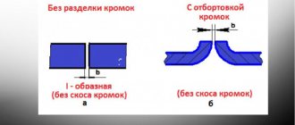
Preparation of weld edges
Preparation of welded edges occurs using both thermal and mechanical methods. Single-sided or double-sided edge cutting can be done simultaneously with two or more cutters positioned at appropriate angles.
Mechanically, the edges are prepared on machines (usually milling), by making chamfers of the desired shape. Mechanical processing can also be performed to ensure the accuracy of the assembly of welded parts. Thermal cutting can be done manually or using software machines.
Features of the manual method
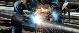
The assembly of building metal structures using arc welding is a complex technological process that only well-trained specialists can handle.
It is based on the thermal effect of an electric arc, for which the main and auxiliary equipment are used.
The first of these components includes a power supply source and a converting power transformer or inverter, and the second includes connecting busbars (wires), as well as a holder with a working electrode.
During manual arc welding of metal structures, current is supplied to the workpieces and electrodes from a converter device, due to which an electric arc is formed. The high temperature in the combustion zone melts the metal, forming a weld pool that remains in a liquid state for some time.
Within the bath, the molten metals of the electrodes and workpieces are mixed with each other, and the resulting slag floats out and forms a protective film.
After the material cools and hardens, a so-called “weld seam” is formed in the bath area. To obtain a beautiful and durable butt joint, it is necessary to comply with a number of requirements regarding both the welding mode and the quality of the arc, as well as the handling technique of the electrode holder.
When assessing the quality of welding, we primarily consider how well the shape of the seam meets a given standard and its visual attractiveness. But no less important is its internal structure, which determines the strength and reliability of the resulting contact.
Metal cutting
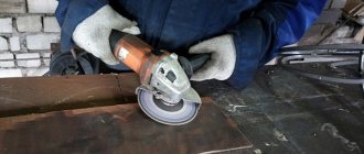
Metal cutting is divided into mechanical and thermal cutting. Mechanical cutting occurs under mechanical influence and is performed on scissors, cutting machines, guillotines, presses, etc.
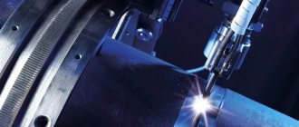
Thermal cutting is carried out due to the thermal effect (melting) of the metal. It can be done manually or by special machines working according to a program. When using such machines, the need for preliminary marking of metal disappears.
Thermal cutting is less productive than manual cutting. But it is much more universal, because... allows you to obtain parts of almost any configuration and any thickness.
Quality control
Particular attention is paid to the quality of welding of metal structures during their assembly, since the slightest deviation from technological requirements can lead to an undesirable result (defect).
The main document regulating the procedure for quality control of welded structures is the manual (set of recommendations or instructions) under the designation RD 34 15.132-96.
This regulatory document, in addition to the list of requirements for welding structures, defines technological standards for assessing the quality of the welded joints formed.
In addition, it prescribes the procedure for carrying out welding work when enlarging existing or installing new metal structures. This guidance document defines the qualification requirements for welding process operators and inspectors, as well as the general procedure for organizing work.
A separate section provides requirements for basic and consumable materials, the use of which ensures high quality assembly and welding of metal structures.
Marking metal for cutting
When marking, the dimensions of the part are applied to the metal. Marking can be done manually, using templates, optically or automatically, using marking and marking machines.
Marking by hand, using templates, is a labor-intensive process and is advisable in cases of single production or small series production. Templates for manual marking are usually made of aluminum. When marking, use a ruler, square, scriber and other tools.
With the optical marking method, the part drawing is projected directly onto the metal surface. Marking and marking machines are equipped with a pneumatic core and mark at a speed of up to 10 m/min with an error of up to 1 mm. They are controlled using programs.
In addition, there are devices for dimensional cutting, as well as thermal cutting machines with photocopying or program control. Such modern machines allow cutting metals without marking at all.
Working with sheet blanks
When considering the technological features of working with sheet products, special attention should be paid to the sequence of welding of workpieces. If there are multidirectional joints in the metal structure being processed, the transverse seams are welded first. And only upon completion of their formation will it be possible to move on to longitudinal connections.
In the process of such work, a welding method should be used in which energy consumption is minimal.
For thin-sheet steel, energy consumption is calculated in units of power per linear meter of the product.
When welding vertically, it is preferable to conduct it in a strictly fixed direction - from top to bottom. In addition, the following rule must be observed: small gaps (at least 1 mm) must remain between the sheet metal workpieces to prevent their warping before welding.
For the same purposes, it is recommended to use special load elements that provide ease of welding of easily deformed sections of the metal structure. The sequence of fusion of sheet blanks must correspond to the order shown in the graphs.
After considering them, we can conclude that welding in this case should be carried out from the middle to the edges.