Tabletop machines Lapmaster-Wolters
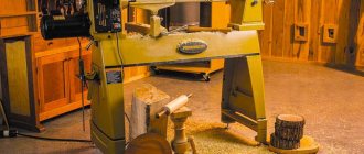
Table-top Lapmaster-Wolters machines are the most popular machine model.
They are small in size but are versatile machines that are ideal for small workshops, workshops and laboratories. Under certain conditions, the machine can be adapted to process larger parts. The machines have direct drive and a welded frame to minimize noise and vibration. Machine feet eliminate vibration. This design is convenient for the operator and simplifies access to the machine for maintenance. The main lapping plate rotates counterclockwise and the forming rings automatically rotate clockwise. The machines work with various abrasive mixtures of various grain sizes, oil-based or water-based.
The machines can be additionally equipped with:
• a device for feeding and distributing the diamond suspension • various lapping plates • water cooling • a pneumatic system for regulating the load on the workpiece • a drive with infinitely variable rotation speed • soft start • parts that come into contact with water can be made of stainless steel.
The machine is delivered fully equipped and ready to work. The machine is controlled from a control panel attached to the machine frame at a convenient height. Lapping plate sizes from 381 mm to 508 mm in diameter.
| Lapmaster 15 - finishing, polishing, lapping table machine with a lapping plate size of 381 mm, which is ideal for small workshops and laboratories. Options: • diameter of the lapping disc: 381 mm • plate rotation speed: up to 70 rpm • diameter of the workpiece: 135 mm • loading weight: 39 kg per workplace (If all three workplaces are loaded, the load of each workplace must be reduced by 50%) • machine dimensions: width – 830 mm, depth – 675 mm, height – 480 mm • machine weight: 140 kg (Including plate and rings) • noise level: 62 dB max. • timer: from 0.1 second to 999 hours • voltage: 400 V, 3 Phase, 50 Hz | Lapmaster 20 - finishing, polishing, lapping table machine with a lapping plate diameter of 508 mm, which is ideal for small workshops and laboratories. Options: • diameter of the lapping disc: 508 mm • plate rotation speed: up to 70 rpm • diameter of the workpiece: 180 mm • loading weight: 53 kg per workplace (If all three workplaces are loaded, the load of each workplace must be reduced by 50%) • machine dimensions: width – 990 mm, depth – 770 mm, height – 660 mm • machine weight: 260 kg (Including plate and rings) • noise level: 63 dB max. • timer: from 0.1 second to 999 hours • voltage: 400 V, 3 Phase, 50 Hz |
Machine for lapping and finishing flat sealing surfaces
During operation, the main components and parts of the valves continuously wear out; to restore their functionality, it becomes necessary to repair the valves. One of the most important technological operations is considered to be the lapping (finishing) of the sealing surfaces of the valve assembly, since this finishing operation allows solving the main problem in achieving the tightness of the valve. The main cause of leakage, the most common one, is poor quality lapping of the sealing surfaces.
The quality of this operation can be assessed by several main criteria: the roughness of the surface being processed, the shape error and the quality of the contact area of the sealing surface, the dimensional accuracy and waviness of the surface, the quality of the lapping and abrasive compounds. The task and main goal when carrying out work to restore the sealing surface is to ensure the tightness of the valve. This condition is achieved through a complete, tight fit of the surface being processed and the lap, as well as the technical capabilities of the tool to perform a certain complex rotational movement.
It is recommended to carry out preliminary and final grinding, depending on the required roughness of the treated surface and materials. In case of significant damage to the parts of the sealing surface or depending on the type, purpose of the fittings and the required tightness class, it is allowed to use an additional finishing operation.
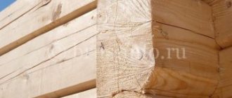
Rice. 1. Example of grinding in wedges of a wedge gate valve
Restoring the tightness of pipeline fittings is an important and labor-intensive process, despite the simplicity of the design, its repair without the use of specialized equipment and accessories is practically impossible, since a number of technological operations and processes are involved that are extremely important to comply with.
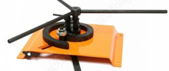
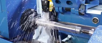
POBEDIT-SPD machine is designed for lapping (finishing) the sealing surfaces of wedges and discs of valves, valve spools (valves) and other flat parts using abrasive paste or abrasive suspension.
Rice. 2. Machine for lapping flat sealing surfaces POBEDT-SPD
The main elements of the machine are:
— device for recirculating the lapping emulsion;
— control panel and electrical equipment;
— holder and separators for processing small parts;
— holder for processing large-sized parts;
— clamping device for static loading of small parts.
Advantages:
— high productivity of the lapping surfaces is achieved by supplying the lapping emulsion directly to the lapping zone;
— the recirculation system, in combination with a two-stage adjustment of the supply of lapping emulsion, makes it possible to reduce the consumption of lapping pastes while maintaining the high quality of the treated surface;
— the electrical equipment of the machine allows for a smooth start of the lapping, as well as control the operation time.
Thus, the use of such progressive solutions, which have a complex translational movement of the tool relative to the surface being ground, will ensure repairs are carried out in an optimal time for the enterprise, with lower labor and economic costs. In addition, by repairing pipeline fittings, it is possible to significantly increase the service life of the fittings and increase trouble-free operation. Repair of valves must be carried out exclusively by qualified specialists who have repair experience, are familiar with the design and purpose of pipeline valves, are equipped with the appropriate technological equipment, tools, and have also undergone production training.
Floor-standing machines Lapmaster-Wolters
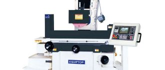
Floor finishing and lapping machines are specially designed to work in harsh conditions and with minimal maintenance.
The machine consists of a welded sectional frame on which a gearbox, electric motor, work table and tanks for abrasive material and waste are installed. Access to the tanks is provided freely by lifting the lid. The lapping plate rotates counterclockwise and the forming rings automatically rotate clockwise. The machines work with abrasive mixtures of various grain sizes, oil or water based.
The machines can be additionally equipped with:
• a device for feeding and distributing the diamond suspension • various lapping plates • water cooling • a pneumatic system for regulating the load on the workpiece • a drive with infinitely variable rotation speed • soft start • additional lapping rings • parts that come into contact with water can be made of stainless steel .
The machine is delivered fully equipped and ready to work. The machine is controlled from a control panel attached to the machine frame at a convenient height. Lapping plate sizes from 610 mm or more in diameter.
| Lapmaster 24 with pneumatic clamps | Lapmaster 36 |
| Lapmaster 24 — finishing, polishing, lapping floor machine with a lapping plate diameter of 610 mm, ideal for all engineering, mechanical workshops and workshops where processing of product planes is an important task. Options: • diameter of the lapping disc: 610 mm • plate rotation speed: up to 70 rpm • diameter of the workpiece: 240 mm • loading weight: 250 kg per workplace (If all three workplaces are loaded, the load of each workplace must be reduced by 50%) • machine dimensions: width – 1100 mm, depth – 1100 mm, height – 1350 mm • machine weight: 550 kg (Including plate and rings) • noise level: 68 dB max. • timer: from 0.1 second to 999 hours • voltage: 400 V, 3 Phase, 50 Hz | Lapmaster 36 — finishing, polishing, lapping floor machine with a lapping plate diameter of 914 mm, ideal for all engineering, mechanical workshops and workshops where an important task is the processing of product planes. Options: • diameter of the lapping disc: 914 mm • plate rotation speed: up to 70 rpm • diameter of the workpiece: 360 mm • loading weight: 300 kg per workplace (If all three workplaces are loaded, the load of each workplace must be reduced by 50%) • machine dimensions: width – 1300 mm, depth – 1300 mm, height – 1100 mm • machine weight: 1350 kg (Including plate and rings) • noise level: 68 dB max. • timer: from 0.1 second to 999 hours • voltage: 400 V, 3 Phase, 50 Hz |
The essence of technology
Lapping, thanks to which it is possible to obtain surfaces with the required degree of roughness and with specified deviations, involves removing a thin layer of metal from the workpiece, for which, in contrast to the finishing operation of scraping, not only tools are used, but also fine abrasive powders or pastes. The abrasive material with which such processing is performed can be applied both to the surface of the part and to a special device called a lap.
Finishing schemes
Lapping, performed at a slow speed and with the help of constantly changing direction of movements, allows not only to reduce the surface roughness to the required value, but also to significantly improve its physical and mechanical characteristics.
Lapping, often called lapping, can be done in a variety of ways. Thus, parts of complex configurations, manufactured in single copies, are processed entirely by hand, and for grinding in products produced in small batches, a semi-mechanical method is used. In this case, the part is fed into the processing zone manually, and the grinding itself is performed using mechanical devices. When producing parts in large series and en masse, one cannot do without a device such as a lapping machine, with the help of which finishing operations are performed.
Hand position when grinding metal surfaces
Classification of metal-cutting machines (page 32)
§ 5. INTERNAL GRINDING MACHINE ZA228
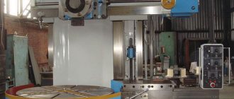
Depending on the nature of their circular feed, internal grinding machines are produced in conventional (simple) and planetary types. Conventional machines are used for grinding holes in parts that can be fixed in a chuck and which can be rotated. Such machines are most widespread. To grind holes in heavy parts, as well as in parts of asymmetrical shape, planetary internal grinding machines are used (see Fig. 111, d).
The ZA228 machine (Fig. 117) is a universal internal grinding machine (simple). It is designed for grinding cylindrical and conical holes.
Characteristics of the machine.
The largest diameter of the grinding hole is 200 mm; maximum grinding length 200 mm; grinding wheel rotation speed 4500–14800 rpm; part rotation speed 85–600 rpm; overall dimensions 3360×1600 X 1930 mm; weight 4975 mm.
The operating principle of the machine is as follows. The workpiece is fixed in a special chuck 1 (Fig. 117), mounted on the spindle of the headstock 2. The clamping is carried out using a hydraulic drive 3. The part receives a rotational movement, and the grinding wheel rotates and reciprocates together with the grinding headstock 4 and table 6, as well as periodically transverse feed along the caliper guides 5
Rice. 117. Internal grinding machine ZA228:
1 - bed; 2 - headstock of the product; 3 - grinding wheel. 4 — spindle of the grinding head; 5 - grinding head; 6 - table. 7 — controls.
The main movement is
rotation of the grinding wheel is carried out from an electric motor (N = 4.5 kW, n = 2900 rpm) through a flat belt drive with replaceable pulleys.
Circular feed -
rotation of the workpiece is carried out from a direct current electric motor (N = 1.1 kW, pm = 1000 rpm) with stepless control of the shaft speed through
80 V-belt transmission -
Longitudinal feed -
reciprocating movement of the grinding wheel is carried out from a hydraulic drive with hydraulic cylinder 7. The table speed is infinitely adjustable within the range of 0.1–12 m/min.
The table receives manual movement from the flywheel 8 through gears
18 18 wheels —,— and rack and pinion pair (z = 18, m = 2.5). Guide-
Fig. 118. Kinematic diagram of the ZA228 internal grinding machine
The hydraulic and manual movements of the table are interlocked. When carrying out hydraulic supply, the rack wheel z = 18 is disengaged from the rack with the help of hydraulic cylinder 9. Fine longitudinal feed of the grinding wheel when grinding ends
carried out manually with a flywheel 19 through a worm and screw pair
with a step P = 4 mm. In this case, the table first moves from the hydraulic cylinder 7 until the moment when the cam 21, fixed on the table, rests against a fixed special end stop 20. Then the table stops, and the grinding head moves from the flywheel 19.
Cross feed of the grinding wheel
can be manual (continuous or dosed) or automatic from a hydraulic drive. Manual continuous
21 feeds are carried out using a flywheel 10 through gears - and
63
screw pair with a pitch of P = 6 mm. Dosed manual feed
is done by swinging lever 12 through
17 17 21
ratchet gear (z = 200), gears —,—,— and screw pair (P
34 68 63
= 6 mm). For both types of manual feed, automatic feed from the hydraulic drive is switched off with button 13.
Automatic cross feed
is carried out from cylinder 11 when button 13 is turned on (the button engages the pawl with the ratchet wheel z = 100). When oil enters the right cavity of cylinder 11, its piston, through the rack flap, transmits movement to the rack wheel z = 22, from
21
which through the ratchet wheel z = 100 and transmission - receives rotation
63
cross feed screw with pitch P = 6 mm. Reversing the longitudinal and transverse feeds is carried out by stops.
To compensate for wheel wear when working in the “fit to size” mode, there is a special mechanism. Using button 14, through the gear wheel z = 32 and the gear sector z = 128, set the cam 15 to the position corresponding to the specified compensation. When the required size of the hole to be ground is reached, the axis 16 of the pawl will move onto the cam 15, disengage the pawl from the ratchet wheel z = 100 and the feed will stop.
Fast retraction (rebound) of the grinding wheel
from the surface to be treated, when the specified size is reached, before the wheel is removed from the hole, it is carried out by a hydraulic cylinder 17, the piston of which is connected to the cross-feed screw of the grinding headstock. The amount of retraction is set by screw 18. The machine has a device for dressing the wheel and can be equipped with a face grinding device for grinding the ends of parts with a special wheel.
Chapter XIX
FINISHING MACHINES
Finishing machines are designed for final fine processing of parts, which consists in removing small irregularities - ridges left during previous processing. The most widely used finishing machines are machines for honing, lapping and superfinishing.
§ 1. HONING MACHINES
Honing is performed with a special tool using a honing head (honing head), equipped with fine-grained abrasive stones (Fig. 119). The head performs simultaneous rotational and reciprocating movements in a stationary hole. By honing, you can obtain a high-quality surface, as well as correct some hole defects (tapering, ovality, etc.). When honing, emulsion or kerosene is used as a cutting fluid.
The bars 4 of the honing head receive radial movement using cones 2 and 5 mounted on the rod 3
Rice. 120.
Vertical
hoshpp oval machine:
1
- bed;
2
- column;
3 — electric motor of the main movement; 4 -
movable carriage 5 - workpiece
6 -
table
Rice. 119. Honing head
with a screw thread, and having the ability to approach or move away from each other when the rod 3 rotates. When approaching, cones 2 and 5 move the abrasive bars 4 apart through fingers 1, and when moving away, they move. Thus
The bars are set to the required diameter before processing begins. With an automatic honing head, the radial movement of the bars 4 to enable self-installation in the hole being machined is carried out automatically, for which the head is connected to the machine spindle with universal joints. After each double stroke of the head, rod 3 rotates and brings cones 2 and 5 closer together.
Depending on the type of processing, honing machines are divided into machines for honing holes and external surfaces, and according to the location and number of spindles - into vertical and horizontal, single and multi-spindle. The general view of a vertical honing machine is shown in Fig. 120.
The spindle rotation of honing machines is usually carried out by an electric motor through a mechanical gearbox. The reciprocating movement of the spindle on vertical honing machines is usually carried out using a hydraulic drive. In horizontal machines, an electromechanical, rope, chain or hydraulic drive is used for this.
§ 2. GRINDING MACHINES
Principle of operation.
Lapping is carried out using laps, onto the surface of which a fine-grained abrasive powder mixed with a lubricant or paste is applied. Lappings can be cast iron, steel, bronze, lead, hard wood, etc. Emery, electrocorundum, diamond dust, silicon carbide, etc. are used as abrasive powder, and chromium oxide, aluminum oxide, crocus are used as paste , Vienna lime, etc. During grinding, the abrasive powder is moistened with kerosene or turpentine. The lapping allowance is left approximately 0.005-0.02 mm.
On lapping machines, you can process various external and internal surfaces, including flat ones, lap crankshaft journals, camshaft cams, end blocks, gauge plugs, gears, etc. In Fig. 121 shows a diagram of a lapping machine. The lapping drive 5 is placed in the frame body 1. The lapping 3, connected to the machine spindle placed in the column 2, receives rotational and vertical movement.
The grinding of parts occurs with laps 3 and 5, between which a separator 4 is placed. The parts to be processed are freely placed in the nests of the separator, which is located either eccentrically relative to the axes of the laps, or concentrically.
Fig. 121. Diagram of a lapping machine operating with metal discs
Rice. 122. Separator disk
In the first case, the separator is free
mounted on an axis that rotates in the direction of lap 5. In the second case, the separator receives an oscillatory reciprocating motion from a separate drive.
The separator disk (Fig. 122, a) has transverse movement to change the eccentricity of its axis relative to the axis of rotation of the metal laps; this is necessary to ensure even wear of these laps. An approximate relative trajectory of a part during processing is shown in Fig. 121.6
Universal lapping machine 3816
(Fig. 123). The machine is designed for processing flat and cylindrical surfaces.
| Due to the large volume, this material is placed on several pages: 32 |