Glossary
LED strip, SDL – LED strip.
RGB strip is a multi-colored LED strip.
LED element, crystal, LED - light-emitting diode (diode).
A resistor is an element of an electrical circuit that limits the operating electric current.
Dielectric is a material that does not conduct electric current.
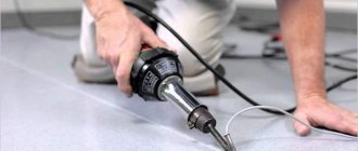
A soldering iron is a tool designed for soldering and tinning when heated.
The tip is the tip of a soldering iron that applies solder.
Pole is a certain side (direction) of a constant current source, “plus” and “minus”.
Stripper is a hand-held tool for stripping cable insulation.
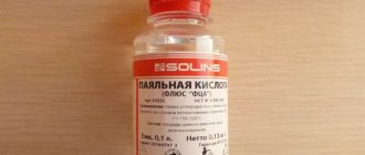
Rosin, flux, is a substance that cleans the surface from oxidation.
Solder is a substance used for soldering.
Tinning is the process of covering a work surface with a thin layer of solder.
A connector is a device for connecting sections of an LED strip to each other, without solder.
Typical breakdowns
Since you have decided to repair an LED light bulb with your own hands, it is assumed that you have a tester or multimeter and you know how to carry out basic measurements. You will also need a soldering iron, but with a thin tip and low power. You can do without it, but you will have to look for a replacement. You also need to know at least a little how to solder with a soldering iron. You should also have tweezers, wire cutters and utensils. Utiki or duckbills are hand tools that look like miniature pliers with long grips - they are convenient for holding small parts, but you can get by with tweezers. And also spare parts. They will have to be purchased as the malfunction is identified. It's good if there is a second non-working lamp. It can be used as a donor to take the necessary parts from there.
What and where to solder in the LED strip
LED strip (LED) is a light-emitting electrical structure in the form of a flexible printed circuit board (tape) with light sources evenly applied to it - light-emitting diodes (LED) and electric current limiters - resistors (resistors).
When is soldering needed? Example: when contour lighting a ceiling, it is necessary to lay the SDL at a right angle. Despite the flexibility of the board, an ideal right angle can only be achieved by connecting its two parts. Therefore, it is cut into 2 parts in a place specially designated for this purpose, so as not to break the connection diagram of the crystals.
SDL cut location
After this, work on connecting the SDL begins. The complexity of the soldering process depends on the type (single-color, multi-color), type (open, sealed) of the tape, the number of current-carrying paths, and the use of additional devices.
Recommendations for work
When soldering the diode strip to other components of the lighting system, you must adhere to the following recommendations:
- follow the soldering instructions given above exactly;
- qualitatively isolate the work area;
- follow the soldering diagram to connect everything correctly;
- avoid overheating the product while working with a soldering iron;
- use high-quality components of the system - power supply, controller, tapes.
If you follow the above recommendations and step-by-step instructions, soldering the LED strip will be easy and simple. In addition, it is necessary to follow the rules for working with heating tools and electrical appliances, especially when checking their functionality. If you follow all the recommendations, then soldering the strip with LEDs will not be difficult at all.
How to solder together
It is possible to solder two sections of tape together (to build up) in two ways:
- Using connecting wires. Each line connects equivalent contacts of two boards (plus with plus, minus with minus).
- Overlapping connection. The connection occurs by overlapping sections on top of each other and soldering them at the contact pads.
- If the SDL is long, it is connected in parallel to the common bus using connecting cables.
Soldering wires to tape
- Clean the ends of the connecting wires using a utility knife or stripper. Tighten the exposed (bare) parts slightly.
Stripped connecting wire
- Tin open ends. Solder is taken to the end of the soldering iron. The end of the cable is dipped in rosin and then solder is applied with a soldering iron. For uniform coverage, the process is repeated 3-4 times.
The process of tying up ends
The length of the cable (up to 2-3 mm) is selected so that its bare ends lie exactly in the “cups” of the contact group. An end that is too long can cause the plus and minus contacts to short out.
- Tin the contact pads of the LED strip:
- Use the end of a toothpick to apply flux to the contact pads.
Applying flux to contact pads (nickels)
- Using a heated soldering iron, apply solder to the contacts by briefly pressing (up to 2 seconds). The maximum contact time between the SDL and the soldering iron is 5 seconds. It is important not to short-circuit the contacts when applying solder.
Applying solder to pads
- Solder the connecting wire to the SDL. Its end is applied to the contact pad of the board. Then, with a short, gentle pressure, solder is applied from above with the tip of a soldering iron.
Due to the high temperature, the tin melts and the wire sinks into the contact “cup,” thereby guaranteeing a reliable connection protected from oxide.
Solder the connecting wire to the SDL
- Solder the second wire in the same way.
Solder the second connecting wire to the SDL
Overlapping connection without wires
- Tin the contacts of one of the tapes on both sides:
- remove the required distance (up to 2-3 cm) of the adhesive base from the back of the board;
- clean the back surface of glue;
- tin the contact pads on the working and opposite sides of the board.
The process of sealing contacts when connecting a board with an overlap
- tin the contacts of the second tape on the working side.
- Place the “back contacts” of the first tape on the contacts of the second tape located on the work surface.
The process of connecting two boards with an overlap (step 1)
- The upper contacts of the first tape, which should be on top of the structure, are heated with a soldering iron. The holding time of the soldering iron in this case is longer (4-5 seconds), because it is necessary to melt both boards together.
The process of connecting two boards with an overlap (step 2)
This connection is not reliable. It is better to use connecting cables.
Installation of 220V power supply
If you have not completed electrical installation work, then you must first supply 220V voltage to the connection point of the tape. To do this, ditch the wall, or lay a cable channel and stretch a three-core cable VVGng-Ls 3*1.5 along it. Lead it directly to the distribution box where the power supply for the LED strip will be connected.
You can use the existing junction box where the main lighting is connected. The main thing is that the space allows you to freely connect additional wires and terminal blocks.
It is advisable to install the switch on the LED strip on the 220 Volt wires, and not in front of the strip on the outgoing 12-24V. In this case, the unit will not work continuously. Moreover, it is contraindicated for pulse units to operate without load. In addition, this will increase the level of security.
Pre-check and do not confuse phase, neutral and ground. Most often, the neutral is blue, the grounding conductor is yellow-green, and the phase conductor is of any other color. But you can’t trust color coding alone! More details on how to distinguish zero and phase without errors can be found in the article “How to determine phase and zero in electrical wiring.”
Next, you need to lay a cable from this junction box in a groove, corrugated sleeve or in a cable channel to the future location of the power supply. To place it, install a convenient shelf. It can be made from pieces of plywood or drywall. Place a dimmer nearby.
Soldering silicone coated tape
- Stripping the tape from silicone insulation.
Using a utility knife, cut the silicone across the board at a short distance from the contact group. The cut should not be deep so as not to damage the current-carrying path.
Break the cut area and remove a piece of silicone.
The process of cleaning SDL from silicone
- Consistently repeat the process of “soldering wires to tape” or “overlapping connection without wires.”
- If the SDL protection level requires a silicone coating, it is necessary to restore the protection using heat-shrinkable tubing, silicone or glue.
Educational program for beginners
To desolder a part from a board, you need to make sure that the contacts are heated until the solder melts (approximately 230 °C). The main mistake beginners make is to immediately heat the place where they are soldering to 300 - 350 °C.
For example, you need to desolder a microcircuit from a board using a Lukey 702 soldering station.
Many radio amateurs and electronics engineers set heating parameters above 300 °C.
At the first moment, the part is exposed to about 200 °C. The contacts and the surrounding area of soldering work are at room temperature. The heating of the part reaches 300 °C, but the contacts have not yet reached 200 °C. The microcircuit reaches a critical temperature of 350 °C. Meanwhile, the surrounding soldering area is heated unevenly, even if the hair dryer is evenly moved across the soldering area. A noticeable temperature difference of 400 °C appears at the contacts of the part and the microcircuit begins to fry. A little more, and it will unsolder due to the fact that the contacts have practically heated up until the solder melts. But this happens because the board has warmed up. And in this case, it happened unevenly. High temperatures lead to thermal breakdown of the microcircuit and it fails. The board bends, turns black, and bubbles appear due to boiled PCB and its components.
How do you solder parts without damage?
It is necessary to analyze the soldering area and equipment:
Estimate the thickness of the board. The thicker the board, the more difficult and longer it takes to warm it up. The board consists of layers of tracks, masks, pads and many metal parts that are very heat-intensive.
- What's nearby. To avoid damaging surrounding components, they must be protected from temperature. The following will cope with this task: thermal tape, aluminum tape, radiators and coins.
- What is the ambient temperature? If the air is cold, the board will have to be heated a little longer. Of particular importance is what is located under the board. No need to solder on a metal plate or on an empty bench. A wooden board or a set of napkins works best. And at the same time, the board must be in the same plane, without distortions.
- Equipment. Many soldering stations are sold without calibration. The difference between the temperature shown on the indicator and the actual temperature can reach either 10 °C or 50 °C.
Soldering wires at an angle
This scheme is used when it is necessary to connect sections of SDL in parallel to a common supply bus.
Parallel connection of SDL sections
Figure 104 - example of parallel connection of SDL sections
When connecting the cables in series to the ends of the board module and then bending them towards the bus, the distance between the sections of the tapes increases, which will not look aesthetically pleasing during its operation.
Conventional diagram of parallel connection of SDL sections when connecting cable lines in series to the ends of the module
To do this, solder the wires at an angle:
- The wire is soldered at right angles to the contact, which is located closer to the power bus.
Solder at an angle (step 1)
- When connecting the second cable in the same way, the current-carrying parts overlap, which can lead to the contacts closing together.
Solder at an angle (wrong location)
To avoid a short circuit, the second wire is soldered to a contact that was located on the board earlier and belongs to the same group of diodes.
Solder at an angle (step 2)
LED RGB strip
The peculiarity of RGB tape is the contacts located close to each other. When carrying out work on wiring contacts, care must be taken not to close them together with tin tracks due to the short distance.
To do this, use the following methods to reduce the area of the tip (tip) of a soldering iron:
- Sharpen the existing tip using a file. The process is labor-intensive and not rational, because the tip will be damaged and may not be suitable for other jobs.
- Self-production of a tip from a copper cable core with a cross-section of 1-2 mm. Such a tip is attached to the main structure with a bolted connection or a collet connector, depending on the modification of the soldering iron.
A small area of the core will allow you to apply tin more accurately and accurately, but it can lead to rapid overheating of the device.
- Purchase ready-made tips of the required shape and cross-section. If you frequently solder SDLs, this is the most profitable method.
RGB LED strip contact strip
For parallel connection of SDL, each cable is also soldered at an angle to one contact on the module.
How long will it be shining
How can you roughly calculate how long a particular battery-powered LED strip will work and which batteries are best for it?
First, you need to find out the name of the strip itself and what LEDs are used in it. Type this brand into Google and look for parameters.
The most important thing is the voltage and current consumed by the LED.
Let’s say the current consumption of one RGB strip LED when one channel is operating (red glow) will be 18 mA. If all 3 colors are working, then the current already reaches 54mA.
Next, calculate how many of these LEDs will be in your backlight. And multiply this current by their number.
For example, with 50 diodes and the tape glowing at maximum power, the total current consumption will be 2700 mA.
Quite a significant amount. This current can be produced by 18650 rechargeable batteries. For a 12 volt backlight, you will need to collect at least 3 of them in the store.
The 18650 battery capacity in the most popular models is 2600 mAh. There is more and less. These numbers mean that this backlight, powered by 18650 batteries with a current consumption of 2600mA, will glow continuously for about 1 hour.
If the current consumed exceeds the rated discharge current of the battery, the tape will burn for a significantly shorter period of time, and vice versa.
Just remember that for small batteries, it is not recommended to exceed the discharge current by more than one and a half to two times its capacity.
Otherwise, the batteries will quickly deteriorate.
Common mistakes when soldering LED strips
- Heating the soldering iron above 250 - 300 0C.
High temperatures will cause the contacts to overheat and peel off from the board. You can determine the high temperature of a soldering iron tip in the absence of a regulator by the following signs:
- smoke coming from a soldering iron;
- when the tip is dipped into rosin/flux, it boils;
- poor solder connection to the tip;
- black carbon deposits on the soldering iron tip;
- the surface of the solder on the soldering iron tip is loose and matte (there should be a silvery sheen).
- Use of soldering acid and/or active flux
One of the negative properties of acid is the erosion of the area around the contact group.
Active flux has a long reaction (interaction with metal occurs even after soldering), and therefore requires rinsing off.
This has a negative effect on the contact group and can lead to disruption of its conductive properties.
- Use of low-quality LED strips.
Often, counterfeit SDLs use non-copper alloys that are not soldered.
- The use of rigid multi-core cables that do not have reliable solder fixation.
Main conclusions
Soldering SMD LEDs is not very difficult, but requires care and caution. You should remember the danger of overheating of the elements, which will result in their failure. It is necessary to ensure compliance with the following conditions:
- use a low-power soldering iron with a heating temperature no higher than 260°;
- use high-quality flux (experts recommend a special composition for soldering aluminum);
- limit the contact time of LEDs with the soldering iron tip.
In addition, you must remember to maintain polarity and monitor the condition of the current-carrying paths. Please share your options for soldering SMD LEDs in the comments.
Previous
LEDs 12 V step-down transformer: how to choose and connect correctly
Next
LEDs Why and how hot LED lamps get
Connection methods: soldered, connector and clips
- Soldering involves using solder and heating it under the high temperature of a soldering iron to firmly connect the contacts to each other or to the cable.
Soldering is the most reliable method, and the tin-lead composition protects exposed conductive parts from oxidation and overheating.
Its disadvantage is its low mechanical strength; for this purpose, the solder area is protected with heat-shrinkable tubing or silicone.
- Clips. SDL sections are connected sequentially into only one line. The device consists of a small box with metal conductive clamps, which are installed to equivalent contacts of the modules and clamp them together.
- A connector is a device designed to connect sections of SDL to each other without the use of soldering.
Connector example
Connectors can be with or without connecting wires (for overlapping connections), various shapes of connectors (T-shaped, angular, straight).
Types of connectors
Connector or solder?
- The connector is convenient in the following cases:
- when soldering is not possible. For example, when assembling SDL directly under the ceiling. Soldering by weight is a dangerous activity, which can lead to burns as a result of dripping solder and damage (burn-through) of the ceiling covering.
- When changing design. The SDL is easily disassembled into sections and assembled according to the required sketch, thanks to the variety of connectors.
- When working with moisture-proof tape, it is recommended to use soldering, because it provides complete protection and insulation from moisture.
- Related Posts
- DRI lamp (metal halide)
- Let's talk about different types of pool lighting and its beautiful implementation
- Eliminating the cause of blinking and flickering LED lamps
Discussion: 2 comments
- Oleg:
Thank you for the information provided. By the way, who knows where is the best place to buy a New Year's garland? With just over a month left until the New Year, it’s time to think about decorations in the house