08/20/2021 Optical fiber (OF) welding is an advanced technology for permanently connecting fibers during the construction of fiber-optic communication lines (FOCL) and fiber-optic data transmission networks. It is possible to splice single-mode and multimode optical fiber of all types and standards.
Modern welding machines provide minimal losses at welded joints, within 0.01 - 0.02 dB. The combined low attenuation on OB connections allows high-speed traffic to be transmitted over long distances over a fiber-optic line consisting of many cable sections.
All about optical fiber splicing
High-quality welding of fiber optics is possible only with the correct fiber preparation procedure and the use of high-tech equipment from trusted manufacturers.
The catalog of JSC "Component" presents high-tech welding machines for optics of the best quality and at affordable prices.
Welding fiber optic cable
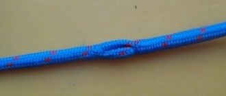
Optical cable welding is the joining of fibers by high-temperature processing. Optical fiber for transmitting light pulses is made of transparent material: glass, plastic, polymers. Information is transmitted by reflecting a beam of light from the walls of the fibers at high frequency. Therefore, the more accurately the light guide is made and the more transparent the material, the better the signal transmission.
The physical principles of the passage of a beam through a conductor will be discussed in more detail in another material. In this article we will discuss how to connect an optical conductor without losing the passage of a light pulse at the joint. As noted above, the conductor is made of fragile material (thin glass core), so working with an optical cable requires high precision and concentration.
Fig 2. Optical fiber: 1 – in a free buffer, 2 – in a rigid buffer.
Fiber optic cable welding steps
Optical fiber welding is divided into several stages - preparatory, welding itself and the connection isolation stage.
- The preparatory part includes:
- Cutting and cleaning fiber from external insulation;
- Removing conductor modules from internal insulation;
- Removing varnish and grease.
2. Second part:
- preparing optical fiber for connection;
- preparing the welding machine.
3. Third stage:
- Fiber connection;
- Joint insulation.
Fiber optic cable
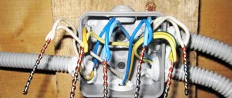
Splicing fiber optics requires an understanding of how the cable containing the optical fibers is constructed.
- Central power element . Gives rigidity to the entire cable.
- Optical fibers . The thinnest threads, which, in fact, need to be welded.
- Tube modules made of plastic . Each module contains several optical fibers. The color of the tubes depends on the preference of the manufacturer, but information about this should be included in the product passport.
- Film . Plays a protective role.
- Polyethylene shell . Provides additional protection in the field of waterproofing.
- Armor . It can be made from rectangular rods or from wires with a round cross-section. Their presence allows the cable to withstand significant breaking forces.
- Outer shell . Made from polyethylene.
There may be slight differences between manufacturers.
Fiber Splicing Equipment
It becomes clear that without special equipment it will not be easy to make a high-quality connection. The industry produces a ready-made set of tools. Usually this is a plastic or aluminum case that includes everything necessary for the work: a machine for welding an optical cable, a cleaver, a liquid for removing grease from the fiber, a lint-free cloth, a stripper (tweezers) for removing insulation. You can purchase equipment separately at specialized dealerships.
Optical line repair
FOCL repair consists of the following steps:
- finding the location of the optical line break;
- organizing repairman access to damaged optical fibers;
- optical cable repair;
- re-checking the cable route.
As stated earlier, the break point is looked for using a reflectometer. Signal loss can occur either in one of the cross-connects or couplings, or in the middle of an entire cable section (for example, underground work at the cable laying site).
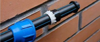
fiber-optic connection coupling
In the first case, the place of the poor-quality seam is broken and a new welding of the optics is done. In the second case, everything is much more complicated; repairing the optical fiber is impossible. If technical reserves and the particular location of the cable allow it, then an additional coupling is installed at the break point. Otherwise, the entire cable section is changed, welding work is carried out at both ends of the new cable. Repairing fiber-optic communication lines is a very expensive process, so it is better to carry out high-quality installation work in advance.
Cleaning the conductor
Before placing the fiber into the splicing machine, the first thing to do is to strip the fiber approximately 40 mm. If you can’t get 40 mm straight away, you can remove the insulation in parts. It is better to carry out stripping with special pliers - a stripper, using holes for the corresponding diameter of the wires. After removing the insulation, the fiberglass is cleaned of grease using a lint-free cloth soaked in industrial alcohol.
Attention! When working, it is necessary to observe safety precautions; if there are broken pieces of fiberglass, they cannot be thrown away, only special disposal.
FOCL welding technology
The length of the optical fiber is measured, it is produced in coils. Multi-kilometer long fiber-optic transmission lines are created by two types of connections:
- detachable;
- one-piece.
Detachable ones require additional costs; connectors and adapters significantly reduce the light transmission of the signal. More often, permanent connections are made by welding fibers with special devices.
Necessary tool
High-quality installation of fiber-optic lines is impossible without two devices:
- cleaver, an apparatus for optical fiber, allows you to cut the cleaned cable strictly at a right angle;
- reflectometer or tester, it determines the accuracy of the connection.
Tools are needed to strip the insulating sheath. A standard soldering kit will do the job. There is everything there: wire cutters, pliers, solvent or alcohol, special thick wipes for removing the waterproof layer. The reliability of the connection depends on the quality of surface cleaning.
Fiber optic cable tool
Preparatory work
The process of preparing the cable before refilling takes a lot of time. First, the optics are examined. Water destroys the light-conducting layer. If the end of the wire is wet, cut off at least a meter from it with a wire cutter. To remove the sheath, the cable is stripped down to a hydrophobic gel. Cutting with a stripper knife does not take much time: after a circular cut at a distance of at least 3 cm from the end, it is enough to pull the cable together. The waterproof layer is removed with a solvent and lint-free wipes. It is necessary to remove the insulation completely, this affects the quality of the chip.
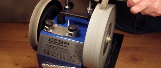
Optical fiber cleaver
A very important tool is the cleaver. The working part of the device is a diamond disk that cuts the fiber at an angle of 90°. The prepared fiber is placed in the cleaver in such a way that there is approximately 16 mm from the edge of the insulation to the cut level. Control using a special measuring scale on the body. The wire is then secured with a clamp. The operation itself is performed by simply pressing a button. The same operation must be done with other conductors.
Attention! Before the chipping operation, you need to put on a thermal insulating tube KDZS for subsequent fixation and insulation of the conductor joint.
Cable cutting and cleaning
A stripper knife is used to remove the outer shell. It has rotating blades that can be used to cut off the outer layer. If the cable is self-supporting, then the cable is removed with cable cutters.
The inner shell should be removed with a specially adjusted stripper knife.
Threads, film, hydrophobe and other elements are removed from the modules. D-Gel solvent is used to remove the hydrophobe. You need to wear gloves when working; the gel is difficult to remove from your hands. Then the modules are wiped with disposable lint-free wipes with solvent, then with alcohol.
At the required distance, the modules are cut with a stripper and removed, leaving the fibers bare. At this stage, fiber optic failure often occurs. The welder needs to work extremely carefully .
The length of the optical fiber without sheaths is usually 1.5-2 m; this is required by the instructions for installing the couplings; welding and installation make the work easier.
Fibers must be handled with care. Any damage at any stage of the work leads to the fact that everything has to be done all over again. Before welding, the optical fibers are wiped with 3-4 dry wipes, then a new wipe is moistened in alcohol and wiped clean.
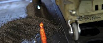
A heat-shrinkable tube is put on the cable for subsequent sealing of the entry into the coupling. When the cable is welded and laid in the coupling, the tube is shrinked using a torch.
The cable is inserted into the coupling, secured, and you can begin measuring the required length of the optical fiber and stripping it. Then a KDZS heat-shrinkable tube is put on it, which will further protect the welding site.
The bare, cleaned end of the optical fiber is inserted into the cleaver. The device cuts the fiber so that the end should be at an angle of 90 ° to the central axis. The permissible error is no more than 1.5 °.
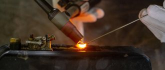
Production of welding works
For this, a special welding machine is used. The procedure for performing the fiber connection operation is approximately the same for all types of machines:
- After switching on, the clamp cover opens, the prepared 16 mm conductor is laid along the installed limiters, with a gap of 1-1.5 mm. to the junction. This operation requires visual control;
- Close the lid and press the start button. The connection process occurs automatically with the process displayed on the monitor screen.
- At the end of the connection, signal losses at the junction are automatically determined; a decrease in the level by 0.022 dc (Decibel) is considered a good result.
Then the KDZS protective tube is placed over the joint. To heat the heat-shrinkable tube, the welding device has a special compartment - a heat stove, where the “raw” insulation is placed. After warming up (about 40 seconds), the device gives a ready signal - you can take out the finished cable sheet. The process of joining fiberglass is clearly shown in the video.
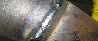
Weld quality check
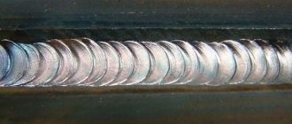
During the welding process, it is necessary to pay attention to the shape of the weld arc. Perfect welding is almost invisible to the naked eye
If the arc is crooked, it is recommended to chop off the weld and repeat the work again.
If the welding machine produces significant signal attenuation at the seam site (more than 0.1 dB), then it is better to digest the fibers. But even if the signal loss is insignificant, the total of several welds can still result in signal loss at the other end of the cable.
Reflectometer
The attenuation of the entire optical path, consisting of several couplings and cross-connects, is checked using a reflectometer. This is a measuring device that sends a pulse along an optical path and analyzes its scattering and reflection. With its help, you can see the total length of the path and the signal attenuation in a separate section. This way, it is possible to find out exactly where the fiber optic cable is causing a signal break or significant attenuation. The instrument saves measurements in an electronic file, allowing dispersion analysis to be carried out some time after testing.
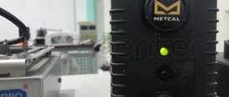
Greenlee 915FS-KIT1 is a kit of equipment for complete installation of optical cables.
The splicing machine included in the Greenlee 915FS-KIT1 kit is equipped with a system for aligning fibers along an active V groove. Provides high quality connections with minimal losses at the connection point. Adaptation to FTTx and PON and the ability to install Splice-On connectors. The welding machine is recommended for installation of fiber-optic lines throughout the city, networks of industrial enterprises, operators and Internet providers.
Figure 3. Greenlee 915FS-KIT1 Fiber Splicing Kit
Features and benefits of Greenlee 915FS-KIT1
- 3 years warranty;
- optical alignment along the active V-groove;
- low losses at the welded joint: 0.02dB;
- automatic and manual arc calibration;
- possibility of installing Splice-On connectors SC, LC, FC, ST;
- protection against water and dust: IP52.
You can see how the device works by watching the video below.
Selecting a welding machine
The degree of signal attenuation and the quality of the communication line depend on the method of cable connection. A reliable seam is possible when the ends of the wire are precisely aligned, so preference is given to devices that align the fiber centrally. The optical fiber splicing machine is selected according to the following parameters:
- modifications of the welded fiber, preferably universal models;
- adhesion speed takes into account the number of connections over a certain time interval;
- cable alignment method;
- configurations
Multifunctional complex devices do not always justify themselves. Chinese models are much cheaper than Japanese ones, and the quality of wire welding is comparable.
Fiber Optic Cable Splicer
Optical cable connection without welding
Expensive optical cable welding operations are included in the cost estimate for large-scale types of major or current repairs. But if you have to repair networks after one-time damage or moving equipment. One of the alternative methods to a welded connection is an adhesive connection through connecting connectors.
The current opinion that gluing is of inferior quality is not correct, because and in both cases, the criterion is the quality of all stages of work performed. The main disadvantage of gluing is the significant increase in time required to complete the work. because the glue must dry well before use.
The process of preliminary fiber preparation is the same as for welding: cleaning the fiberglass and degreasing.
Preparing the glue and connector
Before gluing the cable into the connector, it is a good idea to check your eye sharpness and the quality of the fiber. To do this, you can first try to insert the end of the fiber into the capillary hole of the connector (there have been cases where it was not possible to insert it into the capillary due to a defect in the fiber). It is necessary to push the fiber into the hole with little force so as not to break off. When using a Russian-made cable, it is better to first check the capillary opening with a calibrated wire - 125 microns. If the verification procedure was successful, then prepare the glue.
The adhesive can be one-component or two-component based on epoxy resins.
Fiber Optic Adhesive Requirements
- Durable;
- Moisture resistant;
- Do not shrink;
- Be flexible enough;
- Sets slowly under normal conditions and quickly under special conditions when heated.
A two-component epoxy with components for dilution 1:1 is best suited for these purposes.
Figure 4. Pressing glue into the connector hole.
Fiber optic cable splicing
Having completed the previous steps: the connector has been checked, the fiber has been cleaned, you can proceed directly to gluing. When preparing a two-component glue solution, you can pre-mix the composition and use a special two-gram syringe to push it into the connector hole until a drop appears on the opposite side, carefully coat the end of the fiber and carefully insert it into the connector hole, pressing it all the way into the buffer cut off from the insulation.
You can also take one component, without mixing, push it into the syringe through the hole in the connector, and coat a piece of fiber with the other components. This method is better suited if several similar operations are carried out over a long period of time.
After the glue has hardened, it is necessary to carry out the procedure of chipping the exiting end from the connector and polishing it. After which the gluing procedure will be completed.
Figure 5. threading the end of the fiberglass into the hole.
| Attention Bearing Buyers Dear customers, send your questions and requests for the purchase of bearings and components by email or call now: Delivery of bearings throughout the Russian Federation and abroad. Bearing catalog on the website |
Attention Bearing Buyers
Dear customers, send your questions and requests for the purchase of bearings and components by email or call now: +7 [email protected] Delivery of bearings in the Russian Federation and abroad. Bearing catalog on the website
themechanic.ru
Tools used
As with soldering fiber optics, cutting a cable requires a special set of tools.
The standard set of tools for an assembler-soldier includes:
- set of strippers;
- screwdriver set;
- pliers;
- rope bites;
- set of knives;
- other additional tools for various work situations.
Today there are many tool sets from different manufacturers, with different configurations. They can be fully equipped with the necessary tools or contain only basic ones. Many manufacturers do not pay much attention to the strength of tool storage cases, but only to their appearance. They are made of fiberboard and covered with textured foil. Accordingly, such cases do not withstand long operating conditions under difficult operating conditions and require periodic repairs.
And some of the tools from the set may also be of poor quality, and some may not be needed at all. Expensive, high-quality branded consumables can be replaced with cheaper products.
Welding of optical fibers. Part 3: Optical couplings and cross connects
Welding of optical fibers. Part 3: Optical couplings and cross connects
Contents
Part 1: types of cable and its structure.
Part 2: Cable cutting - necessary tools and techniques
Part 3: Optical couplings and cross connects
Part 4: Adapters and Connectors
Optical couplings
An optical coupler is a plastic container into which cables are inserted and connected. Previously, in the late 90s - early 2000s, when all specialized materials for optics were in short supply with exorbitant prices, some smart guys made sewer fittings or plastic bottles as couplings. Sometimes it even worked for several years. Today this is certainly outlandish; normal couplings can be bought in any medium and large city and prices start from 1500-2000 rubles. There are many designs of couplings. The most widespread and familiar design is like that of the Svyazstroydetal series of couplings “MTOC”. There is a headband from which pipes for cable entry protrude from the outside. A metal frame is attached to the inside of the headband, to which optical cassettes are attached. A cap is placed on top (which can be made with stiffening ribs for strength), sealed with an elastic band. The cap is fixed with a detachable plastic clamp: the coupling can always be opened and closed without wasting a repair kit made from heat shrink.
In general, Svyazstroydetal makes generally good couplings for various applications. From the MTOC series, we highlight the L6 coupling: universal, inexpensive, and easy to install.
There are other couplings in the MTOC series - small-sized, for sewerage, for inserting armored cables, for burying underground. For each coupling, it is possible to purchase additional components and cable entry kits: for example, cast iron armor protection for the underground coupling "MChZ", an extra set of optical cassettes with consumables, or an additional kit for inserting another cable. If you need something cheaper, they have a series of couplings “MOG”, of which the most popular is the coupling “MOG-U” (Optical Urban Coupling, Shortened): at a price of less than 2000 rubles we get a simple and high-quality coupling, which, in fact, some believe inconvenient for installation.
Such a coupling will not look very good on a pole, and it is inconvenient to wind up a supply of cable with such a coupling while standing on a ladder, so they are usually placed in hatches. This coupling is designed to be placed in the telephone hatch on special standard consoles. The downside of the “mogushka” is that it does not have a detachable locking clamp and to open it you will have to cut off the heat shrink, and when closing it, use a repair kit made of wide heat shrinks (if the cables are wound in at one end) or a heat shrink sleeve (if the cables are on both sides). This is also what the A-series MTOKs suffer from. In addition, if you insert cables from both sides, it is important not to forget to put a plastic pipe on one of the “sides” of the cables in advance, otherwise you won’t be able to put it on later without cutting it: this also affects beginners.
Sometimes there are also couplings without pipes, in which the cables are sealed by clamping them in damp rubber or sealant. Here, for example, is the “SNR-A” coupling within the FTTB ring.
This method of sealing cables requires great care, since otherwise water may get into the coupling, which is undesirable. Firstly, water in the coupling can over time cause clouding of the glass fibers and deterioration of the varnish. Secondly, various metal structural elements will rust, and the armor grounding wire, if any, will rot. Thirdly, Kevlar will draw water into itself. And most importantly, a muff full of water in cold weather will simply be crushed along with the fibers. At least two cables are usually inserted into an optical sleeve. Of course, you can come up with a wild welding scheme, when one cable is inserted and welds on itself, but usually 2-3 cables are inserted. If 4-5 cables are inserted, and all the cables are different with different colors and different numbers of fibers in the modules, then the coupling turns out to be difficult to install and subsequently disassemble. So it is better to design the network so that no more than 3 cables enter the coupling.
Optical crosses
The optical cross-connect is designed to terminate the cable in the place where it was connected: at the base station, in the information center, in the data center, in the server room. A typical cross-connect is a 19″ metal box for mounting in a standard rack; a terminated cable is inserted into it at the back, and strips with ports are located at the front.
Welded crossover for 24 ports of FC/APC type, single-unit
Welded cross-connect for 64 ports, LC type, 2-unit
Working cross-over for 96 FC ports
There is also a cheaper option - when everything that is possible is thrown out of the cross-country, then it turns out something like this: Open cross-country for 8 SC/APC type ports, 1 unit. The bad thing is that the optical pigtails are not protected in any way and can be broken by those who rummage through the box/rack, dragging, say, a new cable.
All of these crosses are rack-mounted, but there are also wall-mounted options and other rare ones. Wall distribution for 16 FC ports. By the way, it is welded poorly: the yellow shells of the pigtails do not fit into the KDZS and the fibers can break, and the fibers in the cassette are laid with small bending radii
The cable inserted into the cross is welded to the so-called pig tails : in the photographs these are thin yellow laces inside the crosses. Each fiber belongs to its own pigtail. The other side of the pigtail contains an optical connector-plug, which is inserted into the optical adapter-socket from inside the cross-connect. Outside the cross-connect, switching is performed with optical patch cords (thick yellow cords). The patch cord differs from the pig tail in that it has a more durable connector and the presence of Kevlar inside, so that if someone gets caught on the patch cord and pulls, it is difficult to pull it out. Well, patch cords have connectors on both sides, while pig tails have connectors on only one. If necessary, a temporary patch cord can be welded from two pig tails.
In principle, several cables can be inserted into a cross-connect, some of the fibers from them can be welded together, and some can be brought out to the ports. Then we get something that can be called a “cross coupling”, while we save on materials and welding. This is sometimes done when installing FTTB, but it is undesirable to do this, as the complexity of the circuit increases.
Found an error in the text? Select a piece of text and press Ctrl+Enter