Ask any communications specialist - what is the most important, most important and delicate technological process in the construction of fiber-optic communication lines? There is no doubt that the answer is optical fiber splicing. You can develop a competent project, successfully select an optical cable and lay it correctly, but it is the quality of the welded connections of the fibers of this cable that determines whether the constructed fiber-optic line will meet the specified requirements and whether it will work at all.
Currently, this task has been simplified as much as possible if we compare it, for example, with the situation twenty years ago. New equipment has appeared that allows you to weld fibers automatically, doing it surprisingly quickly and accurately. New brands of optical fibers have been developed, their production technologies have been improved, manufacturing accuracy has increased - all this has eliminated many problems arising during welding. Auxiliary equipment and tools have now also become more accurate and even “smarter”. And, it would seem, the process has been simplified, you can take a welding machine, look at the instructions - and you have mastered the profession of a welder. It has been simplified so much that recently on the Internet you can often find videos shot by amateur enthusiasts telling how to learn how to weld a fiber-optic cable in 15 minutes. Of course, enthusiasm is good, and these videos look spectacular, but this has almost nothing to do with the real work of welding optics.
We will correct this situation - we will tell you in detail what, with what, how and where you need to weld. And how NOT to weld too.
FOCL welding: types of fibers and features of their welding
Depending on its architecture and the data transmission technology used, modern fiber-optic lines can be built using various types of optical fibers. The most common of them:
- standard single-mode OFF (SM, rec.G.652);
- bend-resistant OV (BIF, rec.G.657);
- OB with zero dispersion bias (DSF, rec.G.653);
- OB with non-zero dispersion bias (NZDSF, rec.G.655);
- multimode OF (MM, rec.G.651.1).
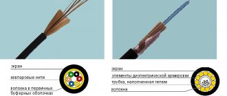
All of these types have different properties related to the ability to transmit an optical signal. For example, the task of SM fiber is to ensure signal transmission with losses not exceeding 0.22 dB/km, and NZDSF fiber is to transmit with minimal dispersion near a wavelength of 1550 nm. But, from the point of view of the suitability of these fibers for welding, these properties do not interest us. The defining characteristic is their design, namely the different configuration of the refractive index profile (RIP) of the core. Without specifying what these differences may be, we will visually compare what the PPP of SM fiber (Fig. 1, left) and NZDSF fiber (Fig. 1, right) looks like.
Rice. 1. SMF PPP diagram (left); NZDSF IFR chart (right)
It is clearly shown that the structure of the cores has a significant difference. It is due to the different distribution of alloying additives. Now let’s imagine that we need to weld these two types of OM with each other. What will happen at the place of their fusion, what will the structure of the core look like? We think no one can answer this question for sure. But this is not necessary - the task is to firmly connect the optical fibers and minimize losses on it. Modern machines cope with this task without any problems, despite the fact that on the screen of a welding machine such dissimilar connections look, to put it mildly, suspicious.
As an example, we present the results of soldering Corning® fibers - SMF-28 Ultra and SMF-28 ULL. And although both of these brands comply with the G.652 standard, they differ significantly in the composition of alloying additives and in the shape of the PPP core. In the first of them, the PPP is close to a step form; in the second, this form is more complex, which ensures record low linear OM losses (less than 0.17 dB/km). The following illustrations demonstrate three combinations of their welded joints.
Rice. 2. Corning® SMF-28 Ultra + Corning® SMF-28 Ultra
Rice. 3. Corning® SMF-28 ULL + Corning® SMF-28 ULL
Rice. 4. Corning® SMF-28 Ultra + Corning® SMF-28 ULL
You can see that the “simple” SMF-28 Ultra welded together best of all, the weld seam is invisible. In the case of the SMF-28 ULL, the seam is clearly visible, and when welding two different types, the seam even emphasizes the difference in the cores.
Let's say right away that this is normal. By subsequently measuring the losses at this junction using OTDR, we can verify that the losses in all cases are within normal limits. You can see the results of these tests by watching our video of the Corning ULL fiber splicing process:
It is also worth noting that Corning® SMF-28 Ultra fiber complies not only with the G.652 standard, but also with G.657. This makes it possible to use this OM both if it is necessary to apply the first standard, and if it is necessary to comply with the second. That is, in those sections of the fiber optic line where the design provides for the connection of two different types of optical fibers, in fact, we connect two identical ones and achieve a minimum of losses. It is this brand of OB that is used as the main one in cables.
Optical fiber splicing equipment
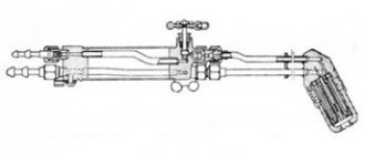
What is the OB welding process? Optical fiber soldering is the process of joining two fibers using high temperature exposure. This effect is produced in welding machines using an arc discharge (voltage arc). The principle of forming this arc is identical in all welding machines and, in general, is not a technically difficult task. The arc temperature can reach 4800°C, while the melting point of quartz glass is 1665°C, which makes it possible to easily melt and join two fibers. The main difficulty in obtaining high-quality OF joints is the task of aligning the spliced fibers. Alignment must be carried out in such a way that the OF cores coincide, since only in this case there will be no interference with the signal. Alignment, or more precisely, adjustment, is the most important characteristic and the main difference between different models of welding machines.
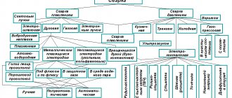
Currently, four types of adjustment systems are relevant:
- adjustment along the Active V-groove;
- adjustment according to PPP (PAS, Profile Alignment System);
- thermal luminescence adjustment (CDS, Core Detection System);
- adjustment by analysis of transmitted light (LID, Light Injection and Detection).
Alignment along the active groove involves analyzing the image of the spliced fibers with a welding machine. After laying in the clamps, the fibers are shifted to the area of the future joint, where their position is recorded by a built-in video camera. The image and position of the clamps are analyzed by a microprocessor, which thus tries to “examine” the fiber cores. When the location of the cores is determined as accurately as possible, the clamp drives move the fibers to the point of their best alignment.
The development of this method was the emergence of PAS - an adjustment system that received a more complex design of the convergence mechanism, a video camera with a controlled variable focal length and very complex algorithms for analyzing the resulting images. All these improvements somewhat improve the accuracy of fiber alignment and significantly increase the cost of the welding machine as a whole. Devices with PAS are also called “mainline”, thus emphasizing their superiority in the quality of results over devices with Active V-groove, which are usually called “urban”.
Devices operating with thermal luminescence adjustment (CDS) are distinguished by the fact that they analyze the image obtained not by transmitted light, but by the radiation of the fiber itself, which is heated by a separate, preliminary arc. This method allows you to obtain even slightly more accurate information about the coordinates of the core. But, in turn, additional heating results in a slight decrease in the strength characteristics of the heating agent.
The last method, LID, is the most accurate and the most complex. It is based on the principle of introducing and recording radiation on a curved fiber. The optical fibers are fixed in special clamps that form their bend. In the immediate vicinity of the first clamp, test radiation is introduced into the fiber, which passes through the fiber and passes into the second fiber, on the bend of which, next to the clamp, a photodetector is installed that captures this radiation. The processor controls the movement of the clamps relative to each other and monitors the moment when the power of the transmitted radiation is maximum. At this moment of truth, the maximum correspondence of the cores is achieved.
It must be said that only devices of the first two types are presented on the Russian market. Devices with CDS and LID are expensive, complex and do not have service support in our country.
In addition to this system, of course, different models of welding machines have many other differences and characteristics. Some may have a touch screen, others boast a compact design, and others have a shock-resistant body. The choice of device model for purchase can be made, of course, based on the price, but one must remember that the difference in price may be due to a significant difference in the configuration or, for example, the conditions of post-warranty service.
Practice shows that currently the quality of welding results for all machines is approximately equal.
To make it easier to choose a particular brand and model, we can provide a comparative table (Table 1), which lists some popular (and not so popular) models and their main characteristics.
Table 1. Comparison of the passport characteristics of various models of apparatus for welding OM.
Comparing two leading Japanese manufacturers and competitors, Sumitomo and Fujikura, you can see that their newest models have approximately the same characteristics. Moreover, having experience working with both equipment, we can confidently say that the capabilities of these models are the same. We confidently recommend them for welding work in the most critical cases.
The choice in this case is usually dictated by personal preferences and the habit of working with devices from a particular company. Some may like that the Sumitomo Type-82 has two independent heaters for shrink sleeves. And some are more attracted by the approach to the design of the Fujikura CT-50 cleaver, which has electric drives that allow you to control the position of the working blade and a built-in Bluetooth module, with which the cleaver can work in conjunction with the device.
These differences are subjective and only affect the ease of use, and only in some cases.
Rice. 5. Sumitomo Type-82C welding machine with FC-6RS-C cleaver.
Rice. 6. Fujikura FSM-86S welding machine with CT-50 cleaver.
For those who want to learn more about the operation of the Fujikura FSM-86S and its differences from previous models, we recommend that you familiarize yourself with our video review:
A review article was also devoted to this model with a detailed description of all the improvements and innovations.
In addition to a welding machine and a cleaver, for successful soldering of optical fibers you must have the following tools and consumables:
- stripper for removing the protective acrylic coating from the OM (Fig. 7);
- lint-free wipes for removing dust and residues of the OM coating (Fig. 8);
- isopropyl alcohol for wiping the OM (Fig. 9);
- KDZS (set of joint protection parts), heat-shrinkable sleeves to protect joints (Fig. 10).
Rice. 7. Stripper for stripping chemical agents from Miller.
Rice. 8. Kimwipes lint-free wipes.
Rice. 9. Isopropyl alcohol.
Rice. 10. Heat-shrinkable sleeves or KDZS.
Watch reviews of welding machines on the VOLS.Expert channel on YouTube
YouTube
How to weld optical fiber: stages of work
It is recommended to do some preparation before starting welding work. Of the mandatory requirements that must be observed during this work, we have identified the following:
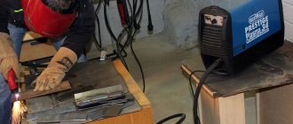
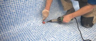
- Preparing the premises. This should be understood as meeting the temperature requirements (from –10°С to +50°С), absence of wind and rain. If work is carried out outdoors, then it is necessary to use a cable technician’s tent or carry out work in a specially equipped vehicle with a passenger body (LIOC). In case of low temperatures, it is recommended to use a heater. It is important not to neglect any of the possible external influences, because in the case of strong wind it will be impossible to work with the OM, if water gets on the welding machine, it may fail, and at low temperatures the device’s battery will discharge almost instantly, and the OM will become extremely fragile.
- Preparation of the workplace. It is strongly recommended that all necessary tools and supplies be laid out within easy reach. It is best to work in a sitting position, and the welding itself will be carried out on the table.
- The use of protective clothing and gloves is mandatory! The hydrophobic gel contained in most cables is a source of severe contamination of clothing and is impossible to wash completely. Also, debris from chemical agents may fall on clothing, and their presence on everyday clothing is unacceptable.
- Preparation of containers or bags for disposal of cable cutting and chemical waste.
- Good lighting should be provided above the workplace. Transparent, cleaned fiber can only be seen in reflected light, and this is necessary both for laying the OM and for collecting debris.
Once everything is ready for work, you can begin. Let's look at the entire workflow in several stages and explain in detail some important points.
Fiber soldering process
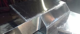
- Optical cable cutting. Usually includes removing the outer sheath of the cable, removing intermediate sheaths, armored covers, reinforcing threads, hydrophobic gel, etc. All aspects of this stage are described in detail in the corresponding article.
- Securing the cable in an optical cross-connect or coupling.
- Removing the shells of optical modules. Attaching modules to the input of the splice cassette.
- Removing hydrophobic gel from fibers. For these purposes, the so-called d-gel, a special liquid, an effective solvent, is used. It is necessary to moisten a rag in it and wipe the fibers until the hydrophobic gel is completely removed. This liquid is commonly called “orange” for its characteristic citrus smell.
- KDZS is put on the fibers of one of the cables being connected. KDZS (or sleeves) consist of two transparent tubes, the outer one made of heat-shrinkable polymer, the inner one made of hot-melt adhesive and a reinforcing metal rod between them.
- Using a stripper, the protective acrylic coating is removed from the optical fiber. The length of the cleared area should be approximately 3-4 cm when using a cleaver with a container for collecting fragments (CT-50). If there is no container, the length should be 5–10 cm. The cleaned area of the OM is wiped with a lint-free cloth soaked in isopropyl alcohol. This is done to remove remaining varnish and possible traces of dust.
- The cleaned OM is placed in a precision cleaver to obtain cleavage. The main task of the cleaver is to obtain a smooth, maximally flat surface of the end of the optical fiber, perpendicular to the axis of the optical fiber. When the end surface deviates from the perpendicular, the quality of welding may deteriorate, so the welding machine monitors the amount of angular deviation and warns if the maximum permissible value (1.5°) is exceeded. Figure 11 shows the procedure for working with the CT-50 cleaver:
A)
b)
V)
Rice. 11. a) laying the prepared OF in the groove, the edge of the protective coating should be at a mark corresponding to the length of the cleaned end of the OF that we want to obtain (12–15 mm is enough); b) closing the lid, at this moment chipping occurs; c) after opening the lid, we can remove the chipped agent.
- Laying chipped fibers in V-shaped grooves and fixing them with clamps. Important! After the OB is removed from the cleaver, the end of the OB should not touch any surfaces - this will inevitably lead to the adhesion of microscopic dust particles on the end of the OB, and this, in turn, will lead to defects in the weld! The ends of the welded OM should be approximately 1 mm from the electrode line, as shown in Fig. 12:
Rice. 12. The fibers are laid in grooves, fixed with magnetic clamps and are ready for welding.
- After closing the windproof cover of the device, the welding cycle starts. The OV is being adjusted. The device automatically determines the type of OB, selecting the optimal arc mode. (If the device fails to cope with the recognition task when working in AUTO mode, you can force the fiber type in the mode settings - SM, DSF, NZDSF, etc., but this is almost irrelevant for modern welders, who almost always correctly identify fibers.) The device produces several preliminary arc discharges, the purpose of which is to burn dust particles and preheat the ends. After which the main, working arc is generated and the OB is simultaneously brought closer together. The process happens very quickly, literally in a second we already see the result on the screen - an image of the welded chemical agents. Also on the screen you can see the estimated value of losses on the resulting connection, which is calculated by the device based on the analysis of this image. It is important to remember that this estimate is an estimate and is not a measurement! Its purpose is to give the installer a reason to doubt the quality of the welding or, conversely, to confirm that everything went well. Typically, cases are considered good when the estimated loss is 0.00-0.02 dB. If you see a loss value of 0.03, it is recommended to digest it.
- The device checks the mechanical strength of the welded joint, stretching the welded fibers with a certain force. If the joint is not destroyed, the device recognizes the welding as successful and emits a sound signal. You can open the windproof cover (Fig. 13):
Fig. 13. Open welding machine cover after welding is completed and the tensile test is successful.
- The welded OM is removed from the clamps, and the KDZS is pushed onto the joint. Important! The KDZS sleeve should be positioned so that the welding site is exactly in the middle. In this position, the OM with the sleeve pulled on is transferred by the operator to the heating chamber. When you close the lid of this chamber, heating begins automatically. When heated, the glue tube melts, and the outer one contracts and forces the glue melt to evenly fill the entire space around the welding site.
- After cooling the seated sleeve, the joint is reliably protected by the hardened glue of the sleeve, reinforced with a reinforcing rod. Important! It is necessary to allow the adhesive melt to cool and completely harden, only after this the sleeve can be placed in the splice cassette. If you try to fix a still hot, uncooled sleeve in the splice cassette cradle, it will become deformed and crush the welded joint when it hardens. This will inevitably lead to losses.
As a visual example of welding work, you can watch a video in which our experts weld 216 fibers:
Comparison of Chinese Jilong welding machines
| Model | KL-300 | KL-300T | KL-280 |
| Functional | |||
| Fiber alignment | Adjustment by core and diameter | ||
| Compensation of surface tension when welding fibers with high eccentricity | Yes, ECF (eccentric core fiber) function is activated automatically in Normal and Special modes | The machine does not have a mode for splicing fibers with a large eccentricity | |
| Splicing fibers with attenuator | The machine does not have a mode for splicing fibers with a specified attenuation | ||
| Types of fibers welded | SMF, MMF, DSF, NZDSF and others. There are 45 fiber types in total. | SMF, MMF, DSF, NZDSF and EDF and others. There are 45 fiber types in total. | 2 types: SMF and MMF |
| Splicing of ultra-flexible fibers: - Corning ClearCurve® G657 - Draka BendBright XS® G657 - OFS EZ-Bend® G657 | There is no separate program for splicing Corning ClearCurve®, Draka BendBright XS®, OFS EZ-Bend® fibers in the menu | ||
| Clamp device | The clamps that hold the fiber in the groove are fixed to the windproof cover and do not separate from it | ||
| The diameter of the coating that can be placed in the carriage | from 100 µm to 1 mm, the same for all devices | ||
| Cleaving lengths for coated fibers 250 µm | from 8 to 16mm | from 8 to 16mm | from 8 to 16mm |
| Cleaving lengths for coated fibers 900 µm (tight buffer) | The minimum chipping length for pigtails is 16mm (there is a limiter) | ||
| Cleaving length for coated fibers 900 µm (loose buffer) | The design of the clamps is normal. The loose-fitting covering is cleaned to its outer edge. The cleaving length is about 30mm | About 16mm, since the KL-300T clamps have a protrusion for grabbing bare fiber at the edge of the carriage (reminiscent of the design of the latest Sumitomo Type-39 clamps) | About 16mm, since the KL-280 clamps have a protrusion for grabbing bare fiber at the edge of the carriage (reminiscent of the design of the latest Sumitomo Type-39 clamps) |
| Clamps for a regular buffer | Yes, all models | ||
| Loose buffer clamps | No | KL-300T clamps resemble Type-39 universal clamps. The device can be used for welding fibers in loose coverings. | KL-280 clamps resemble Type-39 universal clamps. The device can be used for welding fibers in loose coverings. |
| Is it possible to weld 2 fibers together in a free-standing buffer so that they fit in one 60mm protective sleeve? | No | Yes | Yes |
| Is it possible to weld 2 fibers together in a free-standing buffer so that they fit in one 40mm protective sleeve? | No | Yes, but under the sleeve there will be 32mm of bare fiber and only 8mm of buffer (4mm on each side) | Yes, but under the sleeve there will be 32mm of bare fiber and only 8mm of buffer (4mm on each side) |
The image of fiber cores on Jilong devices is very clear. Claims that they do not have core alignment are incorrect. The main difference from Japanese optical welding is not the alignment methods, but the ability to automatically determine the type of fiber. The Japanese machine recognizes the fiber being welded and selects the appropriate welding program for it. In a Chinese device, the operator must manually set the desired program. The KL-300 is closest to Japanese optics welding. Its functional scheme is completely identical to the Japanese one; each microscope is driven by a separate motor. The KL-300T has the same menu and user interface as the KL-300, but its focusing unit is Jilong's original design. Finally, the KL-280 is a restyling of the Kl-260C model and is most different from Japanese optical welding interfaces. This is the most budget model, the simplest, but at the same time not primitive; the KL-280 has everything you need, including universal clamps and a lithium-polymer battery. These things appeared on Japanese welding machines only recently, and even then, not on all of them.
| Design features | |||
| Number of axes along which fibers are aligned and observed | Along 2 axes, X and Y | Along 2 axes, X and Y | Along 2 axes, X and Y |
| Image Processing/Alignment System | P.A.S. | P.A.S. | P.A.S. |
| Enlargement of the fiber image on the splice screen. Note: This ALWAYS refers to digital magnification, the actual optical magnification of microscopes on all welding machines is approximately x10 to x20 | 300x or 150x depending on viewing mode (switched by X/Y button) | 256x or 128x depending on the viewing mode (switched by the X/Y button) | 344x when viewing a fiber image in the X field or in the Y field. And 168x when simultaneously displaying images from cameras X and Y (Function key). |
| Monitor | LCD with screen diagonal 5.6 inches | LCD with screen diagonal 5.6 inches | LCD with a screen diagonal of about 5 inches |
| Availability of touch screen | No | No | No |
| Possibility to adjust the monitor rotation angle | Yes | Yes | Yes |
| Rotate the image 180° when the monitor is installed in the uppermost position | Yes, activated through the menu for all models | ||
| Availability of additional protection on the mirrors of the optical system | No, because the reflective layer is applied on the back side of the mirror | ||
| V-groove illumination | Yes, built-in white LED | ||
| Displaying images on a monitor or TV | to monitor via VGA | to monitor via VGA | No |
| Interface for communication with a computer | USB 1.1 | USB 1.1 | RS232 port |
Jilong's optical design is classic, with mirrors on a windproof cover. The mirrors have a round shape, and not rectangular, like the Japanese. A reflective layer was applied to the back of the mirror from the very beginning, which ensured greater durability of the mirrors. Electrodes for all models are unified. Some nodes are also unified. For example, the KL-300T universal clamps can be installed on the KL-300, the same goes for batteries and heat shrink ovens. All this makes Jilong the most repairable device in Russia, and its spare parts and accessories, all other things being equal, cost almost 2 times less compared to their Japanese counterparts.
| Features of internal software | |||
| User Interface | The text menu and cursor are very similar to the Fujikura FSM-40S/50S menu, but not identical to it | Text menu and cursor, similar to KL-260 | |
| Keyboard | Buttons with English text and symbols | Buttons with English text and symbols | Buttons with English text |
| Self-test mode | No, just check for dust | No, just check for dust | No |
| Training video | There is no training video or photo in the internal memory | ||
| Program for downloading data to PC | For all models, these programs exist only for Chinese Windows and exclusively in Chinese | ||
| Calendar | Yes | Yes | Yes |
The menu of the KL-300 and KL-300T is indeed very similar to the FSM-40S, the general structure, names of parameters and programs, some numerical values are the same. However, there is no complete similarity. For example, focusing is only possible automatically. The KL-280 menu has nothing in common with the Japanese one; it is identical to the KL-260C.
| physical characteristics | |||
| Weight | 2.7kg without battery, 3.2kg with battery | 2.7kg without battery, 3.2kg with battery | 3.5 kg with battery |
| Dimensions (excluding protruding parts) | 150L x 150W x 150H (mm) | 150L x 150W x 150H (mm) | 150L x 150W x 160H (mm) |
| Volume | 3.4 liters | 3.4 liters | 3.6 liters |
| Transport case included | A hard case unified for all models, reminiscent of the FSM-50, only smaller in size and with a different internal layout. | ||
All Jilong optics welds are approximately the same size and weight. In terms of compactness, they are inferior to the FSM-60, but the set of the Chinese device, packed in a case, takes up almost 2 times less volume than the full set of the Japanese one, mainly due to the accessories. A compact battery is constantly located inside the device, a small power supply, etc. The case can be worn on a belt over your shoulder or by the handle; it does not interfere at all when walking. Only the Fitel S-177 has such ergonomics.
| Conditions of nutrition, operation and storage | |||
| terms of Use | -10 to +50°C at <95% relative humidity without condensation | ||
| Storage conditions | -40 to +60°C at <95% relative humidity without condensation | ||
| AC power supply | from 100 to 240V 50/60Hz | ||
| DC power supply | nominal 13.5V | ||
| At what altitude above sea level is operation permissible? | Up to 5000m | ||
| Maximum permissible wind speed during operation | 15 m/s | ||
| Replaceable battery | Lithium polymer battery KL-2-26L7; 10.8V; 8000 mAh | ||
| Charging the battery during operation | Yes, all models | ||
| Number of welds from one full battery charge | The number of welds is approximately 2 times greater than the number of complete cycles (welding + heat shrinking) | ||
| Number of heat shrink welds from one full battery charge | 150 claimed | 150 claimed | 130 declared |
The lithium polymer battery is a definite advantage of Jilong. The battery charges while operating from the mains, retains its charge for a long time during storage, and with a capacity of 8 Ah it is unusually compact. It can be moved from one device model to another, and there is no need to “train” it to maintain its capacity. The price is approximately 2 times less than Japanese analogues, all other things being equal. It remains to add that the KL model range works from the mains, both with and without a battery inserted inside. And if you pull out the power cord from a working Jilong with a battery inside, the welding will continue to work as if nothing had happened. Fujikura turns off while charging the battery from the mains if you remove the power cord.
| Features of the welding process | |||
| Checking the chip angle before welding | Yes, the limit value is set from 0 to 10°. Default is 3°. Angle values are displayed. | Yes, the limit value is set from 0.5 to 8°. Default is 3°. Angle values are not displayed. | |
| Check for dust and cracks before welding | Yes, but there is no separate message for dirty chips of bad shape in the new versions, but there is a single message “Bad chip”. | ||
| Automatic selection of welding program (Auto mode) | The Auto SM, Auto MM, Auto DS and Auto NZ KL-300 programs operate similarly to the SM Auto and MM Auto programs in the Fujikura FSM-60. They calibrate the arc, but do not determine the types of fibers. | The SM and MM KL-280 programs operate similarly to the SM Fast and MM Fast programs in the Fujikura FSM-60. They do not specify fiber types. | |
| Automatic splicing of non-matching fiber types | There are 27 special programs for splicing mismatched fiber types (Special mode), but they are not automatically activated. | There are no special programs for splicing fibers of mismatched types. | |
| Availability of manual welding mode | Yes, in Normal and Special modes. To do this, you need to set the Mixing Settings to “Manual” and turn off “Re-Mixing” | On later versions, in Manual mode you can move the motors, but you cannot cook fibers | |
| Duration of welding from start to loss assessment | about 15 seconds, depends on the selected welding mode | ||
| Number of welding programs | 40 in total: 12 factory installed and 28 custom. In this case, you can set 18 matching and 27 mismatching fiber types and 4 welding modes: Auto, Calibrate, Normal and Special | A total of 40 programs: 12 preset at the factory and 28 user-defined. In each of the user-defined programs, a choice of 53 welding modes is possible. | SM programs: 6 preinstalled at the factory and 94 for user installation. MM programs: 6 pre-installed at the factory and 94 for user installation |
| Programmable changes: - arc power during welding - fiber stretching during welding (for special types) | Yes, similar to how it is done in FSM-40 and FSM-50 | No | |
| Automatic optimization of arc power before each welding | Yes, in Auto and Calibrate modes | No | |
| Automatic compensation: -deformation of electrodes (due to carbon deposits); -differences in the melting of fibers that do not match in melting temperature; - mismatch between the positions of the arc and electrodes; - environmental influences on the arc (temperature, humidity, altitude) | Yes, via Arc Test (Discharge Calibration) | Yes, using the arc test (Test button), in addition, there are 2 types of electrode firing. | |
| Availability of atmospheric pressure, temperature and humidity sensors | There is a sensor for heating the stove, temperature inside and outside the device, pressure, plus the voltage is shown. | No | |
The information that Chinese welding machines weld fibers melted during arctest is fiction. Not a single Chinese machine will weld melted fibers, even forcibly. On early versions of the KL-280, the device even informed the user about large dust, requiring the fiber to be cleaned. When welding cable fibers, traces of grease can rarely be completely avoided, so the criteria for testing for dust were subsequently somewhat relaxed by the developers, but the shape and angle of the chip were always strictly observed.
| Post-weld processes | |||
| Insertion loss when splicing identical fibers, measured using the “break and remake” method | 0.02dB SMF, 0.01dB MMF, 0.04dB DSF, 0.04dB NZDSF | ||
| Criteria by which losses in a welded joint are assessed | Three evaluation modes: Core, Shell and Precise. Used: diameter of mode fields of left and right fibers, axial displacement and angular deformation of cores (very similar to FSM-50). | No data | |
| Error in estimating losses in a welded joint | Not standardized | ||
| Return losses in a welded joint | Claimed: better than -60 dB | ||
| Tensile Testing of Spliced Fibers | Tension equivalent to 200 grams | ||
| Memory capacity for welding results | 4000 results; Number, fiber type, date, loss. | 5000 results, splice number, date and losses are indicated | |
| Saving images of fibers before and after welding for later viewing | No | ||
| Is it possible to turn on an additional arc after welding the fibers? | Yes, with the Arc button. You can adjust the duration of the additional arc from 100 to 30000ms | Yes, with RUN button | |
The reliability of estimating losses in a welded joint has always been a sore subject for all types of apparatus. We can only state (once again) that exact losses can only be measured with a reflectometer. In addition, the installer can check the quality of the weld joint visually, using the image of the weld on the screen. All models provide the opportunity to view each field after welding separately, in good magnification and quality. Axial displacements of the fibers (if any) will be clearly visible.
| Weld joint protection | |||
| Shrink Oven | Built-in single oven, with a surface covered with a non-stick mat. | ||
| Does the oven turn on automatically when fibers are placed in it (autostart)? | No | ||
| Maximum thermowell length | maximum 60mm | ||
| Number of shrink programs | 24 in total, 9 of which are preinstalled at the factory. | Universal program with adjustable shrinkage time | |
| Programs for shrinking KDZS “open type” (Japan) | Yes, FP-03 programs are available; FP-03 Ny-08; FPS-01, optimized for shrinkage of Fujikura and Sumitomo KDZS of all lengths 60mm, 40mm and 20mm. Japanese sleeves fit well. | see above | |
| Programs for heat shrinkage of semi-shrinkable "European type" KDZS | No | No | see above |
| Heat shrink time 40mm KDZS | Depends on the selected mode, KDZS type and feeding method, by default more than a minute. The user is recommended to set the optimal time himself | Depends on the type of KDZS, set by the user. Default is 35 seconds. | |
| Heat shrink time 60mm KDZS | Depends on the selected shrinkage mode, type of KDZS and feeding method, default 55 seconds | Depends on the type of KDZS, set by the user. Default is 35 seconds. | |
| 50g preload created by the furnace clamps to keep the fiber taut (straight) | No | No | No |
The design of the heat shrink oven for all Jilong devices is classic and therefore reliable. Heating element and Teflon pad. In case of mechanical damage to the stove body (for example, from an impact), you can replace both the stove body and its entirety. For Sumitomo Type-39, this will require replacing the entire top of the device. The non-stick mat extends the life of the Teflon coating. The stove is a standardized spare part for Chinese devices; it is inexpensive (for comparison, the Sumitomo Type-37SE stove costs about 900 USD). If necessary, it can be easily changed, while owners of Japanese devices have to be content with repairing an old stove.
On our website you will find components and equipment for the construction and maintenance of fiber optic lines at the lowest prices.
The Fibertool service center, which has a network of representative offices throughout Russia and the CIS, provides service for welding machines during the warranty period of 1 year, and also offers:
- long warranty of 3 years from the date of purchase of the welding machine;
- maintenance of any fiber optic welding machines and fiber-optic communication equipment;
- metrological verification of equipment;
- rental of fiber optic splicing machines;
- Optical fiber welding training.
Common mistakes when welding OM
After studying the instructions for the welding machine and reading this article, you can safely begin welding work. Will it work? If you have a head on your shoulders, your hands grow from the right place and the instructions are followed... Why not, of course it will work out! But this statement is true to the extent that the opposite is also true - it will not do without mistakes. Moreover, let us tell you an annoying fact - they will happen regularly and for some time. Some installers make some mistakes without even realizing they are mistakes.
The thing is that it is perhaps impossible to foresee and prevent all possible undesirable situations when working with optical fiber - because each installer can make new mistakes, as no one has done before.
Let's look at several common mistakes and comment on them.
- Some installers stubbornly refuse to hold the stripper correctly while removing the acrylic coating. We look at Fig. 14, Fig. 15 and Fig. 16:
Fig. 14. The stripper should not be held at a strong angle to the stripping direction - the fiber experiences local bends and may receive microdamage.
Fig. 15. It's even worse!
Fig. 16. But this is correct.
- If you handle the chopped fiber carelessly and proceed as shown in Fig. 17, then when placed in the apparatus we will see a picture like in Fig. 18. And the welding result will be as in Fig. 19:
Fig. 17. Accidentally poked chipped fiber into clothes... Or was it not by accident?
Fig. 18. Accident or not, it doesn’t matter anymore. It is important that dirt sticks to such fiber.
Fig. 19. If welding is done, the result is guaranteed to be disappointing. And don’t let the 0.01 dB “estimate” reassure you. This is a marriage!
- Sometimes on the screen you can see a picture like the one in Fig. 20. Cleaving angle 3.7°! The device signals indignantly, highlighting this circumstance in red. Actually, there is no error here; such a situation can happen sooner or later - as a rule, this means that the cleaver blade has become dull. A mistake would be the decision to ignore the warning about a bad chip and still carry out welding. We didn't.
Fig.20. The angle of the chip is no good. If you weld with such a chip, expect losses.
- A serious mistake is that the shrink sleeve does not cover the edge of the buffer coating (the same is true for acrylic coating). The strength of the fiber near the joint decreases. See Figure 21:
Fig.21. The sleeve moved to the side while being placed in the heater. You can not do it this way!
- And a very amateurish option - the sleeve, which had not had time to cool, was installed in a splice cassette. See Figure 22. It doesn't cost anything to crush hot shrink. And along with it, the fiber inside!
Fig.22. Flattened.
How to avoid this and any other disgrace in your future work? The answer is simple - only practical work experience will give you confidence and teach you to be careful.
And you can take the first steps in this direction quite successfully in editing classes at Educational. In the presence of teachers, you will be able to immediately notice your mistakes, and most importantly, learn not to make them!
More about training
Features of the iLsintech SWIFT-S3 welding machine
- A powerful rechargeable battery powers the SWIFT-S3 for 250 welding/shrink cycles.
- A 4.3-inch two-position color display with a control panel and an intuitive menu makes working with the welding machine as comfortable as possible.
- The built-in oven allows for heat shrinking of two KDZS simultaneously, which increases the installation speed by 20%.
- Dust- and moisture-proof design will ensure high-quality installation in windy weather or rain.
- Small dimensions (138*160*135) and weight (2.3 kg), as well as an impact-resistant housing, allow the iLsintech SWIFT-S3 to be operated on the operator’s belt.
- Possibility of installing connectors