A distinctive feature of electronic technologies is the increasingly compact installation of radio components and microcircuits, which has led to the emergence of BGA-type packages. When soldering them, several contact legs and pads located under the bottom of a digital controller or a small chip are processed at once.
Such microminiaturization often results in certain inconveniences caused by the difficulty of repairing (soldering) elements located in the BGA package. When handling them, you should act very carefully, following certain precautions and recommendations. Thus, BGA soldering involves a well-thought-out technique for processing the contacts of microcircuits of a known class.
Introduction
The development of microelectronic components is constantly moving towards increasing integration, performance and functionality.
This process is characterized by an increase in the density of active elements on the chip by approximately 75% per year, and this, in turn, necessitates an increase in the number of their pins on the package by 40% per year. This is due, firstly, to the constantly growing demand for new packaging methods, and secondly, to an increase in the density of interconnections on the printed circuit board. As a result of general trends, the area of mounting substrates is decreasing by approximately 7%, and the physical dimensions of electronic equipment by 10–20% per year. This trend is supported by the continuous increase in interconnect density due to the reduction of printed circuit elements. All this seriously affects the electronics production system: the cost of fixed assets increases, the volume of direct costs increases, and the production cycle increases. As a result, all this leads to an increase in the cost of electronic products, unless special measures are taken to reduce their cost.
Soldering iron
PS-900 METCAL – induction soldering system. A soldering iron power of 60 W is quite enough to work with multilayer boards of modern electronics. Phone repair engineers have 4 years of experience working with this particular soldering iron. What are the distinctive features of the PS-900:
- no need for calibration,
- large selection of tips,
- reliability of the station, the consumable material is the inductor. With daily intensive soldering, the inductor is replaced on average once every 10 months.
Soldering iron
IC package designs
From the very beginning, chip dies were placed inside ceramic or plastic cases. Until about 1980, all microcircuit packages had leads designed to be placed and secured in metallized holes (PTH, Plated Through-hole - metallized hole) of the mounting substrate and subsequent mounting soldering. At the same time, the most acceptable pitch of mounting holes on printed circuit boards was formed: in the USA - 2.54 mm (1/10 inch), in our country it was rounded to 2.5 mm, which at some point in history gave rise to conflicts in standardization systems .
Later, with increasing integration, outputs began to be made in a form suitable for surface mounting technology (SMT - Surface Mounting Technology), which has become the predominant technology for mounting electronic components today. Passive or low pin surface mount components essentially increase packaging density by simply reducing the size. Modern resistors and capacitors are formed into chips the size of a poppy seed or even smaller. Increasing the density of a microcircuit layout cannot follow such a simple path: geometric space is required to accommodate numerous pins on the component body and the mounting field of the board.
The main ways of placing the pins of microcircuit packages are:
- peripheral arrangement of pins, when they are located at the edges (on the periphery) of the crystal or chip body;
- matrix arrangement of pins on the flat surface of the housing.
Most types of microcircuits have peripheral pinouts. The pitch of peripheral pins is limited to 0.3 mm (practically 0.4 mm), which allows up to 500 pins to be placed on microcircuits with large packages. But you need to take into account that when the lead pitch is less than 0.5 mm, the complexity of installation and the amount of repairs increase. The configuration of peripheral leads can take various forms: “gull wing”, J-shaped (with soldering under the body), I-shaped (for butt soldering), leadless with soldering at the end of the body [2].
Components with matrix pinouts offer even greater variety:
- CSP (Chip-scale Packages - a package commensurate with the size of the crystal);
- PBGA (Plastic Ball Grid Array - plastic cases with ball matrix leads);
- CBGA (Ceramic Ball Grid Array - ceramic packages with ball matrix outputs);
- PPGA (Plastic Pin Grid Array - plastic cases with matrix contact pads);
- CCGA (Ceramic Column Grid Array - ceramic packages with columnar matrix outputs).
It is assumed that microcircuits with a number of pins from 150 to 200 will be manufactured in packages with peripheral pins. For microcircuits with more than 150–200 pins, a matrix pin system is preferable, since it makes it possible to place a large number of pins in a limited area.
The pin designs in the matrix system have less variety:
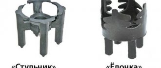
- pillar leads made of solder, reinforced with a “tangle” of thin wire, for microcircuit packages and multi-chip MCM modules (Multi-Chip Module), often called a pad grid, a land grid;
- ball grid array (BGA - Ball Grid Array) with pin pitch 1.50 mm (0.060 inch), 1.27 mm (0.050 inch), 1 mm (0.040 inch), 0.8 mm (0.03 inch) and less .
The matrix output system provides a number of obvious advantages. The most important are:
- minimum area of the mounting field of the substrate;
- availability of free spaces for placing heat sink elements on the substrate;
- better conditions for ensuring the functional performance of electronic modules due to lower parasitic effects on high-speed operations;
- simplification of surface mounting technology on a printed circuit board through the use of solder reflow processes during group heating;
- greater yield of finished products. (Although there are concerns that quality may be lost due to the inability to directly visually inspect connections.)
But still, mounting components with matrix pins involves additional capital investment to ensure the positioning of pins on the board and testing solders that are not accessible for visualization. The limited length of the leads does not provide damping to compensate for the mismatch in thermal expansion of materials in the hierarchy of interconnects (Fig. 1) and does not provide the resistance to mechanical stress associated with deformation of the substrates necessary for special conditions. Because of this, the list of materials for use in this interconnect system is very limited. And they are all more expensive than usual. The trend toward ever smaller lead pitches (< 1.0 mm) further exacerbates this problem.
Rice. 1. Mismatch of thermal expansion of materials in the hierarchy of interconnections of BGA components on the mounting substrate
In this regard, practical testing of other combinations of materials is underway: damping polyimide films (Tape BGA - TBGA), ceramic substrates (CBGA - Ceramic BGA or PGA - Pin Grid Array). It is obvious that the use of a ceramic substrate allows one to obtain excellent results: resistance to thermal cycles of CBGA packages not mounted on the board [3]. That is, the problems of combining CBGA pins with a glass epoxy base are solved during the installation process.
BGA components
BGA technology originated approximately 20 years ago at IBM for internal consumption. The first company to learn from IBM was Motorola, which bought a license from IBM and developed its technology into a package called OMPAC (Overmoulded Plastic Array Carrier). The structure of the BGA component is shown in Fig. 2.
Rice. 2. BGA component in a plastic case
According to this scheme, the crystal is mounted on a mounting substrate made of a composite material with an organic binder (FR-4, FR-5, BT) having a high glass transition temperature. For these purposes, it is preferable to use a material based on BT (Bismaleimid Triasine) with a particularly high glass transition temperature and excellent electrical properties. A NiAu finishing coating is applied to both sides of the substrate, which is universal for microwelding (welding wires from the microcircuit to the substrate) and soldering ball leads.
The crystal is glued to the substrate with a thermally conductive epoxy resin adhesive. In turn, the substrate has elements of conductive heat removal from one side to the other. Some of the ball leads are intended for thermal connections.
Modern standards set the pitch of the grid of matrix leads: 1.5 mm, 1.27 mm and 1.0 mm and the diameter of the ball leads is 0.6 mm. The designs of 50x50 mm substrates allow 2401 pins to be placed on them with a pitch of 1.0 mm.
Chip chips are mounted on a substrate using one of four methods:
- Thermocompression microwelding (wirebonding) is the oldest, most flexible and widely used method (Fig. 2). More than 96% of all microcircuits are still manufactured with its help.
- Attaching crystals to tape media terminals (Fig. 3), or TAB (Tape-automated Bonding). This method is used for automatic mounting of crystals with a small lead pitch onto an intermediate carrier. In addition to the possibility of automating installation, it provides the possibility of preliminary testing of crystals before final installation on the mounting substrate.
- Attaching an inverted crystal (Flip Chip) through ball terminals (Fig. 4). The compactness and improved electrical performance of this interconnection method are helping to expand its application.
Rice. 4. Installation of the microcircuit on the substrate using the inverted crystal method (Flip Chip)
- Connecting the crystal with beam leads (Fig. 5). This method uses technologies for thermocompression and ultrasonic microwelding of beam leads to peripheral contact pads on the chip and then beam leads to the substrate.
Security Methods
Ventilation: Flux fumes from soldering and desoldering can be harmful. Use general or local exhaust hoods to comply with the Maximum Permissible Concentration of Harmful Substances in the workplace. Consult the technical data sheet (MSDS) for soldering materials for permissible maximum concentration limits.
Personal Protection: Chemicals used in the reballing process may cause damage to areas of the skin. Use appropriate safety equipment when performing cleaning, soldering or desoldering activities
Lead Hazards: The USEPA Carcinogen Assessment Group classifies lead and its alloys as teratogens and its components as a Class B-2 carcinogen.
When working with static-sensitive components, ensure that your work area is static-free by using the following:
- Fingertips
- Conductive work mat or table cover
- Grounded heel or wrist bracelets
Microenclosures
Further development of the layout of microcircuits led to the possibility of their placement in a package commensurate with the size of the crystal - in microcases. In English terminology, they are called Chip Scale Package - CSP, and Chip Size Package - CSP, as well as μBGA and, finally, Slightly Larger than an IC Carier - SLICC (“slightly larger than the chip chip”). In Fig. 6 you can see that this is indeed the case. The size of the ?BGA micropackage, as a rule, does not exceed 20% relative to the crystal size.
Rice. 6. μBGA (CSP) micro package layout
A type of arrangement called μBGA (Fig. 6) is a micro-package in which the chip chip is placed. To dampen the crystal, some neutral, heat-resistant elastomer (for example, silicone) is applied to it. It houses a polyimide carrier for TAB-type interconnects. The carrier shanks are welded to the peripheral terminals of the microcircuit crystal. A matrix of contact pads coated with NiAu is placed on the carrier field. In this form, the microcircuits are tested and then delivered to the consumer. Upon request, ball leads are soldered onto the contact pads. Modern achievements provide a ball diameter of 85 microns, a pitch of leads in the matrix - 1.27 mm, 1.0 mm, 0.8 mm, 0.65 mm, 0.5 mm. The microbody size is only 0.3 mm larger than the die size.
The SLICC housing uses a glass epoxy base as a mounting substrate (Fig. 7). The connection between the crystal and the substrate is carried out through lead balls placed directly on the surface of the microcircuit crystal. Modern printers make it possible to accurately position and normalize doses of solder paste onto semiconductor wafers (“wafers”), on which solder balls form after reflow. They are used to mount the crystal on a glass epoxy substrate. Essentially, the mounting substrate in SLICC packages serves to increase the pin pitch from the chip to the board. This design solution does not compensate for different coefficients of thermal expansion. Instead, the heterogeneous system is held together by pouring a compound into the space between the crystal and the substrate.
Rice. 7. SLICC housing
Moisture Susceptibility Level Chart
| Susceptibility level | Exposure time (outside the protective bag) at 30 degrees C/60% relative humidity or as expected |
| 1 | Unlimited when |
| 2 | 1 year |
| 2a | 4 weeks |
| 3 | 168 hours/td> |
| 4 | 72 hours/td> |
| 5 | 48 hours/td> |
| 5a | 24 hours/td> |
| 6 | Forced drying before installation. After drying, it must be installed within the time indicated on it. |
Direct mounting of crystals on the board
The need to reduce the weight and dimensions of electronic equipment structures has led to interest in methods of directly mounting microcircuit chips on a board (DCA - Direct Chip Attach): these are “chip-on-board” (Chip-on-Board) or multi-chip modules (MCM - Multi- Chip-Module).
When assessing the possibility of using these methods, it is necessary to again take into account the different temperature expansion coefficients of the silicon crystals and the mounting substrate. In addition to a direct solution to this problem - choosing the appropriate substrate material, another way is used: filling the cavity separating the crystal and the board with epoxy resin (Fig. 8). This technique makes it possible to equalize the deformations of the crystal and the substrate and thereby significantly improve the reliability of such assemblies.
Rice. 8. Sequence of operations when installing a crystal on a board
When directly installing crystals on mounting substrates, it is not always possible to first verify their correct operation before mounting them on the substrate. To date, several technologies exist to solve this problem. In foreign terminology, it has the name “known good crystal” (KGD - Known Good Die). One way to solve this is to use micro-packages, the dimensions of which are only slightly larger than the dimensions of the crystal. But this allows you to perform the function of protection from the external environment and redistribute the pins of the crystal to the pin matrix of the microcase. In turn, the use of micro-cases makes it possible to test the microcircuit before installing it on the mounting substrate. On microcircuits with programmable logic (FPGA), it is possible to program them by burning jumpers in accordance with the intended circuit. A typical example of micro-cases is a CSP-case (CSP - Chip-Scale Packaging).
Because some CSP packages have pin pitches of 0.5 mm (0.020 in) or less, special PCB manufacturing techniques are required to accommodate signal routing in the narrow spaces between board elements.
Multi-chip modules (MCM)
Multi-chip modules belonged, until the early 1990s, to the areas of space and military technology and the high-end computer industry. IBM was the first to succeed in the practical use of MSM when organizing the production of a series of fourth-generation computers. Multilayer ceramic boards were used as a mounting and heat-dissipating base. A plant for their production was built especially for this purpose. A large amount of work is currently being carried out in Germany, in particular, at the University of Rostock and the Technical University in Berlin, where, through the use of MSM technologies, the layout is increased not only in the plane of the module, but also along its vertical (Fig. 9).
Rice. 9. Experimental samples of MSM elements at the Technical University of Berlin
In the 1990s, the use of MSM was the only solution to increase integration and correspondingly increase the functionality of the equipment. At that time, investments in the creation of multi-chip modules were less than investments in microelectronics.
But later, the development of electronics followed the now traditional path - along the path of increasing the integration of microcircuits, which entailed huge investments in their production. These trends can still be seen today. Chip factories built in Southeast Asia with topological resolutions of 0.065 microns and 0.093 microns are not yet fully loaded. Therefore, today efforts are focused on projects that would take advantage of the capabilities of developing microelectronic production.
However, MSM projects are being seriously developed where other ways of integration are not available for one reason or another.
The main difficulty in creating MSM is the difficulty in testing microcircuit crystals. If the probability of getting into the three-chip module is 95% of suitable microcircuits, the yield of suitable MSM is 85.7%. Next comes the question of identifying good and bad module components. The profitability of MSM production is directly related to the probability of suitable microcircuits.
Rice. 10
Rice. eleven
Rice. 12
Anyway, the most expensive part of MCM is the base (substrate). Table 1 shows the design options for MSM mounting bases. The MCM-L option is preferable from a cost-effective perspective.
Table 1. Modern ideas about multi-chip modules
Printed circuit boards
Existing technologies for the production of printed circuit boards are capable of mounting the pins of unpackaged microcircuits if it is performed using thermocompression welding technology or using tape media (TAB technology). With this solution, difficulties in protecting exposed chips arise when packaging electronic modules, but this solution still remains one of the most effective methods for mounting bare chips.
When using packages with a small pitch of matrix pins, the situation is complicated by the fact that signal connections from the internal pins of the matrix must be routed between the contact pads of the matrix. In this case, it is possible to conduct one, or maximum two, conductors between the contact pads. Therefore, in most cases, conductors from the internal pins of the matrix are routed through the internal layers of multilayer printed circuit boards.
Traditional technologies of multilayer printed circuit boards using through-hole metallization do not allow mounting of microcircuits with matrix pins with a pitch of less than 1.0 mm (0.040 inches). But CSP-type microcircuit packages with matrix pin pitches of 0.508 mm (0.020 inches) and 0.254 mm (0.010 inches) have already been created. To install such components, special layers with blind metallized holes are added to the MPP, on which circuits are routed from under micro-cases or from under unpackaged microcircuit crystals.
Such thin additional specialized layers are pressed onto the MPP, after which blind metallized holes are made in them. Therefore, this method abroad was called (literally) “surface laminar circuit”, or SLC (Surface Laminar Circuit). And although in Russia there is not yet an established term for this method, it can be seen that it combines the method of metallization of through holes and the method of layer-by-layer building. This means that it can be given a long name - “MPP with layer-by-layer build-up of outer layers” or “MPP with blind holes” until a more laconic name is established among Russian specialists.
Cleaning the Retainer
| During the BGA reballing process, the fixative becomes increasingly sticky and dirty. Rice. 10 shows traces of contamination on the fastener. It is necessary to clean the remaining flux from the clamp so that the stencil fits correctly. The process described below applies to both flexible and rigid fasteners. For better cleaning, it’s a good idea to use an ultrasonic cleaning bath Tools and materials
Additional recommended tool
|
| Step 1 - Soak Soak the BGA stencil fixative in warm deionized water for approximately 15 minutes. |
| Step 2 - Cleaning with Deionized Water Remove the retainer from the water and scrub it with a brush. |
| Step 3 - Rinse the Retainer Rinse the retainer with deionized water. Let it air dry. |
Number of pins and degree of integration of microcircuits
When mounting crystals on a housing substrate and a housing on a mounting substrate (board), or when directly mounting a crystal on a board, the area used for this inevitably increases. This is caused by the need to allocate a certain physical space to accommodate the pins. And the number of pins follows the general trend of their increase with increasing integration of microcircuits:
where n is the number of pins, q is the coefficient of connectivity of microelements in the structure of the microcircuit, N is the degree of integration of the microcircuit, R is the Renta index [4].
In contrast to the degree of integration, this effect is called the degree of disintegration, which is estimated by the ratio of the density of microelements per mounting area on the board with their density on the chip. For example, if the processor chip has a size of 10x10 mm, and the mounting field of its case on the board occupies an area of 4000 mm, this design of the interconnection system is characterized by disintegration with the number 40. What value is estimated for a matrix of 800 pins? The peripheral location of such a number of pins with a pitch of 0.4 mm occupies an installation field with an area of 8000 mm, which means that the degree of disintegration of such a design is 100.
It should be noted that the degree of disintegration increases as the hierarchical level of the design increases: crystal - microcircuit - printed circuit assembly - module - block... For example, disintegration in a block can reach 100 thousand.
Table 2 shows data on a rough assessment of disintegration when using various methods of packaging and installing processor chips on a mounting base (board).
Table 2. Estimation of disintegration when moving to the next level of interconnections
It is obvious that the degrees of integration and disintegration must correspond to the technical level of production development. If you try to complete the design at the maximum production capabilities, the cost of the product will become unreasonably high due to the large amount of scrap waste. The reliability of such structures will also not be guaranteed. If a product is put into production, designed according to low design standards, that is, with a high degree of disintegration (microcircuit of large dimensions), its high material consumption, low capital productivity (“from a gun to sparrows”) will also have a detrimental effect on its cost.