02/01/2022 Author: VT-METALL
From this material you will learn
:
- Requirements for weld parameters
- Methods for calculating the length of the weld and other connection parameters
- Calculation of the length of the weld based on the mass of the metal
- Calculation of weld leg length
The length of the weld is one of the parameters that affects the strength of the entire joint. When calculating a joint, it is necessary to take into account many factors: the type of metal, the mass of the parts being welded, stress, etc. Only after this can the length and other characteristics be determined.
Depending on the type of parts and the method of their connection, approaches to calculating the length will vary. In our article we will tell you how to calculate this parameter, what affects the calculations and what requirements are imposed in regulations.
Requirements for weld parameters
In order for all parts to be connected to each other in accordance with the standard and according to a certain technology, it is necessary to constructively design the welding joint itself.
It should be remembered that the smaller the volume of welding in the structure itself, the smaller the welding deformations when using seams of the smallest thickness. These indicators can be determined through calculations or design considerations.
To perform the work better, do not allow the seams to be close to each other and the seams to form closed contours. In addition, it is worth avoiding the transverse orientation of the seams in the rod, which creates tensile stress in cases where the ends of the rod are fixed to avoid displacement during welding.
VT-metall offers services:
Welded joints of beams are made end-to-end, without overlays. Two welding options are possible:
- Double-sided with full penetration.
- Single-sided with root welding or on spacers.
In this case, the ends are brought out onto technological strips, cut and cleaned.
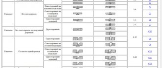
The table shows the purpose of the fillet weld leg
:
The fillet weld leg should not be higher than 1.2t, where t is the thickness of the thinnest element of the connection.
The estimated length of the fillet weld should not be less than 4kf (4 legs of the weld) and not less than 40 mm.
The overlap should not be less than 5 times the thickness of the thinnest element being welded.
The largest value of flank welds should not exceed 85βfkf, because the actual stress along the length of the weld will be uneven and some areas along the edges may experience overstress, and areas in the middle, on the contrary, will be understressed in comparison with the calculated value. This does not apply to those types of seams in which the force occurs throughout the entire length, for example, in the waist seams of beams.
Welding metal that is too thick and too thin is not recommended, as tension may cause the thin metal to bend.
Content
- 1 area of use
- 2 Normative references
- 3 Terms and definitions
- 4 General tolerances
4.1 Tolerances of linear dimensions
- 4.2 Tolerances of angular dimensions
- 4.3 Tolerances for straightness, flatness and parallelism
- 6.1 General provisions
Appendix YES (informative) Information on compliance with reference international standards
national standards
NATIONAL STANDARD OF THE RUSSIAN FEDERATION
Welding
GENERAL TOLERANCES FOR WELDED STRUCTURES
Linear and angular dimensions.
Shape and location
Welding. General tolerances for welded constructions. Dimensions for lengths and angles. Shape and position
Date of introduction: 2017—10—01
Methods for calculating the length of the weld and other connection parameters
When calculating the length of the weld, it is first necessary to eliminate or minimize the parameter errors that affect the strength of the joint. First of all, it is an indicator of compression and tension of the metal. To determine this process you need a formula:
Where:
Yс
– coefficient showing workplace conditions. This indicator is considered generally accepted and can be found in the corresponding tables. It is necessary to substitute the desired indicator into the formula.
Rу
– metal resistance index, which takes into account its fluidity. It can be found in specialized reference books.
Ru
– the second indicator of metal resistance. It can be found in reference books.
N
– indicator of the maximum permissible load on the joint.
T
– the value of the thinnest wall thickness of the parts being welded.
Lw
— maximum length of the weld. When calculating, this parameter must be reduced by 2t.
Rwу
– resistance, which depends on the maximum strength of the connection.
When welding different metals, it is necessary to take the Ru and Ry indicators of the metal that will be less durable. Do the same when you need to calculate the length of the weld for shear.
When developing metal structures, the main thing is to take into account not only the requirements and safety standards of the welded joint, but also its permissible load level. If it is necessary to create several welded joints, it is important to distribute them correctly. The welding load must be distributed evenly between each joint.
The connection parameters are calculated using mathematical calculations. If the final result turns out to be unsatisfactory and unsuitable, then changes must be made to the design and then recalculated.
The permissible length of the weld seam for tearing is determined taking into account the force directed towards the center of gravity. A section with a high degree of danger is selected and calculations are made using this formula:
The type of metal in this case will not affect the strength of the seam, but each indicator presented in the formula will. In it:
N
– the maximum indicator of force exerting pressure on the joint.
ßf, ßz
– coefficients from reference tables, the value of which will not depend on the type of metals being welded. Typically, ßz = 1 and ßf = 0.7.
Rwf
– shear resistance value. This indicator is taken from reference books and GOST tables.
Rwz
– resistance indicator along the weld line. Values can be found in reference books.
Ywf
– correction factor, the indicator of which depends on the resistance of the metal. For example, if for metal the indicator is 4,200 kgf/cm², then the correction factor will be equal to 0.85.
WITH
– coefficient indicator of working environment conditions. The corresponding values can be found in the reference book.
Kf
– thickness of the joint along the fusion line.
Lw
– total joint length reduced by 10 mm.
In lap joints, the position in space and the type of welded joint are taken into account, since the joint itself can be either corner, flank, or frontal. The calculations made make it possible not only to obtain data on the minimum permissible welding area, but also indicators regarding the design strength of the joint lines.
To calculate the welding area, the height of the conditional triangular seam is taken as the base. In manual welding, this figure will be equal to 0.7, provided that the legs are equal. If the work is performed by automatic or semi-automatic devices, the degree of heating of the metal will be greater, and the coefficient will change accordingly. Indicators must be taken from reference tables.
Preface
- 1 PREPARED by the Limited Liability Company “National Expert Diagnostic) on the basis of its own translation into Russian of the English version of the standard specified in paragraph 4
- 2 INTRODUCED by the Technical Committee for Standardization TK 364 “Welding and related processes”
- 3 APPROVED AND ENTERED INTO EFFECT by order of the Federal Agency for Technical Regulation and Metrology dated March 31, 2022 No. 237-st
- 4 This standard is identical to the international standard ISO 13920:1996 “Welding. General tolerances for welded structures. Linear and angular dimensions. Shape and location" (ISO 13920:1996 "Welding - General tolerances for welded constructions - Dimensions for lengths and angles - Shape and position", IDT).
This International Standard was developed by Technical Committee for Standardization ISO/TC 44, Welding and related processes, subcommittee SC 10.
When applying this standard, it is recommended to use, instead of reference international standards, the corresponding national standards, information about which is given in the additional appendix YES
- 5 INTRODUCED FOR THE FIRST TIME
The rules for applying this standard are established in Article 26 of the Federal Law of June 29, 2015 Ns 162-FZ “On Standardization in the Russian Federation”. Information about changes to this standard is published in the annual (as of January 1 of the current year) information index “National Standards”, and the official text of changes and amendments is published in the monthly information index “National Standards”. In case of revision (replacement) or cancellation of this standard, the corresponding notice will be published in the next issue of the monthly information index “National Standards”. Relevant information, notices and texts are also posted in the public information system - on the official website of the Federal Agency for Technical Regulation and Metrology on the Internet (www.gost.ru)
© Standardinform, 2017
This standard cannot be fully or partially reproduced, replicated or distributed as an official publication without permission from the Federal Agency for Technical Regulation and Metrology
Calculation of the length of the weld based on the mass of the metal
To calculate the length of the weld, there is a certain formula that correlates the mass of the deposit and the length of one meter of the weld.
The formula looks like this
:
L = G/F × Y, where:
L
– length of the joint,
G
– mass of the deposited metal,
F
– cross-sectional area,
Y
– indicator of the specific gravity of the additive.
The obtained values are multiplied by meters determined by measurements. For the correctness of the calculations, it is best to first look at an illustrative example in which the length of the weld is calculated.
It is important to remember that there is not a single formula that would provide a 100% accurate result. When purchasing material, always leave 5-7% as a reserve. Experienced welders can save on additives, but this requires the appropriate skill.
Types of control
The further operation of the structure depends on the high-quality execution of electric welded fastening. Various defects significantly reduce the strength and reduce the period of use of the product. To prevent defects, as well as to prevent emergency situations, various types of control of welds are used. These include an external inspection, which can visually determine violations, their types, as well as the use of special equipment to determine hidden defects in welds.
Control methods are divided into non-destructible and destructible. When using the first method, the strength of the welded joint is determined without changing its appearance or parameters. Destructible methods are used for mass production of structures using the same type of electric welding work. This makes it possible to accurately detect internal defects in welding joints.
Calculation of weld leg length
Heavy objects to be welded, such as metal structures and cars, must withstand high loads, so for a quality connection it is extremely important to carry out accurate calculations that will take into account all parameters. One of them is the seam leg (K).
The weld leg is one of the sides of the largest conditional triangle with equal sides that can be inscribed in the cross-section of the joint (GOST R ISO 17659-2009, which came into force on July 1, 2010). This side can be measured based on the dimensions of the elements being welded.
When choosing a side, it is important to consider the size of the workpieces, their position and type of welding. The selection is carried out for each element, but is considered in general terms. It is acceptable to use a template for household measurements.
The connection will be strong if the same sides of the triangle have the same length. Relevant for elements located at an angle of 90°.
Types of connections
:
- butt (without beveled edges, with one-sided, with V-shaped, X-shaped, curved bevel);
- end;
- overlap;
- corner (angle from 30°, one-sided, two-sided without beveled edges, with one or two bevels);
- T-shaped (acute or straight angle, one-sided, two-sided, without beveled edges, with one or two bevels).
It is possible to calculate the length of the weld leg depending on the thickness of the material only for three types of welds: fillet, T-joint and overlap. Such calculations must be carried out when working in the industrial sector. The strength of the joint, wire consumption and its diameter depend on the indicator of these calculations.
be careful
! If the side of the triangle is long, due to the larger heating area, the volume of liquid metal and additive consumption will increase, which means that there is a possibility of product deformation.
When welding parts of different sizes, the leg length is also taken into account. All calculations are based on lower values.
The volume of deposited metal will be equal to the square of the leg. For example, with an increase in K by 1 mm and a welding seam length of 10 mm, wire consumption will increase by 20%. For overlapping materials with a thickness of up to 4 mm, K = 4. If this value is greater, then 40% of the thickness is taken and another 2 mm is added.
Corner welded joints are
:
- normal (without convexity or concavity) – K will be equal to the thickness of the metal;
- concave – K = 0.85;
- convex – K= s × cos45°, where s is the width of the junction, cos45° = 0.7071;
- special (the triangle is not isosceles).
When calculating the length of the weld leg, among other things, the welding method and the fluidity of the material being welded play an important role.
The obtained result must be checked against the requirements of GOST 11534-75 and GOST 5264-80 or reference materials.
At home, for proper welding, you need to install the side of the triangle, which will be 1–1.5 mm thicker than the thickness. You can also determine the indicator using the table.
Remember that K is always less than the thickness of the thinnest part multiplied by 1.2. The length of the weld must be no less than K times 4.
As a rule, all calculations are quite conditional, because in practice they are based on the following premises:
- the load is distributed evenly along the entire length of the deposited filler;
- destruction is possible only through an additive layer equal to 0.7 K.
In fact, the purpose of design calculations is to determine the most suitable weld dimensions for a given value of elongation and axial stress.
The optimal length of the deposited filler based on tensile load can be determined using the following simple formula:
L = F / ρ × [ρ], where:
L
– length of the junction;
F
– planned actual load on the connection;
ρ
– permissible load on the connection.
Optimal length for axial stress
:
L = F / 0.7K × ρ.
From this formula we can derive a formula for calculating K for a deposited filler length of 1 m:
K = 0.7 × L × ρ,
K=0.7 × ρ.
Thus, K will completely depend on the magnitude of the permissible load.
Permissible loads regarding compression, tension and shear for various welding methods can be found in specialized tables and reference books.
Important aspects when developing project documentation
:
- We decide on the choice of method, type of welding and brand of electrode.
- We find the permissible load norm.
- We calculate the length of the weld seam and the axial stress.
- We construct a drawing of the connection of materials.
- We specify the dimensions of the welded elements and technical indicators.
To improve the quality of welding and minimize unnecessary costs when preparing design documentation, it is necessary to determine the exact length of the weld leg from the material and the optimal length of the weld.
Recommended articles
- Types of welds: differences from joints and descriptions of varieties
- How to cook with electric welding: technology and important rules
- Capacitor welding: process features
The main thing is to get strong and high-quality connections at minimal cost.
This indicator plays a decisive role in the production sector of industrial enterprises that manufacture powerful metal structures. During operation, the latter must withstand heavy loads.
The length of the weld seam is one of the most important characteristics that determines the main parameters of the finished product. Any craftsman needs to know how to correctly calculate this indicator so that the work is done efficiently and reliably.
Correct setting of the welding machine
The operating mode is determined by 3 parameters:
- tension;
- current strength;
- speed of electrode movement.
Setting up the device consists of selecting their optimal values.
The following factors influence this:
- Workpiece thickness.
- Material.
- Type of seam.
The parameters are selected experimentally, acting in the following sequence:
- Take an unnecessary fragment from the same material as the workpieces that need to be welded.
- Clean it with a grinder to a metallic shine.
- Set the voltage on the machine to 15-20 V and the welding current to 100 A.
- Light the arc and, by gradually adjusting the parameters, achieve stable combustion with good penetration depth.
- Record the optimal settings in writing or by taking photographs.
- Smoothly reduce the current until the arc goes out. Record the amperage at which this occurred.
- Return the regulator to 100 A, ignite the arc again and increase the current to the highest value. He is also recorded.
- Reduce the voltage by 0.5 V and determine the minimum and maximum current in the same way. Repeat this action several times, each time reducing the voltage.
- Return to optimal settings.
- In the same order, determine the upper and lower current limits, increasing the voltage several times in 0.5 V increments.
We recommend reading How quality control of welded joints is carried out
Points 6-10 of the instructions allow you to determine the extreme points of the range within which the device can be adjusted before working with other workpieces.
When setting up a semi-automatic machine, the feed rate of the filler rod is selected depending on the current strength: the greater the amperage, the faster the material should flow.
Performance
After the entire structure is connected, the components and parts are connected with tacks.
The location depends on:
- where it is planned to make the weld;
- in which part of the structure is the maximum internal stress expected;
- where deformation is possible.
The application technique depends on the desired depth of penetration, but, in general, does not differ from the technique of applying a welding seam. Essentially, a tack weld is a short weld made in one pass .
In the case where automatic welding is assumed, the tack is applied on the side opposite to the first pass, unless otherwise required.