Fluxes are substances of organic or inorganic composition used in soldering metals. Their purpose is to reduce the surface tension forces of the molten solder and ensure better uniform spreading.
In addition, the flux protects the soldering surface from exposure to oxygen, and thereby prevents oxidation. In many cases, homemade flux can replace liquid or powder prepared in production. You just need to know what materials to use for it.
Main types
Fluxes are active (acidic) and passive (acid-free).
The former actively influence the top layer of metal during the soldering process, partially changing its chemical structure, the latter simply wash away oxides from the surface and create a thin film that prevents the access of oxygen.
After use, active fluxes must be washed off from the surfaces of brazed parts, as residual substances can cause corrosion. You can wash it off with water with a little added alkali.
Soldering acid, rosin, solder fat, and flux pastes are used as fluxes. The quality of soldering of various metals depends on the type of material and its characteristics.
After all, for each specific case, ideally, you need to select the most suitable composition.
The flux can be included in the solder paste or sealed into a hollow solder tube to improve soldering ease.
There are many ready-made soldering fluxes available in solid, liquid and gel form. If you urgently need to carry out soldering work, but there are no consumables at hand, you can prepare such a composition yourself, using improvised means.
Of course, a homemade, hastily prepared flux will be inferior in quality and characteristics to that produced in a factory, but it will be able to ensure high-quality soldering.
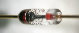
Features of diodes
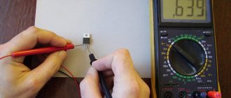
A standard diode is a component of the electrical network and acts as a pn junction semiconductor. Its structure allows current to pass through the circuit in only one direction - from the anode to the cathode (different ends of the part). To do this, you need to apply “+” to the anode and “-” to the cathode. Due to this feature of the product, if you suspect a breakdown, it can be checked with a tester or multimeter.
Various types of diodes.
Today in radio electronics there are several types of diodes: Types of diodes:
- Light-emitting diode. When an electric current passes through such an element, it begins to glow as a result of the transformation of energy into a visible glow;
- protective or regular diode. Such elements in the electrical network act as a suppressor or voltage limiter. One of the varieties of this element is the Schottky diode. It is also called a Schottky barrier diode. Such an element, when connected directly, gives a low voltage drop. In Schottky, instead of a pn junction, a metal-semiconductor junction is used.
It will be interesting Ways to check transistors for performance
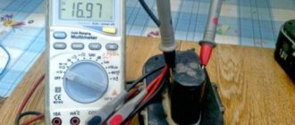
Here is a small selection made up of specific diodes and their corresponding Vf values, which were obtained when testing them with a multimeter. All diodes were previously checked for serviceability.
Table of measurements of diode characteristics using a multimeter.
If ordinary parts and LEDs are used in the vast majority of electrical appliances, then Schottky ones are used mainly in high-quality power supplies (for example, for devices such as computers). It is worth noting that testing a conventional diode and a Schottky diode is practically no different, since it is carried out according to the same principle. Therefore, there is no need to worry about this issue, because the operating principle of both Schottky and conventional diodes is identical.
Schottky diode
Being a component of an electronic circuit, such semiconductor elements often fail. The most common reasons for their failure are:
- exceeding the maximum permissible direct current level;
- excess reverse voltage;
- poor quality part;
- violation of the device operating rules established by the manufacturer.
Moreover, regardless of the cause of loss of performance, failure can be directly caused by either a “breakdown” or a short circuit. In any case, if there is an assumption that the electrical network has failed in the semiconductor area, it is necessary to diagnose it using a special device - a multimeter. Only to carry out such manipulations you need to know how to check the diode using it correctly.
What is a multimeter
A multimeter is a universal device that performs a number of functions:
- measures voltage;
- determines resistance;
- checks wires for breaks.
It will be interesting How to make a power regulator on a triac with your own hands
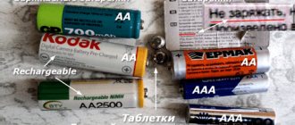
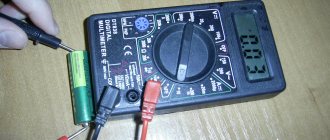
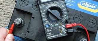
Using this device you can even determine the suitability of the battery.
Checking the LEDs in the lamp.
How to test a diode
After we have figured out the semiconductors of the electrical circuit and the purpose of the device, we can answer the question “how to check the diode for serviceability?” The whole point of checking diodes with a multimeter is their one-way electrical current carrying capacity. If this rule is observed, the electrical circuit element is considered to function correctly and without failures. Conventional diodes and Schottky diodes can be easily tested using this device. To check this semiconductor element with a multimeter, you need to do the following manipulations:
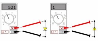
- you need to make sure that your multimeter has a diode test function;
- If such a function is available, we connect the probes of the device to the side of the semiconductor from which the “ringing” will be carried out. If this function is missing, then use the switch to switch the device to 1 kOhm. You should also select the mode for measuring resistance;
- the red wire of the measuring device must be connected to the anode end, and the black wire to the cathode end;
- after this, you need to observe changes in the forward resistance of the semiconductor;
- we draw conclusions about the presence or absence of voltage
The unit can then be switched to check for leaks or high circuits. To do this, you need to change the location of the diode output. In this state, it is also necessary to evaluate the obtained values of the device.
Aspirin and citric acid
To make flux, you can use any substances that have good solvent and antioxidant properties.
It can be:
- alcohols;
- acids;
- vegetable and animal oils.
The simplest flux is prepared by dissolving a tablet or powder of acetylsalicylic acid in water. Acetylsalicylic acid is in the medicine cabinet in almost every home (this is the most common cheap aspirin). It is necessary to dissolve the tablets or powder until the sediment disappears.
Citric acid powder (white granules) is also used.
There are tips to use lemon juice, but it is quite weak, so the effect of its use will be subtle.
When soldering with aspirin or lemon juice, a lot of gas is released, so the room in which they are worked must be equipped with an exhaust hood or well ventilated.
Multimeter
Testing with a tester allows you to determine the serviceability of the diode or confirm its failure. The most commonly used measuring instrument in this area is the multimeter. It is used to measure all the main parameters of electrical circuit components: current, voltage, resistance, capacitance. More expensive models are able to measure the temperature of an object, find out the gain, the capacitance of capacitors, and test the circuit for a short circuit.
Almost all modern types of multimeter can work with both constant and sinusoidal types of electric current. Among the devices on the market, digital and analog types are the most in demand. And although the first type is more popular, the second is still actively used by professionals in their work.
The main advantages of classic analog multimeters are their reliability and low cost (compared to digital ones). However, the minus manifests itself in less accuracy, allowing an error of 1.5-2%.
Digital devices are often used at home. They are more accurate (accuracy up to 0.5%), easy to operate and have greater measurement resolution.
These testers do not require calibration before each measurement and are resistant to vibration.
There is a third type whose device includes both a pointer and a digital indicator.
In addition to the main body, the tester comes with 2 probes with red and black wires.
At the bottom of the instrument panel you can see several connectors:
- “COM” – common, grounded (for black probe);
- “VΩmA” – connector that allows you to ring the contacts, measure the strength and frequency of the current (for the red probe);
- “10 A” – socket for a wire that allows you to measure current up to 10A.
The fourth “°C mA Lx” socket, present on some models, measures additional parameters (temperature, gain and capacitance).
Also on the front panel you can see a rotary disk surrounded by a scale with digital values and marks. Using this dial, you can set the required values, configure them to the desired modes or perform certain functions.
Alcohol, glycerin, rosin
You can get a good alcohol-rosin flux by dissolving rosin in ethyl alcohol. First you need to crush the rosin in a mortar as finely as possible.
Rosin dissolves very slowly in alcohol, and the speed of flux preparation will depend on its thorough grinding. After mixing the alcohol with rosin, it is better to leave the future flux for several hours to complete the dissolution.
You can speed up the process by placing the solution in a sealable glass container and heating it to 80 ℃ in a water bath. Alcohol rosin flux is completely neutral and does not even require rinsing after soldering.
Ethyl alcohol can be successfully replaced with glycerin. This glycerin flux will be thicker than alcohol rosin and will be more convenient to use. In this case, the dissolution of rosin will slow down.
It will be much more effective to first dissolve it in alcohol and then mix it with glycerin. In this case, the activity of the composition will significantly increase, but you will have to wash off the residue from the soldered workpieces.
It’s even possible to make rosin yourself, although it will take time. It is necessary to collect resin from pine trunks in warm, dry weather and melt it.
Can be used for soldering as a flux or its component, rosin for bowed string instruments. It is of very high quality and well cleaned. But its price is much higher than that of soldering rosin.
Analysis of diode test results
- For the most common silicon diodes, the voltage drop is between 0.5 and 0.8 V, indicating that the forward-biased diode is healthy. The voltage drop across some germanium diodes is 0.2 to 0.3 V.
- When a good diode is reverse biased, OL is displayed on the multimeter screen. OL indicates that the diode is operating as an open switch.
- A faulty diode (open) makes it impossible for current to flow in any direction. If the diode is open, the multimeter displays OL for both directions.
- A short-circuited diode exhibits the same voltage drop (approximately 0.4 V) in both directions.
A multimeter in resistance (Ω) mode can be used to perform an additional diode test or, as mentioned earlier, in cases where the multimeter does not have a diode test mode.
The diode is forward biased if the positive (red) test lead is connected to the anode and the negative (black) test lead is connected to the cathode.
- A good forward biased diode should have a resistance between 1000 ohms and 10 megohms.
- When the diode is forward biased, the resistance reading will be high as the current from the multimeter passes through the diode, resulting in a high resistance that is required for testing.
The diode is reverse biased if the positive (red) test lead is connected to the cathode and the negative (black) test lead is connected to the anode.
If the reverse bias diode is good, the multimeter will display OL. The diode is faulty if the readings are the same in both directions.
Testing in resistance mode should be performed as follows:
- Make sure that a) there is no power being supplied to the circuit, and b) there is no voltage across the diode. Voltage may be present in the circuit due to charged capacitors. In this case, it is necessary to discharge the capacitors. Set the multimeter to measure AC or DC voltage as required.
- Turn the dial to the resistance (Ω) measurement position. This function on the controller can be combined with another function.
- Disconnect the diode from the circuit and connect the test leads to it. Write down your result.
- Swap the test leads. Write down your result.
- To obtain reliable results, compare the readings obtained in the resistance measurement mode with the readings for a known working diode.
Choose the right multimeter
Hydrochloric and phosphoric acid
A very effective flux is obtained by dissolving zinc granules in hydrochloric acid. To do this, concentrated acid must be diluted in equal parts with water and the granules placed in a glass container should be poured with this solution. For complete dissolution, zinc will be required at the rate of 412 g per 1 liter of hydrochloric acid.
The dissolution process will be accompanied by a rapid release of hydrogen from the acid, so it is better to prepare in rooms with very good ventilation and away from open fire.
Using flux obtained from hydrochloric acid, steel workpieces are successfully soldered. If you add ammonia to the solution (the same amount as zinc), then this composition can be used when soldering absolutely any metals and alloys.
A good flux is phosphoric acid. It is used when soldering nichrome and stainless steel.
Liquid fluxes are best applied with a thin brush, and should be stored in a tightly sealed glass container with a narrow neck.
Diagnostic methods
The simplest method, which is most often used by radio amateurs, is to check light-emitting diodes with a multimeter for performance using probes. The method is convenient for all types of light-emitting diodes, regardless of their design and number of pins. By setting the switch to the “continuity check, open circuit check” position, touch the leads with the probes and observe the readings. By connecting the red probe to the anode and the black probe to the cathode, the working LED should light up. When changing the polarity of the probes, the number 1 should remain on the tester screen.
To accurately test multi-color LEDs with multiple leads, you need to know their pinout. Otherwise, you will have to randomly sort through the terminals in search of a common anode or cathode. Don't be afraid to test high-power LEDs with a metal substrate. The multimeter is not capable of disabling them by measuring in dial mode.
Testing an LED with a multimeter can be done without probes, using sockets for testing transistors. Typically, these are eight holes located at the bottom of the device: four on the left for PNP transistors and four on the right for NPN transistors. The PNP transistor is opened by applying a positive potential to the emitter “E”. Therefore, the anode must be inserted into the socket labeled “E”, and the cathode into the socket labeled “C”. A working LED should light up. To test in the holes for NPN transistors, you need to change the polarity: anode - “C”, cathode - “E”. This method is convenient for checking LEDs with long and solder-free contacts.
It does not matter in what position the tester switch is located
To check the IR diode in the transistor testing sockets, you will additionally have to use a digital camera (smartphone, telephone, etc.). The infrared diode is inserted into the corresponding holes of the multimeter and the camera is pointed at it from above. If it is in good condition, then IR radiation will be displayed on the gadget’s screen in the form of a glowing blurry spot.
Testing high-power SMD LEDs and LED matrices for functionality requires, in addition to a multimeter, a current driver. The multimeter is connected in series to the electrical circuit for several minutes and the change in current in the load is monitored. If the LED is of poor quality (or partially faulty), then the current will gradually increase, increasing the temperature of the crystal. The tester is then connected in parallel with the load and the forward voltage drop is measured. By comparing the measured and passport data from the current-voltage characteristics, we can conclude that the LED is suitable for use.
Application of fat
Soldering flux can be made from fat with a fairly high melting point. Then at room temperature it will not soften on its own, which will make it easier to work with.
To obtain such a flux, the fat must be melted and mixed with crushed rosin and ammonia in a certain proportion. For three parts of fat by volume you will need the same amount of ammonia and one part of rosin.
For ease of use, the finished flux can be placed in the body of a medical disposable syringe and, if necessary, squeeze out the required amount.
If you are not sure whether a homemade flux is suitable for soldering a part, then you can do a little research. It is necessary to distribute the prepared substance over the surface of a piece of the same metal that is to be soldered.
If, when heated, the flux is evenly distributed over the surface, then it is considered suitable for soldering. If it collects in balls and flows down, then it will be able to provide satisfactory wettability of the part.
The ability to dissolve the oxide film on the metal surface is checked by washing off the applied flux. If the surface remains clean after washing, then the flux dissolves oxides well. On the contrary, if traces of an oxide film or rust remain, then soldering with this flux cannot be performed.
Diagnostics of the serviceability of the zener diode
A zener diode is a semiconductor element that stabilizes voltage in a fairly narrow range. At the same time, different currents, both large and small, can flow through it. The voltage stabilization range of a zener diode is usually limited to one hundred millivolts. Structurally, a zener diode is a diode, and in direct connection it works that way. It stabilizes the voltage when voltage is applied to it in reverse connection. You can check the serviceability of a zener diode with a multimeter in the same way as you can check the serviceability of a conventional diode.
Resistor ringing
The resistor can and should be called. You can ring without unsoldering the element from the board. Ringing an element for a break is done as follows:
- Turn on the multimeter and turn off the device if dialing is carried out without soldering;
- Using a multimeter without taking into account polarity, touch the terminals of the electrical resistor;
- Record the value. If it is equal to one, then this indicates a malfunction and a break has occurred, and the element itself should be replaced.
When not soldering, you should take into account the fact that if the circuit is complex, then you may have to make connections through bypasses and circuits. It is possible to say that an element is 100% faulty only when at least one of its legs is soldered off.
LED device
LEDs are semiconductor devices with an electron-hole junction that creates optical radiation when an electric current is passed through it in the forward direction.
The light emitted by an LED lies in a narrow range of the spectrum. In other words, its crystal initially emits a specific color (if we are talking about LEDs in the visible range) - in contrast to a lamp that emits a wider spectrum, where the desired color can only be obtained by using an external light filter. The emission range of an LED largely depends on the chemical composition of the semiconductors used.
Resistor polarity
Many people are interested in how to find out the polarity of a resistor in order to determine exactly which output contact and where to insert it. In order not to mislead people, we can immediately say that the electric resistor does not and cannot have polarity. This radio element is non-polar. It is believed that resistors are non-polar and can be connected to a printed circuit board in any position of their terminals, in any combination. As with a fuse, you can check the functionality of the resistor in any combination of multimeter contacts and leads, and the order in which it is soldered to the electrical circuits does not matter. It is only important to take into account and check the nominal resistance of the element before soldering, since then in case of malfunctions it will be more difficult to do this due to the influence on the measurement of other elements and circuits of the board.