Field effect transistor - what is it
It includes three main elements - source, gate and drain. To create them, n-type and p-type semiconductors are used. They can be combined in one of the following ways:
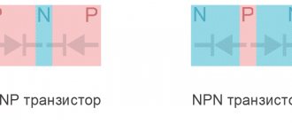
- The drain and source are n-type and the gate are p-type. They are called npn type transistors.
- Those that use pnp polarity. The type of conductivity of each part of the transistor has been changed to the opposite in comparison with the previous version.
Checking with a multimeter
If this part is connected to a power source, then there will be no current. But everything will be different if this is done between the source and the gate or the drain and the gate. It is necessary that a voltage be applied to the gate corresponding in sign to its conductivity type (positive for p-type, negative for n-type). Then current will flow through this part. The higher the voltage applied to the gate, the stronger it will be.
The difference between a field-effect transistor and a bipolar transistor
The transistor will become open provided that a potential difference of the required polarity is applied to the gate. In this case, with the help of an electric field, a channel is created between the source and drain, through which electric charges can move. Other types of transistors control based on current rather than voltage.
The electronic components in question are also called mosfets. This word comes from the abbreviation MOSFET - Metal Oxide Semiconductor Field Effect Transistor (translated this means: metal-oxide-semiconductor field-effect transistor).
Varieties of field beetles
Where to begin?
Before checking any element with a multimeter for serviceability, be it a transistor, thyristor, capacitor or resistor, it is necessary to determine its type and characteristics. This can be done by marking. Once you know it, it won’t be difficult to find a technical description (datasheet) on thematic sites. With its help, we will find out the type, pinout, main characteristics and other useful information, including replacement analogues.
For example, the scanning on the TV stopped working. Suspicion is raised by the line transistor marked D2499 (by the way, a fairly common case). Having found a specification on the Internet (a fragment of it is shown in Figure 2), we receive all the information necessary for testing.
Figure 2. Specification fragment for 2SD2499
There is a high probability that the datasheet found will be in English, no problem, the technical text is easy to understand even without knowledge of the language.
Having determined the type and pinout, we solder the part and begin testing. Below are the instructions with which we will test the most common semiconductor elements.
How does it work
The field-effect transistor differs from other varieties in the features of its device. It can be one of two types:
- with control transition;
- with insulated shutter.
The first of them are n channel and p channel. The first of them are more common. They use the following operating principle.
A semiconductor with n-conductivity is used as a basis. The source and drain contacts are connected to it on opposite sides. In the middle part, on opposite sides, there are inclusions of a conductor with p-conductivity - they are a gate. The part of the semiconductor that is between them is a channel.
You may be interested in this Features of current operation
Transistor with control junction
If a potential difference is applied to the source and drain of an n channel transistor, then current will flow. However, when a negative voltage is applied to the gate relative to the source, the channel width for electron movement will decrease. As a result, the current strength will become less.
Thus, by decreasing or increasing the width of the channel, it is possible to regulate the current strength between the source and drain or isolate them from each other.
In p-channel transistors, the operating principle will be similar.
This type of FET is becoming less common, and is being replaced by those that use an insulated gate. They can be one of two types: npn or pnp. Their operating principle is similar. The first of them will be discussed here in more detail: npn.
In this case, a p-type semiconductor is used as the basis for the transistor. Two parallel strips of semiconductor with a different type of main charge carriers are built into it. An insulator is laid between them on the surface, and a layer of conductor is installed on top. This part is the gate, and the strips are the source and drain.
Transistor device
When a positive voltage is applied to the gate relative to the source, a positive charge is applied to the plate, creating an electric field. It attracts positive charges to the surface, creating a channel for current to flow between source and drain. The higher the voltage applied to the gate, the higher the current flows between the source and drain.
For all types of field-effect transistors, control occurs by applying voltage to the gate.
Transistor open
Possible surprises
The vast majority of malfunctions of MIS transistors are in one way or another associated with breakdown of the gate insulator. This can manifest itself either as a completely measurable leak in the gate circuit, or in a constantly open or, on the contrary, closed state of the channel, without the slightest hint of breakdown of the gate itself.
The destruction of a crystal under overload is often accompanied by such fireworks that there is no need to measure anything there anymore.
What kind of lighting do you prefer?
Built-in Chandelier
Unfortunately, there are also hidden defects, degradation of the quality of the device, caused by a breakdown and which do not appear in any way in the tests described in this article. Recently I myself came across such a defect when working with small field workers (2n7002). What can I recommend here:
You May Also Like
Do-it-yourself surge protector for audio
Checking and selection of field-effect transistors
About resistors
What malfunctions occur
Field-effect transistors can be overloaded with current during testing and, as a result of overheating, become faulty.
Important! They are vulnerable to static voltage. During the work, you need to ensure that it does not fall on the part being tested.
When working as part of a circuit, a breakdown may occur, as a result of which the field-effect transistor becomes faulty and must be replaced. It can be detected by the low resistance of pn junctions in both directions.
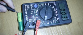
You can determine how efficient a transistor is by testing it with a digital multimeter.
Pin assignment
This should be done as follows (for example, the widely used M-831 model is used, a field-effect transistor with an n-type channel is considered):
- The multimeter must be switched to diode test mode. It is marked on the panel with a schematic diagram of a diode.
- Two probes are attached to the device: black and red. There are three slots on the front panel. Black is set to the bottom, red to the middle. The first of them corresponds to the negative pole, the second to the positive pole.
- It is necessary to determine on the field-effect transistor being tested which outputs correspond to the source, gate and drain.
- Some models additionally have an internal diode that protects the part from overload. First you need to check how it works. To do this, the red wire is connected to the source, and the black wire to the drain.
You might be interested in Features of an electrical energy generator
Checking the diode in the forward direction
A value within the range of 0.5-0.7 should appear on the indicator. If the wires are swapped, the screen will indicate one, which means that no current flows in that direction.
Diode test in reverse direction
- Next, the functionality of the transistor is checked.
If you connect the probes to the source and drain, then the current will not pass through them. To open the shutter. A positive voltage must be applied to the gate. It must be taken into account that a positive potential is applied to the red probe from the multimeter. Now it is enough to connect it to the gate, and the black one to the drain or source, so that the transistor begins to pass current.
Channel opening
Now, if the red wire is connected to the source, and the black wire to the drain, then the multimeter will show a certain voltage drop value, for example, 60. If you connect it the other way around, the indicator will be approximately the same.
If a negative potential is applied to the gate, this will turn off the transistor in both directions, but the built-in diode will work. If the field switch does not close, this indicates its malfunction.
Checking the p-channel mofset is done in a similar way. The difference is that when testing where previously a red probe was used, a black one is now used and vice versa.
Operation of a field-effect MOS transistor
Where can a tester get food?
Position of the multimeter electrodes
The phone adapter provides a current of 100 - 500 mA. Often this is not enough (if you need to check the KU202N thyristor with a multimeter, the unlocking current is 100 mA). Where can I get more? Let's look at the USB bus: the third version will produce 5 A. Extremely high current for microelectronics, stop doubting the power characteristics of the interface. We'll look at the pinout online. Here is a picture showing the layout of typical USB ports. Two types of interfaces are shown:
- The first USB type A is typical for computers. The most common. You will find it on adapters (chargers) of portable players and iPads. Thyristor testing circuits can be used as power supplies.
- The second type B is more typical as a terminal one. Peripheral devices such as printers and other office equipment are connected. It is difficult to find as an initial power source, ignoring the fact of inaccessibility, the authors checked the layout.
If you cut the USB cable, we are sure that many will rush to destroy old equipment and tear off the tails of mice - the +5 volt power wire inside is traditionally red and orange. The information will help you dial the circuit correctly and get the required voltage. Present when the system unit is turned off (connected to an outlet). That's why the mouse's light continues to burn. For the duration of the test, it will be enough to put the computer into hibernation mode. By the way, it is not directly available in Windows 10 (if you go through the settings, you will find it in energy management).
USB Port Layout
Having enlisted the help of the circuit, let's check the thyristor without desoldering. The operating point is set relative to port ground, so external devices will play a small role. Traditionally, the grounding of a personal computer is tied to the case, where the input harmonic filter wire goes. Circuit +5 volts, ground is decoupled from the bus. It is enough to disconnect the circuit being tested from the power supply. To test the thyristor you will need to solder antennae to each terminal. To supply power, a control signal.
Many people squirm on their chairs, not understanding one thing: here we tell you how to test a thyristor with a multimeter, what does it have to do with the LED plus all the bells and whistles? Place the LED, you can - even better - turn on the tester probes and record the current. It is possible to use a low supply voltage, always safer at the same time. As for a personal computer, it provides ample opportunities for testing any elements, including thyristors. The system unit's power supply provides a set of voltages:
- +5 V goes to coolers and many other systems. Actually standard supply voltage. Voltage wires are red.
- +12 volts is used to power many consumers. The wire is yellow (not to be confused with orange).
- – 12 volts are left to ensure compatibility with RS. The good old COM port, through which industrial system adapters are programmed today. Some uninterruptible power supplies. The wire is usually blue.
- The orange wire typically carries +3.3V.
You see, the spread is great, the main thing is the current. The power of computer power supplies fluctuates around 1 kW. Any thyristor will open! It's time to finish. We hope that now readers know how to test a thyristor with a multimeter. Sometimes you have to tinker. The KU202N thyristor mentioned above is equipped with a pnpn structure, non-lockable. After the control voltage is lost, the key does not close. You need to remove the power for the LED to go out. The unlocking voltage is positive. Fits the scheme. The only thing is that the holding current is 300 mA. This is a case where not just any phone charger is suitable for an experiment.
Instructions for dialing without soldering
To check whether the field-effect transistor is working, you need to unsolder it and test it with a multimeter. However, situations may arise when you need several such parts in the circuit and it is not known which of them are working and which are not. In this case, it is useful to know how to test a field-effect transistor with a multimeter without desoldering.
Digital multimeter
In this case, a test without desoldering is used. It gives an approximate result.
Important! After the presumably faulty element has been identified, it is disconnected and checked, obtaining accurate information about its performance. If it functions normally, it is installed in its original place.
Testing without desoldering is performed as follows:
- Before testing the field-effect transistor with a digital multimeter, disconnect the device from the electrical outlet or from the batteries. The latter are removed from the device.
- If the red probe is connected to the source, and the black probe to the drain, then you can expect that the multimeter will show 500 mV. If you can see this figure or one that exceeds it on the indicator, this indicates that the transistor is fully functional. If this value is much less - 50 or even 5 mV, then in this case a malfunction can be assumed with a high probability.
You might be interested in How to measure voltage
With control pn junction
- If the red multimeter probe is moved to the gate, and the black one is left in the same place, then the indicator will show 1000 mV or more, which indicates the serviceability of the field-effect transistor. When the difference is 50 mV, this raises concerns that the part is damaged.
- If the black probe of the tester is placed on the source, and the red probe is placed on the gate, then for a working transistor you can expect 100 mV or more on the display. In cases where the figure is less than 50 mV, there is a high probability that the part being tested is inoperative.
It must be taken into account that the conclusions obtained without soldering are probabilistic in nature. These data allow us to draw preliminary conclusions about the field-effect transistors used in the circuit.
To check, they need to be unsoldered, checked and installed if the functionality is confirmed.
Preparing for work
Bipolar
How to test a bipolar transistor with a multimeter? First of all, you need to find out which of the two subtypes - npn or pnp it belongs to. To do this, let’s remember what a bipolar transistor is.
This is a semiconductor element in which the so-called npn or pnp junction is implemented. Npn is the transition "electron - hole - electron", pnp, respectively, on the contrary, "hole - electron - hole".
Structurally, it consists of three parts - emitter, collector and base. In fact, a bipolar is two conjugated ordinary diodes, in which the base is the common connection point.
In the pnp circuit, the transistor differs from its npn counterpart in the direction of the arrow in the circle - the arrow of the emitter junction. For a pnp circuit it is directed towards the base, for an npn circuit it is directed vice versa.
You need to know this difference to check the bipolar transistor. A Pnp circuit is opened by applying a negative voltage to the base, and an Npn one by applying a positive voltage. But before this, it is necessary to find out which of the contacts of the transistor being tested is the base, which is the emitter, and which is the collector.
The instructions here could be as follows:
- the red (positive) probe is connected to the first terminal that comes across, for example the left one, the black (negative) probe alternately touches the central and right ones. Fix the value “1” on the central one, and 816 Ohms, for example, on the right;
- The red probe of the multimeter is short-circuited with the central contact, the black one - alternately with the side ones. The device displays “1” on the left and some value, say 807, on the right;
- when the red probe of the multimeter contacts the right terminal, and the black probe contacts the left and center, we get “1” in both cases. This means that the base is defined - this is the right contact of the transistor. And the transistor itself is PNP type.
In principle, this is enough to say that the transistor is working. Now, to check its structure and the specific location of the emitter and collector, we short-circuit the black (negative) probe of the multimeter with the base, and the red one in turn with the left and center contacts.
The contact that gives a lower resistance value will be a collector contact (in our case, 807 Ohms). The larger one - 816 Ohms - is the emitter one.
Testing an NPN type transistor occurs in the same way, only the positive contact is applied to the base.
This is a way to test pn junctions between base and collector and base and emitter. The multimeter readings may vary depending on the type of transistor, but will always be within the range of 500-1200 Ohms.
To complete the test, touch the emitter and collector probes. A working element will produce infinitely high resistance, regardless of its type, no matter how you change the polarity. If the value on the screen differs from “1”, one of the transitions is broken, the part is unusable.
Safe work rules
Mosfets are very vulnerable to static electricity. In this case, a breakdown may occur. To prevent this from happening, you need to remove it through testing.
When soldering, a situation is possible where the heat entering the transistor will lead to its damage. In this case, it is necessary to provide heat dissipation. To do this, just hold the transistor terminals with pliers during the soldering process.
Field workers are widely used in modern electronic devices. When a breakdown occurs, you need to know how to check the mosfet. It is possible to find out if it is working if you use a multimeter for this.
IGBT test
IGBTs have an insulated gate and are 3-electrode power semiconductor elements. Here, 2 transients are connected in cascade. in 1 structure: field and bipolar (control and power channels).
You can analyze the transistor on the board and soldered using a similar method. The tester is used to analyze semiconductors (“continuity”, diode icon) or resistance. 2000 Ohm. Then the resistance is measured. in the emitter/gate section straight and back. This way we will identify the short circuit, if there is one. Next, the red wire is connected to the emitter, the black wire is briefly touched to the shutter. The latter is charged with negative voltage, the transistor remains closed.
The next point is to confirm functionality. The gate-emitter input section is charged with positive voltage: at the same time, the red conductor is briefly touched to the gate, and the black conductor is briefly touched to the emitter.
Next, we check the transition point between the calls. and emitter: red wire to the first, black to the other. If a slight drop in value of 0.5–1.5 V is displayed and the value lasts for several seconds. stable, then input. The capacity is intact, the transistor is working.
Testing powerful high-voltage transistors has a peculiarity. If the multimeter voltage is not enough to open the IGBT, then 9–15 V sources are used to charge it at the output, for example, a 9 V Krona battery.
Thyristor testing
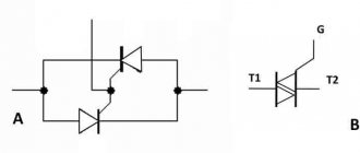
Let's also consider how to ring thyristors; they are in many ways similar to the parts under consideration. There are 3 pn segments, but the mode does not change after the control signal - this is the difference. The structures run alternately like stripes on a zebra crossing. Thyristor is open until the flow value drops “to the holding current”. Such details allow you to create economical circuits.
The multimeter is set to 2000 ohms. To open the thyristor being tested, the black wire goes to the cathode, the red wire goes to the anode. The part opens with both a “+” and “−” charge. In two cases, resistance must be less than "1". The part is open if the value of the control pulse exceeds the holding frame; if it is less, the key is closed.
