Liquid level sensors in the tank allow you to both perform a current measurement of the amount of liquid filled and report when its limit values have been reached. Such devices consist of a sensitive sensor that responds to certain physical parameters, and a measurement, control and indication circuit. Depending on the area of application, devices are used that differ in their operating principles.
The information presented in the article will help you learn about the operating principles of different types of sensors and their areas of application. A brief overview of their advantages and disadvantages will be carried out, and the main manufacturers that have proven themselves on the market will be indicated.
Classification of devices
Liquid level sensors in a tank can be level meters or alarms. The first of them are designed to continuously measure the liquid level at the current time. They use sensors that operate on different physical principles. Further processing of the signals coming from them is carried out by analog or digital electronic circuits that are part of the level gauges. The obtained indicators are displayed on the display elements.
Alarms warn when a certain value of the liquid level in the container, preset by the setting elements, has been reached. Another name for them is water level sensors in the tank to shut off its further supply. Their output signal is discrete. The warning may be provided in the form of a light or sound alarm. In this case, the operation of the filling or draining systems is automatically blocked.
Popular models
The modern market offers many models of alarms . The most popular of them:
- DE-1 (capacitive sensor). Most often, this alarm is used in aggressive environments in the chemical and metallurgical industries. It allows you to control the temperature and level of bulk and liquid substances. Often used in emergency protection installations.
- ESU-1 (electronic level switch). The body of this model is made of high quality steel and fluoroplastic. Most often, ESU-1 is installed in explosive and aggressive environments. The power source is located outside the process environment. The sensor measures the level of oil, alcohol and water. The power supply is made of durable aluminum alloy.
- RU-305 (level relay). This device is designed to monitor the condition of liquid media. Its body is made of special material and can easily withstand temperatures from -50 to +50 degrees Celsius. However, RU-305 must not be used in aggressive chemical environments. Among the disadvantages of this level gauge, consumers note only that it works only in one position, without tilt. Level measurement is carried out by moving a magnet with a float and triggering a reed switch. Measurements have an accuracy of no more than 5 mm.
- SU-100 (level alarm). Sensor for measuring the level of bulk and liquid substances. The SU-100 design contains an electromagnetic relay.
- Rosemount 5600 This radar level sensor allows non-contact measurement of any type of substance. To achieve the most accurate readings, the level gauge must be installed correctly. The device's reading accuracy may be degraded by exposure to electromagnetic radiation. The housing has an explosion-proof design and a display that displays all the necessary information. The Rosemount 5600 can be used to measure tank temperatures. To fully evaluate the capabilities of this equipment, it requires qualified adjustment taking into account the diameter of the pipeline, the length of the level gauge and the distance between the level and the reference point.
It is advisable to purchase complex models only for industrial use. The simplest versions of level meters are suitable for domestic purposes.
Level measurement methods
Depending on the properties of the liquid whose level in the tank needs to be determined, the following measurement methods are used:
- contact, in which there is direct interaction of the liquid level sensor in the tank or its part with the measured medium;
- non-contact, allowing to avoid direct interaction of the sensor with the liquid (due to its aggressive properties or high viscosity).
Contact devices are located in a container directly on the surface of the liquid being measured (floats), in its depth (hydrostatic pressure gauges), or on the tank wall at a certain height (plate capacitors). For non-contact meters (radar, ultrasonic), it is necessary to provide a zone of direct visibility of the surface of the liquid being measured and the absence of direct contact with it.
Types of fill level monitoring products
Liquid level monitoring devices are divided into two main types: contact and non-contact.
Proximity sensors: description
They are used mainly in industrial processes and are divided into ultrasonic devices, capacitive, electrode, operating on the hydrostatic principle, and so on.
Such devices are used not only in water, but also in other environments, including aggressive ones. The circuit includes, in addition to the sensor itself, which is immersed or installed on the walls of the tank, a control controller, which is installed in a separate control unit outside the tank. Such systems are complex and expensive, and, therefore, unprofitable for use in domestic conditions. To control the filling level of the tank with water necessary for irrigation or plumbing, it is more advisable to use simpler and cheaper devices.
Characteristics of contact devices
The most common devices for monitoring the filling of tanks in this type are float-type contact sensors assembled on the basis of reed switches. The devices are simple, reliable and cheap. They are divided according to their location in a container with liquid:
- Vertical arrangement. A rod with a float and a magnet moves along a vertical tube on which the reed switches for turning the pump on and off are located.
- Horizontal placement. Installed in the upper or lower part of the tank wall. As the tank is filled, the float with a magnet attached to it rises on a transverse rod to the reed switch, which switches off the power supply to the pump.
Float sensors for filling control with various design features can be purchased in stores. The choice depends on the specific installation location of the device and operating conditions.
Operating principles
Both level gauges and alarms use different operating principles to perform their functions. The most common types of devices are:
- float sensors for liquid level in the tank;
- capacitive;
- hydrostatic liquid level sensors;
- radar type devices;
- ultrasonic sensors.
Float valves, in turn, can be mechanical, discrete and magnetostrictive. The first three groups of sensors include devices using the contact measurement method, the other two belong to non-contact devices.
Mechanical float sensors
A light float, constantly located on the surface of the liquid in the tank, is connected by a system of mechanical levers to the middle terminal of the potentiometer, which is the arm of the resistance bridge. With a minimum amount of liquid in the container, the bridge is considered balanced. There is no voltage in its measuring diagonal.
As the reservoir fills, the float monitors the position of the liquid level by moving the movable contact of the potentiometer through a system of levers. Changing the resistance of the potentiometer leads to an imbalance in the bridge. The voltage that appears in its measuring diagonal is used by the electronic circuit of the display system. Its analog or digital readings correspond to the amount of liquid in the tank at the current time.
Discrete float sensors
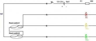
A discrete signal in the form of closing or opening the reed relay contacts is used by the electronic indication and signaling circuit to notify that the liquid level in the container has reached a certain value. Metal contacts, made of a material with low contact resistance when they are closed, are placed in a hollow, insulated glass bulb.
A water level sensor in a tank with a discrete output includes a guide in the form of a hollow tube into which liquid from the tank does not enter. The contacts of one or more reed relays are fixed inside the guide. Their location depends on the case in which it is necessary to receive an alarm when the liquid level reaches a given value.
The sensor float with a small permanent magnet built into it moves along the guide when the liquid level in the container changes. The contact group is triggered when it enters the magnetic field of the permanent magnet of the float. The signal through the wires connected to the contacts of the water level sensor in the reed switch tank is sent to the alarm circuit.
Selection rules
Selecting a level gauge for tanks must take into account a large number of factors. Among them:
- water composition;
- the volume of the container and the material that was used to make it;
- the need to control the maximum and minimum liquid levels or monitor the actual condition;
- the possibility of introducing automatic control into the system;
- switching capabilities of the device.
To select household devices, it is important to consider the capacity volume, control circuit and operating principle.
Magnetostrictive float sensors
Sensors of this type produce a constant signal depending on the level of liquid in the tank. The main element, as in the previous case, is a float with a permanent magnet inside, which takes its position on the surface of the liquid and moves in a vertical plane along the guide.
The inner cavity of the guide, isolated from the liquid, is occupied by a waveguide. It is made of magnetostrictive material. At the bottom of the element there is a source of current pulses that propagate along it.
When the emitted pulse reaches the location of the float with the magnet, the interaction of two magnetic fields occurs. The result of this interaction is the occurrence of mechanical vibrations that propagate back along the waveguide.
A piezoelectric element is attached next to the pulse generator, which records mechanical vibrations. An external electronic circuit analyzes the time delay between the emitted and received pulses and calculates the distance to the float, which is constantly located on the surface of the liquid. The display circuit constantly reports the liquid level in the tank.
Relay operating principle
The relay operates by measuring the fluid resistance between the common electrode and the upper and lower level electrodes. It can be used in electrically conductive liquids such as: tap water, spring water, rain water, sea water, low alcohol liquids, milk, beer, waste water. Not suitable for relay operation: distilled water, gasoline, oil, liquefied gas, kerosene, ethylene glycol.
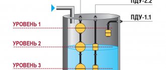
The essence of the operation of the control relay when filling the tank is as follows - if the liquid level drops below the set mark, then the relay, receiving a signal from the minimum level sensor located at the lower mark, turns on the pump and the tank is filled with water again. When the water reaches the upper level, the maximum level sensor signals this relay and then, in turn, sends a command to stop the pump. This way the storage tank never remains empty.
In the same way, you can do the opposite for draining, for example, a basement or cellar, when when the maximum level is reached, the relay will give a command to pump out the water, and when it drops below the minimum, turn off the pump.
Most relays have a time delay function when switching, which increases the service life of the pumps.
Since the switched currents of the relay output circuits are usually small, to control powerful loads in the circuit it is necessary to use a magnetic starter. The level control relay will control the coil of the magnetic starter, and the magnetic starter itself will directly control the load.
The control relay can be controlled by two or three level sensors. They are usually not included in the kit, so you will have to buy them separately. Electrode and float type sensors are usually used.
Capacitive sensors
The operation of sensors of this type is based on the properties of a capacitor to change its electrical capacitance when the dielectric constant of the material filling the space between its plates changes. Coaxial type capacitors are used, which are a pair of coaxial hollow metal cylinders of different diameters.
The latter are the plates of the capacitor, between which liquid can freely penetrate. The dielectric constants of air and liquid media have different values. Filling the reservoir leads to a change in the value of the total dielectric constant of the coaxial capacitor and, accordingly, its electrical capacitance.
The frequency of the oscillatory circuit, in the circuit of which the capacitor is connected, changes in proportion to the change in its capacitance. An electronic frequency/voltage converter monitors this change and displays a value proportional to the degree of filling of the tank.
Capacitive-frequency level switches Baumer CleverLevel
The electrode inside the tip and the sensor body form a capacitor. The material being measured has its own dielectric constant, on which the capacitance value depends. Baumer CleverLevel sensors measure the electrical capacitance between the probe and the wall of the container, in addition, together with the coil located in the contact part, a resonant circuit is formed. As soon as the measured resonant frequency reaches the set response threshold, the sensor output signal switches. INNOLevel alarms are rotary level sensors and are used to monitor the level of bulk products. They work perfectly as full, empty or intermediate level sensors.
Hydrostatic sensors
Another name for such a device is a detector, or pressure transducer. They can be stationary, fixed at the bottom of the container filled with liquid, or portable. In the latter case, the pressure transducers are equipped with a cable of considerable length. This allows them to be used for tanks of different geometric sizes.
The sensing element of a hydrostatic sensor is a membrane that senses the pressure of a liquid column above it. It is configured in such a way that atmospheric pressure does not lead to deformation of the membrane. Based on the pressure at the measurement point, you can determine the height of the liquid column or the degree of filling of the tank.
The amount of membrane deformation is converted into a proportional electrical indicator, which is then used to display the level of liquid in the reservoir. Corrections are applied that take into account the density of the measured medium and the acceleration of gravity at the measurement point.
Radar type sensors
The container liquid level sensor uses a non-contact measurement method based on the properties of this medium of any density and viscosity to reflect an electrical signal. The frequency of the emitted signal from a radar located above the surface of the measured liquid level changes according to a linear law.
Reflected from the surface, it arrives at the receiving device with a delay determined by the length of the path traveled. Thus, there is a difference between the frequencies of the two signals. Based on the frequency shift, the radar analyzing device determines the path traveled by the signal or the level of the reflecting liquid relative to the location of the radar.
Ultrasonic level sensors
The measurement scheme used for sensors of this type corresponds to that discussed in the previous section of the article. The location measurement method is used in the ultrasonic wavelength range.
The received data determines the time difference between the signals emitted by the transmitter and the signals received by the receiver. Using data on the speed of propagation of ultrasound in the space above the surface of the liquid, the analyzing device determines the distance traveled by the signal or the level of liquid in the reservoir.