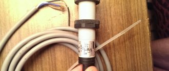
Last year I made a septic tank in my country house with my own hands. The drainage system works almost perfectly, but I just miscalculated the volume of the storage tank. The tank is filled too often, and the moment the tank overflows is often an unexpected and unpleasant surprise, leading to the inability to use the sewer system. In order to be able to call a sewage disposal truck in a timely manner, I decided to assemble and install a small device in the septic tank that would give a signal when the tank is full. The circuit diagram of a water level sensor in a tank with your own hands is quite simple, and then I will tell you what was done and how.
Source: allaboutcircuits.com
Materials and tools
As in the manufacture of his other “crafts,” the assembly of the indicator was almost entirely carried out using radio components and other necessary elements that were already in use. To independently manufacture such a system, I used parts in the following quantities:
- Three-pin reed switch: 2 pcs.
- Low power LEDs: 3 pcs. (red, yellow and green).
- Plastic clamps: 2 pcs.
- Neodymium magnet.
- Heat-shrinkable cambric 40 mm.
- Low voltage five-core wire.
- Connecting sleeve 50 mm: 2 pcs.
- Rivets: 10 pcs.
- Plugs 50 mm: 2 pcs.
- Furniture profiles made of plastic.
- Resistor 680 Ohm.
- Four-pin plug.
- Switch button.
I used a 3.7 volt battery as a power source, but you can also use two AA batteries connected in series.
Source hobmodels.ru
Soldering batteries can lead to boiling of the electrolyte and rupture of the case, therefore, when using 1.5 V products, it is recommended to purchase and install a special box to which contact wires can be soldered without problems.
Do-it-yourself assembly of the water level indicator in the tank was carried out using the following tools:
- Soldering iron.
- Drills.
- Construction hair dryer.
- Thermal gun.
Also, when installing the alarm system, you cannot do without a screwdriver and pliers.
Recommendations for protection
If you connect a reed sensor with your own hands, then you need to consider the following points:
- It is necessary to install the thinnest metal plate. It is placed between the magnet and the reed sensor for protection.
- Magnetic and reed switch sensors must be installed so that they are directed towards each other. The distance should be short.
Making a level sensor: step-by-step instructions
I assembled the water level indicator in the tank using LEDs with my own hands in the following sequence:
- I attached three-pin reed switches to a plastic clamp using a heat gun. My distance between the elements was about 4 cm.
Source freeseller.ru
- I soldered the wires according to the diagram. After the contacts had cooled, the wire connections were treated with silicone to protect them from moisture.
- Then the clamp was placed on the plastic pipe coupling so that the upper part could easily move relative to the stationary pipe.
- As a float, I decided to use a second coupling, into which plastic plugs were inserted on both sides.
Source otlad.ru
- At the next stage, I used a hair dryer to heat up the plastic profile and wrap it around the float. The free end of this element was secured to the lever using plastic rivets.
- In a similar way, a lever made of a plastic profile was attached to the coupling.
Source otlad.ru
- A neodymium magnet was then attached to the lever. For reliable installation of this element, you should use parts that have a hole in their design. I used a product from an old computer hard drive, but you can use store-bought products that already come with mounting holes. Wide magnets should be a priority, because in this way it will be possible to ensure smooth activation of the sensor operating modes.
- Next, I decided to check the functionality of the indicator system. By connecting the connector to the wires that were connected to the current source and the LEDs and moving the lever up and down, I made sure that the LEDs were switched on in series.
The water level sensor for the barrel was installed on the drain pipe of the septic tank with your own hands, after which the contact wires and battery were also connected.
Varieties
The device operates on the principle of opening or closing the line transmitting electricity. The magnetic flux intensity determines the closed or open position. It is noteworthy that it does not matter where the magnetic field originates from. It can appear either from an electromagnet or a permanent magnet.
Magnetization in the device begins to occur when the power lines are affected. After this, the elastic force is overcome and attracts the contacts to each other. As a result, the circuit is closed.
The sensor will remain in this state as long as the magnetic field remains. After the influence of the power lines ceases, the contacts open. For the next short circuit to occur, the field around the device must be created again.
Based on this, experts consider the reed switch to be a switch.
Closing
Closing devices, by their operating principle, are constantly in an open state. For them, this is a normal static position, and the contacts will not connect to each other.
Principle of operation
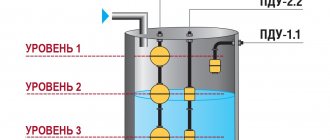
The circuit diagram of a self-made water level switch is very simple. When the septic tank is not yet filled, the float is in the lower position, and the neodymium magnet is opposite the first reed switch. In this position, the reed switch contacts will be forcibly closed to pin 3, through which the electric current is directed to the green light bulb.
As soon as the tank is filled, but the liquid level has not yet reached critical values, the float will rise slightly and the effect of the magnetic field on the contacts of the first reed switch will stop. In this position, the “standby” mode will be activated, in which both reed switches will operate in a state where the current through them passes to contact 2.
After the liquid level in the tank rises, the float will move upward, and the neodymium magnet will align with the second reed switch, in which the contacts will switch to contact 3, through which electric current will flow to the red LED.
Advantages and disadvantages
Reed sensors have their advantages and disadvantages. The advantages include:
- There is no chatter in the contacts. This is true for those whose terminals are moistened with mercury.
- Compared to classic relays, the sensors are characterized by high response speed.
- The sensor is considered durable and is not susceptible to physical shock (for example, due to careless handling or falling).
- This type of sensor does not create noise.
- The contacts burn poorly because they are located in a vacuum or inert gas. This also applies to those cases where a short circuit with erosion occurs with the occurrence of a spark.
- The price is affordable for everyone, since refractory or precious metals are not used in production.
- Small size compared to classic relays.
- Compared to open contacts, they are a bit heavy.
- Response speed is limited.
- You need to create a magnetic field.
- There are cases when the contacts remain in a closed state and cannot be removed from it.
- External magnetic fields affect them.
Advantages of a homemade LED sensor
The advantages of a do-it-yourself liquid level sensor made from “free” parts are the following:
- High reliability. Thanks to the use of reed switches, which are electrical contacts hermetically sealed in a bulb, operation in conditions of high humidity does not negatively affect the efficiency of the device.
- Lightweight design. Due to the fact that almost all the elements used in the manufacture of a homemade sensor are plastic, they have minimal impact with their mass on the polymer pipe on which the device is mounted. Plastic is practically not subject to corrosion, which is also one of the most important advantages of the product.
Source freeseller.ru
- Almost all parts can be obtained free of charge. In my case, the pipe elements were left over after laying the sewer system, I soldered the LEDs from the old radio, and the reed switches were purchased earlier on Aliexpress for the purpose of making a contactless relay for switching the operating mode of the electric motor.
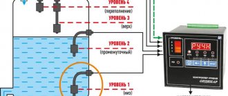
Do-it-yourself circuits for monitoring the water level in a tank may contain a larger number of reed switches. For example, if it is necessary to more accurately determine the liquid level in a tank, then a gradual light transition from blue to red from 5 to 7 parts can be used.
In this video, watch how best to choose a float for a septic tank full sensor:
Description and purpose
A reed switch is an electromechanical type device that opens or closes electrical contacts. This occurs due to the magnetic contact field generated by the electromagnet. A permanent magnet can also do this.
Reed switch is translated as sealed contact. This is due to its design. Its components are ferromagnetic plates, which are sealed in a glass capsule. It is filled with inert gas, along with two output contacts.
Thanks to the shell, the impact of external factors is minimized, while the device can function normally.
The flask may contain dried air, nitrogen and any other inert gas. In addition, it can be pumped out to create a vacuum. This is done to increase the level of switching voltage.
Reed switch sensors are used in various systems and devices:
- Household meters.
- Keyboards in industrial equipment and synthesizers. The occurrence of a spark from them is excluded. That is why they are widely used in the production of explosive things (where there are dusty fumes or flammable substances).
- Equipment for medical institutions.
- Systems that protect and control the situation, operating on an automatic principle.
- Telecommunication systems.
For security systems, devices made from a magnet and a reed switch are relevant. They signal the closing and opening of doors.
It is worth noting that reed relays are common, which consist of a wire winding and a contact sensor. Such a system has significant advantages: moisture resistance, easy use, no moving parts.
Reed switches are used to protect electrical installations from overloads.
Connecting a reed switch to arduino
The sensor is ready, all that remains is to connect it to the Arduino and write simple firmware. In fact, the entire sensor consists of one reed switch and a magnet, everything else is just a housing. Therefore, the connection is simple: the reed switch has no polarity, so all you need is to connect one electrode to 5V, and the other to any digital or analog pin. And don’t forget to pull the reed switch to ground through a resistor with a nominal value of 10 kOhm. Everything is the same as with an ordinary button. But just in case, for clarity, below is the connection diagram.
Examples of practical use in everyday life
The reed switch allows you to control the lighting in the corridor. For example, using a reed switch, the light can turn on automatically when the front door is opened. After a few minutes it will turn off. At the same time, when the lighting level is normal - during the day, the light will not turn on in the corridor. It is also used in home and security alarms as a detector.
The most common type of reed switch is the open reed switch. Each contact in the glass container is a flat wire. The contact surfaces are plated with gold, palladium, radium or silver, which helps reduce resistance and protects the contacts from corrosion. The space of the glass flask is filled with hydrogen, argon or nitrogen, or simply represents a vacuum space, which also helps to increase the anti-corrosion properties.
Source
DIY water level indicator
Water level indicator diagram.
The scheme is very simple, but it works great. At the end of the article there will be a video that clearly shows the operation of this water level indicator, which we will make together with you. To get started, let's collect the parts we need to make the device.
Parts for making a water level indicator circuit.
We will need: ULN2004 microcircuit or similar, a contact pad for installing the microcircuit on the board. With such a pad, there is no risk of overheating the legs of the microcircuit with a soldering iron or damaging its internal structure with static electricity. And circuit repair, if necessary, is reduced to a few seconds. It is enough to remove the burnt microcircuit from the socket and insert a new one in its place. A complete benefit, especially for not very experienced radio amateurs. Resistors R1 - R7 - 47Kom. R8 - R14 - 1Kom. LEDs of any color of your choice, with a diameter of 3 - 5 mm. Capacitor 100Mkf 25v. Terminal blocks of any type, or you can do without them at all, but the ease of use of the device will decrease somewhat. Any development board, as long as all the components fit. I use such boards because I don’t want to bother making a printed circuit board, it’s just more convenient and familiar to me.
We have all assembled the components and are ready to begin manufacturing our device.
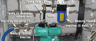
This is the first ready-made element of a future water purification system from iron, bacteria, all sorts of harmful impurities and other “poop”. The system has been working at my home for almost three years now, it has proven to be reliable, convenient, and in general I like it. I am completely satisfied with the quality of the water. But the time has come for modernization. New requirements have appeared (for me), I want more convenient service, I want all the information about the operation of the system to be constantly in front of my eyes. I built the first water purification system without any experience and made some mistakes, which I will certainly write about in future articles, but overall there were only two minor breakdowns. I was to blame for one breakdown, and for another it was a poor quality component (again I was to blame, I saved a little and bought the wrong thing).
All equipment will be modular (this increases the possibility of modernization and simplifies repairs), as cheap and simple as possible, so that many can repeat it.
I’ll tell you why white wires are needed in one of the following articles. The water level indicator (alarm) is ready.
The cable that goes to the level sensors can be any eight-wire signal cable; they are now sold in all sorts of different stores that deal with alarms and electrical systems. The cross-section of the cores and the length of the cable do not play a special role. There are cables that are very thin and cheap.
How to make level sensors needs to be thought out and manufactured according to the place of application. It is best to make the sensor contacts from stainless steel. The positive common electrode needs a massive one. I made it from a small stainless spoon, the electrode works fine and is not at all susceptible to electrochemical dissolution. The places where the wires are soldered to the electrodes are best insulated with the help of any glue gun (reliably preserved from dissolution).