Among the total volume of pumping equipment produced, console-type pumps account for 65%. These units have gained popularity due to their very simple design, ease of repair and maintenance, and fairly high efficiency.
Scope of application and classification
Cantilever-type pumping equipment is designed to work with clean and lightly contaminated liquids that do not contain solid mechanical inclusions. The maximum content of abrasive substances in the working environment is 0.1%, their size is no more than 0.2 mm.
The use of such pumps is widespread in the following areas:
- municipal water supply;
- irrigation and watering systems;
- public utilities;
- Fire safety;
- production lines;
- chemical industry.
Cantilever pump in operation
Depending on the design, cantilever pumps are classified into 4 types:
- K - standard version: horizontal body, connection of the wheel and drive via an elastic coupling.
- KM are cantilever monoblock pumps in which there is no separate impeller shaft (the wheel is fixed on the electric drive shaft).
- KMP is a booster cantilever monoblock unit, designed for operation in public water supply systems, practically no different from the KM class.
- KML is a linear console with a vertical axis of the impeller and a linear layout of the intake and supply pipes.
The most common are class “K” pumps, which are equipment for general industrial use.
Design and operating principle
The main functional unit of centrifugal cantilever pumps is the impeller, through which the working medium is pumped. Depending on the number of wheels, the units are classified into single and multi-stage.
The impeller has the shape of a drum consisting of two parallel disks, which are connected by internal plate partitions. The wheel installed inside the working cavity receives torque from the shaft on which it is mounted coming out of the electric motor. The wheel is fixed on the shaft using a bearing unit, protected from contact with liquid.
The internal cavity of the housing in which the drum is located has two openings - suction and supply. The principle of operation of the mechanism is quite simple - during operation, water enters the cavity through the suction hole and is captured by the blades of the wheel, which, rotating, accelerates the movement of the liquid and throws it out through the supply hole.
Cantilever pump device
The pump layout is shown in the diagram, which shows:
- Case cover.
- Frame.
- Seals.
- Impeller.
- Bearing unit.
- Oil seal packing.
- Protective sleeve.
- Stuffing box.
- Rotation shaft.
- Support bracket.
- Rotation bearing.
All pumps with a power of more than 10 kW have a system for unloading the drum from axial forces; it is not provided for in low-power units. Sealing of the housing from the inside is ensured by sealing rings (3), which prevent the liquid from passing into the low-pressure zone, which increases the overall efficiency of the pump. The rotation shaft is sealed with a stuffed oil seal (8); a protective sleeve (7) is also provided, which prevents abrasion of the shaft in the area of contact with the oil seal.
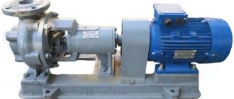
Horizontal cantilever pump
The functional purpose of the pump directly affects the materials used to manufacture its spare parts. Thus, in general industrial equipment, impellers made of alloy steel are used, less often - made of gray cast iron. Pumps for the chemical industry are equipped with drums made of special alloys that are resistant to the pumped medium.
The body of the unit can be made of cast iron, steel, aluminum or stainless steel. The material of sealing rings, seals and cuffs is selected based on their temperature of the working environment. The most common console pump of class “K” is designed to work with liquids with temperatures up to 85
0
.
What are the features of the K8-18 cantilever pump? (video)
This is interesting: Pumping stations without a hydraulic accumulator and with a hydraulic accumulator: operating principle, design, advantages and disadvantages
Shaft and bearings
How to create beautiful flower beds and flower beds at your dacha with your own hands? (100 photos + video)
Whatever type of wheel is used, it is mounted on a rotating shaft. The shaft must be secured in the housing with bearings in one of 2 ways:
- Console
- Symmetrical
Cantilever fastening
When the shaft is cantilevered, the impeller is fixed at one end and the bearings at the other.
This design places the suction and discharge ports perpendicular to each other, and the suction port directly in front of the center of the wheel.
Such pumps are called end suction pumps. They are widely used because they are cheap and easy to produce, but they have one drawback related to the path of fluid movement.
During pump operation, a low pressure zone is created in the suction port.
There is a high-pressure zone at the outlet of the wheel, from which the energized fluid enters the spiral casing.
Fluid flows towards the rear plate in open and semi-open wheels, which completely destroys the pressure balance. As a result, an axial force or load occurs - pushing the wheel towards the suction hole.
This can be compensated for by installing stronger bearings or drilling holes in the wheel plate to equalize the pressures. But these are not effective methods.
Symmetrical mounting
A more effective solution is to place the shaft on bearings on both sides. This is called symmetrical design.
Shaft support is improved not only by the placement of bearings on both sides, but also by the ability to use symmetrical closed wheels with double suction.
Since there are the same high and low pressure zones on both sides of the wheel, this successfully eliminates loading forces due to the balance of pressures. This design also has another advantage. The suction and discharge ports are located parallel to each other on opposite sides of the pump, and the housing is axially divided.
By simply unscrewing the bolts and removing the cover, the service technician can access the rotating part of the pump inside without removing the entire pump from the system.
Due to the separate axial design, pumps with a symmetrical bearing arrangement are called split-casing pumps.
All of these, of course, are very good reasons to install such a pump in your mine right now. But there are some disadvantages. Because maintenance operations and sealing requirements are more complex for split casing pumps than for end suction pumps. They are also more expensive.
Repair
Overhaul of the pump is carried out after the installed resource of the unit has been exhausted. The optimal duration of the operating period is determined by the model and brand of the pumping unit.
<
The most common problems during operation are:
- No pressure after startup. Similar problems can arise as a result of clogging or the formation of voids in the impeller, which must be filled with liquid;
- Poor productivity may be due to wear on the impeller or increased resistance in the feed hose;
- Wear of insulating devices or a significant increase in pressure in the system can cause leakage;
- Bearings may overheat due to changes in shaft alignment or insufficient lubrication;
- Increased vibration and high noise during operation may indicate that the cavitation reserve is increased, the pump is not tightly fixed on the concrete platform, or the bearings require replacement.
During operation, cantilever pumps require constant maintenance, as well as preventive repairs approximately every 3 months.
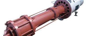
Booster pumps
Most vertical pumps are of a booster design. This is a type of design in which the pump is subjected to operating conditions similar to those found in a well. To make this possible, the body of the booster pump is placed in a cylindrical container made of galvanic or stainless steel filled with water.
They are connected using a flange adapter and centered with bolts located on the outer perimeter. This solution makes the structure unusually stable - such a unit can be placed either vertically or horizontally.
Advantages of boosters
Pumps of this type are most often used for assembling pumping units for industrial purposes, since their performance and pressure are not inferior to the characteristics of well pumps. It is simply impossible to achieve, for example, a head of 800 m with a supply of 1000 m3/hour from a horizontal surface pump.
Installation with horizontal booster pumps
- Such indicators, of course, are not needed everywhere. But in fire extinguishing systems, there is practically no alternative to booster installations, because buildings can be quite tall, and it is not always possible to get close to them during a fire. In such cases, it is high pressure that saves the situation.
- Boosters are also indispensable for supplying drinking water to objects located high above sea level, for example, in the mountains. And, despite the fact that the price of such installations is quite high, during operation it quickly pays for itself due to economical energy consumption.
If we compare their costs with other pumps of similar power, the savings will be no less than 50-55%. The use of booster installations to provide water to facilities under construction makes it possible to reduce their cost, since energy always accounts for the lion's share of costs.
Liquid pumping technology
The cantilever water pump is a reliable and high-quality unit. It is used for pumping cold or hot water. The efficiency of these devices is 60-80%, but this depends on the engine power and model. The cantilever monoblock pump has both an oil seal and a mechanical seal.
There are two types of cantilever pumps: vertical and horizontal. In a horizontal cantilever unit, the axis of rotation is horizontal. The location of the rotation axis affects the supports and devices inside the unit. The axis of rotation can be horizontal, vertical, or at an inclined horizon.
K-type pumps
Enterprises use electric water pumps of type K (for example, they use a K 8 18 console pump, a K 20 30 pump, etc.). The running gear of cantilever water pumps has a shaft that rests on a bearing on which the impeller is located. It also has a compensation chamber, which helps to avoid water leakage under high pressure.
The front and rear seals prevent liquid from penetrating in and out. Leaks are not removed through the oil seal and provide additional lubrication, which protects the engine well from overheating. The shaft located above the oil seal is protected from wear by a bushing.
Monoblock pumps
The difference between monoblock cantilever pumps is that the impeller is built into the end of the shaft. These powerful units are called KM type pumps. These units are used in engineering enterprises. Among the disadvantages of this powerful unit, it is worth noting that it is large in size, heavy in weight and has a very short-lived seal, as a result of which the unit requires constant inspection and regular repairs. And the repair of the KM electric pump is longer, more labor-intensive and expensive than that of the K type.
The most common monoblock units: KM 50 32 125, KM 80 50 200, KM100 80 160, KM 65 50 160.
Monoblock cantilever pump
The electric pump KM 65 50 160 is characterized by very small dimensions and low weight. This technique can be integrated into a ready-made working system.
Technical characteristics of KM 65 50 160:
- productivity – no more than 30 cubic meters;
- pressure – up to 30 m;
- engine power – 5.5 kW;
- permissible temperature of the working fluid is from -20˚С to 100˚С.
By 20 30
The centrifugal console pump K 20 is equipped with a horizontal axial supply of the working medium. K 20 is designed for pumping liquids in stationary conditions. The shaft seal is single mechanical, single or double stuffing box.
The K 20 30 unit has a wide range of uses: heating pipelines, water pipelines, pumping stations for industrial, rural and urban water supply. The K 20 unit is not used in fire or explosive areas.
Technical characteristics of K20 30:
- head – 30m;
- flow – 20 m³/h;
- power – 4 kW;
- rotation – 3000 rpm;
- weight – 78 kg.
K 45 30
According to technical characteristics, the K45 electric pump is horizontal and equipped with a closed wheel. The single-stage pump and electric drive are connected by a coupling and are located on a common frame.
The body of the K 45 unit is made of cast iron. The rotor rotates counterclockwise in bearing supports. There is an arrow on the K 45 casing that shows the direction of rotation of the rotor.
The flow parts of the K 45 unit are made of cast iron. To protect the shaft from leakage, a seal is used. The leakage rate through the seal is no more than 2 l/h.
The K 45 centrifugal unit can easily be replaced by 3K-45 30 and 3K-9 water pumps.
K 65 50 160
The K 65 device is designed to pump clean water. The material for the manufacture of strong parts of the K 65 50 unit is SCh20 cast iron, the shaft is steel 45.
The K 65 device has special holes to drain leakage through the seal. And the shaft seal is a stuffing box with packing or single.
K 80 50 200
The K 80 unit is a cantilever horizontal single-stage pump. K 80 is designed to move water up to 85˚C.
The console device K 80 50 200 is produced in two types of shaft seal: single (“C”) and double stuffing box, which is designated “SD”. A single seal helps the K 80 50 200 unit to pump water t no more than 85˚C. The double seal allows you to work with hotter liquids, from temperatures up to 105˚С, and with a mechanical seal - no more than 140˚С.
Cantilever pump to 200
The K 80 50 200 unit can ensure uninterrupted operation at absolute inlet pressure. In K 80 50 200, the permissible leakage of water through the seal is no more than 2 l/h. This unit can be replaced with a console unit K 80 65 160.
K 100 65 200
Electric pump K 100 65 200 is centrifugal, with a one-way supply of working fluid to the wheel; the horizontal pump and motor are located on a common plate.
Impeller K 100 65 200 is a closed type with one-way inlet. The unit is equipped with an axial liquid supply. Supports for the rotor are radial and angular contact ball bearings.
In the upper part of the K 100 65 200 body there is an air outlet hole, which is closed with a plug. In the lower part there is a hole for draining water when the unit is stopped, which is also closed with a plug.
The electric pump K 100 65 200 can be replaced with the console unit K 150 125 250.
Console self-priming pump AL-KO Jet 3500 Classic (video)
An example of a pump unit symbol:
KM80-50-200 a-5 UHL4
- KM
– pump type – monoblock console pump, centrifugal - 80
– diameter of the suction inlet pipe, mm, - 50
– diameter of the pressure outlet pipe, mm, - 200
– nominal diameter of the impeller, mm, - a
– first turning of the impeller, - 5
– designation of a single mechanical seal, - UHL4
– climatic version and placement category.
The design of a cantilever pump - what does the device consist of?
Their design and the materials from which they are made depend on the areas of use of the units. Pumps used in industry are equipped with steel wheels, and in some cases with cast iron elements. Devices used in the chemical industry are equipped with drums made of various alloys that are resistant to aggressive substances.
The unit body is made of aluminum, stainless steel or cast iron. Oil seals, rings and cuffs are made from materials designed for the temperature of the pumped liquid.
Design features of console pumps K and KM
Pumps K and KM are manufactured in accordance with GOST 22247-96 “Centrifugal cantilever pumps for water...”, which regulates the main parameters and dimensions of pumping units. GOST 22247-96 provides for various designs of cantilever pumps (Section 3), including:
- console horizontal, designated K in this standard;
- monoblock horizontal, designated KM.
- Pump design K
Structurally, the K series cantilever pump is a single-stage horizontal centrifugal pump with supports on the housing and on the stand. The electric motor and pump are mounted on a common frame or foundation plate. Torque from the electric motor shaft to the impeller shaft is transmitted through an elastic coupling protected by a protective casing. The pumped water is supplied horizontally along the axis of the pump and discharged tangentially upward.Note! In the current practice of operating industrial pumps, cantilever pumps are not entirely correctly identified exclusively with K-series pumping units, which are used for pumping clean cold or hot water. In fact, the group of cantilever pumps is classified according to design characteristics (see drawing below) and includes pumps that pump not only water, but also other liquids. For example, NK cantilever pumps are used in the oil industry, AH – in the chemical industry, SM cantilever pumps are designed for pumping wastewater, etc.
The figure below shows a drawing of a horizontal console K series pump, which shows the following main structural elements:
- pos. 1 – impeller;
- pos. 3 – cover with an axial inlet for water supply and a flange for connecting the pump to the water supply pipeline (type A);
- pos. 4 – shaft;
pos. 2 – spiral outlet-housing with a flange for connecting the pump discharge pipe to the pipeline (type B);
It is important! The impeller (item 1) is mounted on the cantilever part of the shaft (item 4), as a result of which this design is classified as a cantilever pumping unit.
- pos. 5 – bearing support (2 pcs.);
- pos. 6 – support bracket, which serves as a housing for placing bearing supports and performs the functions of an oil bath;
- pos. 7 – fitting;
- pos. 8 – oil release ring;
- pos. 9 – support post;
- pos. 10 – fairing.
- Design of the KM monoblock pump
In KM pump units, the pump impeller is installed at the end of the elongated electric motor shaft, as a result of which the KM product is a monoblock that does not require a drive to transmit torque from the electric motor shaft to the impeller shaft. The principle of operation of the KM pump monoblock is similar to the operation of the K series equipment, however, the following advantages are noted for the design of KM pumps compared to K pumps: - more compact dimensions;
- no energy losses in the coupling and bearings;
- There is no need for alignment/alignment of the pump and motor shafts.
fewer parts;
This is interesting: Vertical pumps: types, design, features of application and maintenance
Rules for installing pump equipment type KM
Centrifugal pumps design and principle of operation
The installation location of the console-type unit must meet the following parameters:
- The KM pump is installed in a place where there is a normal approach for maintenance and installation.
- The parts of the pipeline connected to the inlet and discharge pipes are fixed on separate supports. This is necessary to ensure that the load from the pipeline is not transferred to the pump flanges. It is also necessary to install temperature compensators on the inlet and pressure parts of the pipeline.
- The pipe on the suction side is installed with an inclination towards the intake tank in the most direct and shortest way to create cavitation-free operation of the pump.
- The check valve is installed at the pump outlet.
- To control the liquid pressure, pressure gauges and mono-vacuum gauges are installed at the inlet and outlet of the electric pump.
- If a barrier fluid is needed for the operation of the console mechanism, then it is supplied. Drainage outlets are also required to ensure the removal of fluid leaks from the pump.
KM pumps in industrial environments
After installing the console device, the entire pipeline is checked for strength and tightness. To do this, create a test pressure corresponding to the system parameters. They also check the operation of the rotor: there are no jams during rotation and contact with moving or stationary parts. Before starting the pump for the first time, all taps must be closed. In this way, their serviceability and the pressure level on the pressure gauges are checked.
Operating principle, installation
The principle of operation of a cantilever pump is not complicated and is determined by the main design features. When the electric motor is turned on, the blades on the impeller begin to rotate rapidly. Due to this, strong pressure is built up and the liquid is pumped, being drawn into one hole and squeezed out of another, located on the opposite side of the disk. The speed of pumping water increases significantly when the wheel begins to rotate faster.
However, excessive acceleration can cause cavitation due to reduced inlet pressure levels. More specifically, the cavitation process is caused by vapor formation accompanied by condensation of air contained in the working fluid. For this reason, selecting the appropriate cantilever pump should always be the responsibility of an experienced professional.
To operate a cantilever pump, a reliable base is required in the form of a concrete foundation, which is approximately 20 cm larger in size than the pump housing. The thickness of the base must be at least 20 cm. The frame of the pumping device must be firmly fixed to the base. For this purpose, special anchors are often used. A special gasket is placed between the foundation slab and the device body to absorb vibration. On the nozzles of the pumping device in front of the pipe structures, it is necessary to install shut-off valves, as well as counter flanges, which ensure a sufficiently reliable connection of the nozzles and pipe structures.
Operating principle
The principle by which a cantilever-type centrifugal pump operates is quite simple.
- When the power supply to the drive motor is turned on, the impeller equipped with blades begins to rotate.
- When passing through the area of the internal chamber where the inlet pipe of the pump is located, a vacuum of air is created in it, which facilitates the suction of the liquid medium through the pipe.
- The liquid entering the cantilever pump begins to move along with the impeller blades, which ultimately leads to an increase in the pressure of the pumped medium in the area of the discharge pipe and its pushing through it into the pipeline system.
When the impeller of a cantilever pump equipped with blades rotates, a centrifugal force is created, due to which the flow rate of the liquid pumped by such a device increases.
Operating principle of a cantilever pump
Meanwhile, it should be borne in mind: if a cantilever pump intended for equipping a water supply system is selected incorrectly, then too high a rotation speed of its impeller with blades can lead to the creation of insufficient air pressure in the inlet pipe, which will reduce the efficiency of the equipment. . When using a centrifugal cantilever pump, the impeller of which rotates at too high a speed, the pumped liquid medium in the working chamber transforms into steam, which then condenses. This leads to a phenomenon called cavitation. That is why you should have a good understanding of how to choose a cantilever pump to equip water supply systems with certain technical characteristics.
Sectional view of a cantilever chemical pump
K 18 units - design and technical characteristics
Equipment of this type is used in production where pumping water in medium and small volumes is required.
These cantilever water pumps consist of a running gear, the design of which includes a shaft. The shaft together with the support wheel is located on a bearing. The pump device also includes a compensation chamber, designed to protect against overflow if the liquid pressure is too high.
To prevent liquid from penetrating into and out of the pump, the unit is equipped with a non-return valve. Thanks to the oil seal, leaks do not escape outside and serve as additional cooling, protecting the device motor from overheating. The shaft located above the oil seal has special wear protection in the form of a bushing.
Basic operating elements
Pump with two working chambers
The single-stage centrifugal pump has the following design and operating fittings:
- Receiver check valve. As a rule, it is equipped with a special mesh, with the help of which various types of impurities included in the working fluid are filtered. The main purpose of the valve is to retain the pumped liquid inside the suction pipe.
- Valve. It is installed on the pressure pipeline. With its help, bringing the pump into working condition or stopping it. In addition, the valve is used to control the pressure of the liquid.
- Vacuum gauge. It is used to measure the vacuum level on the suction side. In most equipment models, a vacuum gauge is mounted between the unit body and its valve directly on the pipeline.
- Tap. When filling liquid with a tap, air is released from the liquid.
- Pressure gauge. It is installed on the nozzle of the pressure mechanism. The main purpose of this mechanism is to measure fluid pressure.
- Safety valve. Performs a protective function for the equipment body against possible hydraulic shocks. The valve is mounted on the pressure pipe after the valve.
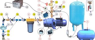
The structure of a single-stage centrifugal pump is shown in more detail in this figure:
Single stage pump diagram
| Frame |
| Working wheel |
| Drive shaft sealing mechanism |
| Shaft |
| Bearing chamber seal |
| Bearings |
| Support support |
| Eyelet for monitoring the oil level in the bearing chamber |
Principle of operation
The operation of this type of equipment is based on the principle of using centrifugal forces that are formed inside the pump housing during operation of the impeller. So:
An impeller sits on the mechanism shaft, secured by a strong keyed connection. Torque is transmitted from the impeller to the equipment shaft. A durable and elastic coupling is used to secure the pump shaft and the electric motor shaft.
- The centrifugal pump is equipped with one impeller, the blades of which have a concave shape. When the mechanism is brought into working position, the liquid enters the suction pipe. And then the electric motor drives the shaft, the movement of which causes the wheel to rotate.
- In turn, the wheel captures the liquid and pushes it away from the center of the wheel to the side. The working fluid gradually flows through the guide chamber into the discharge pipeline.
- In a short period of time, high pressure is formed between the pump blades, which pushes the liquid away, thereby freeing up space for a new portion of it to enter from the pipeline.
- The design of most models of single-stage household centrifugal pumps is equipped with a special modern filter located on the suction pipe.
The video in this article will introduce you in more detail to the operating technology of a single-stage centrifugal pump.
Equipment K 30 and K 30 30 – areas of application of pumps
The K 20 cantilever centrifugal pump is equipped with an axial supply in a horizontal position. It is used for pumping various liquids, while being located in a horizontal position. The K20 30 shaft is equipped with a single mechanical seal. Models with double gland seals can also be found on sale.
The K 30 30 pump is used in more areas. It is successfully used in industrial pumping stations, heating pipelines, urban and rural water supply. However, this equipment cannot be used in explosive atmospheres.
Among the technical characteristics of the pump of this modification, the following should be highlighted:
- Pressure to a depth of up to 30 m;
- Capacity – maximum 20 m
3/h. work;
- Rotation speed – 3 thousand rpm;
- Weight – 78 kg;
- Power – 4000 Watt.
The unit has high build quality, reliability and does not require constant maintenance.
Preparing for work
Unlike vibration pumps, which do not require filling the entire working chamber with a liquid medium to start operating, a centrifugal pump will not be able to start pumping “dry”. The air elasticity parameters are very different from the water parameters, and the rotor will simply spin idle, without creating the required vacuum. This will lead to overheating and premature wear of the device until it fails.
Pump filling schemes
This technical problem can be solved in various ways.
Filling water from a pipeline
The method is used for stationary water supply systems with a fixed location of pipelines. A constantly running water supply scheme is built in such a way that the centrifugal pump is at the lowest point, and there are always pipes filled with water above it in level. A check valve is installed on the suction pipeline to prevent water from flowing back into the well, borehole or container. Such a system must be filled with water only at the first start; all subsequent ones will take place in “wet” mode.
If the system is used occasionally or the check valve cannot be installed for some reason, other methods are used. The pump piping is installed in such a way that it is possible to supply water from the pipeline in the opposite direction until the working chamber and suction pipeline are filled. The air is released through a one-way air valve. As soon as the air whistling from it stops and water appears, it means the system is full and you can turn on the pump.
For filling from a high-pressure pipeline, a pressure-reducing ejector is used. Filling is also carried out until liquid appears.
Another method is used at large pumping stations with a high degree of automation. There, a vacuum pump is used to pump out air, and after the working chamber is filled and the water presence sensor is activated, the automation starts the installation.
Filling water from the tank
If there is no water in the pipeline, then it is poured from a reservoir equipped with a valve, temporarily or permanently connected to the outlet pipe. In stationary systems, the tank is permanently installed; before starting, the valve is opened and water fills the working chamber and supply pipeline. Start the pump. Having confirmed the successful launch by the even low sound of its operation, the valve is closed.
Scheme of filling the pump from the reservoir
Mobile systems, such as garden pumps or pumps for inflatable pool filtration systems, are filled from a bucket or watering can by unscrewing the coarse filter cap until air bubbles stop coming out and a mirror of water appears. Next, close the lid and start the device.
Pump K 30 - design features of the device
This unit has a horizontal design and is equipped with a closed wheel.
The single-stage device K45 30 is located on a common frame with an electric drive and is connected to each other via a coupling. The pump housing is made of cast iron. The rotor in the unit design rotates in bearing supports counterclockwise. There is an arrow on the device casing indicating the direction of movement of the rotor. The flow part of the device is also made of cast iron. In order to protect the shaft from leakage, manufacturers use an oil seal. As a result, the fluid loss from the pump is no more than 2 l/h. work.
These units are successfully used for pumping contaminated liquids; they have a simple design and high build quality.
Deep well pumps
The device of a deep well pump in all cases has a centrifugal operating principle. To increase the pressure and create a head of 20 atmospheres (200 m), a second pump is attached to the outlet of the first pump with an inlet. This principle of installing a deep-well pump in a well is called stages.
Deep well pumps according to technical characteristics are selected based on:
- source depth;
- the water supply power that the pump is capable of delivering;
- pressure;
source flow rate;
Positive sides:
- High efficiency and productivity.
- The dimensions of the device are compact, so it is not necessary to make a large-diameter well.
- Thanks to step technology, you can regulate the pressure of the water flow.
- Easy installation.
- For 10 years or more it does not require maintenance.
- Reliability of the design.
Negative sides:
- If the case is monolithic, then it will be impossible to repair the device.
- It is unacceptable to pump contaminated liquid.
Installation and repair of this type of equipment requires special knowledge and skills. It is much easier to choose a pump for a well over 20 meters after consulting with a specialist. It can be considered quite definitely that the price of a product is determined both by the complexity of its design and the depth of immersion.
The moment the deep pump is immersed in the well. It is determined by adding the water intake parameters of all devices in residential premises and outbuildings. Here you should add the water consumption for watering the garden.
For an average family of three people, a unit that supplies fifty liters of water per minute will be sufficient. For reliability, it is better to increase this value by ten percent.
The pressure of a submersible unit is determined by the height to which it is capable of raising the water column. There are special formulas for calculating this parameter, taking into account many factors. In a simplified way, the required pressure that a submersible unit must provide for a specific well is determined as follows.
Illustration of calculating the required pump pressure for a well
The number 30 is added to the depth of the well, expressed in meters. The resulting result increases by ten percent, the result will be the height of the water column that the submersible pump must provide. For example, if the well depth is twenty meters, then adding thirty and increasing the amount by ten percent, we get fifty-five meters. This is the pressure that the submersible pump should provide in this case.
Pumping equipment must always be in the water column, otherwise it will quickly fail due to overheating of the moving elements of its structure.
The technical passport of a well always indicates its characteristics, such as static and dynamic water levels, as well as the flow rate determined by the influx of liquid. The static level is established in the well after water has not been pumped out of it for some time. The height of the resulting water column balances the pressure of the aquifer, which is static, so the upper liquid level remains constant.
Illustration of the correct placement of a deep-well pump in a well These characteristics directly affect not only the required immersion depth of the pump, but also its parameters such as power and productivity. If the well was drilled with your own hands, there is, of course, no documentation of the aquifer. In this case, a simple practical method is suitable for determining the required immersion depth of the pump. It is as follows:
- a submersible pump attached to a cable is lowered to the bottom of the well;
- then it rises approximately two meters and turns on;
- if during a test run for an hour the water pressure and quality are good, this equipment position is suitable for operation;
- when liquid contaminated with silt and sand comes out, the pump rises fifty centimeters and the test is repeated;
- in the event of a sharp decrease in the pressure of the outgoing water, the pump immediately turns off and sinks deeper;
- in the optimal position found, the pump is fixed for continuous operation.
The diameter of the well should allow the pumping equipment to be raised and lowered freely; this must be taken into account when choosing it. The walls of the well are formed by a pipe. It is better to use pipes with a diameter of four inches, due to the fact that most modifications of submersible pumps are designed to use a pipe of this diameter, although three-inch pipes are sometimes used.
K50 160, K 80 50 200 and K80 65 160 – areas of application of the devices
The K 65 pump is used to pump clean water. Most of the elements of the device are made of SCh20 cast iron, and the shaft is made of steel. The pump design has special holes that drain fluid leaks through the seals. The role of the shaft seal is played by an oil seal with a special packing.
K 80 pumps are single-stage cantilever units with a horizontal design. They are used for pumping water with temperatures over 80 °C.
There are two types of such pumps on sale:
- Units with a single shaft seal are indicated by the inscription “C”;
- Pumps with double gland seals are marked “SD”.
Pumps of the first type can pump liquid with a temperature of no more than 80 °C. Equipment of the second type is used to work with liquids with temperatures of 105–140 °C. Thanks to this, K 80 units are able to provide stable operation with absolute inlet pressure. In this case, the leakage of liquid from them will not be more than 2 liters/hour.
Pumps K65 200 and K100 80 160 – design features of the units
K 100 pumps have an almost identical design. They are centrifugal devices operating on the principle of one-way supply of pumped liquid towards the wheel. In these devices, the motor and horizontal pump are located on the same platform.
The wheel of the unit K 100 65 200 is a closed type element. The pump is equipped with an axial liquid supply. Angular contact and radial ball bearings act as rotor support.
In the upper part of the housings of the units there are holes closed with a plug. When the holes are opened, air escapes from the pumps. The lower parts are equipped with holes for draining liquid.
The areas of application for K 100 pumps are quite extensive. The units can be used to pump clean and contaminated water and other liquids with a slightly higher density. Fecal devices have an additional protective coating on the body and main components.
How to choose a good pump?
To choose the right pump for your dacha or home, you must first clearly formulate the task it will perform.
For clean and drinking water.
To provide clean water at home or cottage, where it will be used for drinking, cooking, and performing hygiene procedures, you should prefer a vortex pump. It provides sufficient pressure, is durable (when pumping clean water) and unpretentious.
For watering and heating.
If a site needs a universal option that can provide site owners with both technical and drinking and irrigation water, then the choice should be made in favor of a centrifugal pump.
For sewage.
Pumping contaminated water clearly requires the installation of a vibration pump - drainage or fecal.
When installing the motor, carefully study its main characteristics. All of them must at least meet the performance and pressure parameters required from the device. Also make sure that your water source (especially if it is a well) is capable of renewing its supply at a rate faster than the pumping rate.