Manufactured industrial centrifugal cantilever pumps comply with the international standard ISO2858-75 “Centrifugal pumps with axial entry (nominal pressure 16.0 bar). Designation, nominal parameters and dimensions" regarding the design and parameters of cantilever pumps. Cantilever pumps are produced in two versions: - for water up to 80°C (with gland seal) - for water up to 105°C (with mechanical seal).
The permissible pressure at the pump inlet is 3.5 kgf/cm2 (can be used as a booster). The flow part is made of gray cast iron. The pumps are manufactured with a flow rate from 3 to 480 m3/h and a pressure from 3.5 to 125 m and are designed for pumping under stationary conditions water, except sea water, with a pH of 6 - 9, containing various mechanical impurities of no more than 0.10% by volume and particle size no more than 0.21 mm. The K-type pump is designed for operation in stationary conditions.
Cantilever centrifugal pumps for hot and cold water are produced with various options for turning the impeller (a, b, c). The direction of rotation is clockwise when viewed from the electric drive. The design of the pumps includes holes to drain water leaks through the stuffing box (face) seal.
Example of a pump unit symbol:
K80-50-200 a/4-5 UHL4
- K - pump type - cantilever pump, centrifugal
- 80 — diameter of the suction pipe, mm,
- 50 — diameter of the pressure pipe, mm,
- 200 - nominal diameter of the impeller, mm,
- a - first turning of the impeller,
- /4 - rotation speed 1450 rpm,
- -5 - with mechanical seal,
- UHL4 - climatic version and placement category.
Modern high-tech equipment is used in production, which allows us to produce high-quality pumps. Large production volume ensures low prices for pumps and pumping units.
Design Features
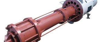
To pump water, centrifugal cantilever pumps of type K are most often used. Their impeller with blades is mounted on a shaft, the reverse end of which is located in a bearing assembly. A design feature that distinguishes K-type pumps is the presence of a special compensation chamber in them, which makes it possible to avoid leaks that can occur in cases where the value of the liquid pressure created by the pump exceeds standard values.
Protection against internal and external leaks through the device body is provided by the front and rear sealing elements that are equipped with each K-type pump. The design of such cantilever pumps also has a replaceable protective sleeve. Its use allows you to reduce wear on the shaft on which the impeller of the device is fixed.
Cantilever pump type K
Balancing the axial force created during the operation of cantilever pumps, whose power does not exceed 10 kW, is ensured by bearings. In devices of higher power, this problem is solved using special relief holes made in the impeller disk.
What is a cantilever pump?
A cantilever pump is a device whose function is to collect and pump clean or slightly contaminated water, which does not contain large solids. The maximum size of fractions present in the liquid should not exceed 0.2 mm, and the percentage of their content should not exceed 0.1%.
Units of this kind are used today in several areas:
- In irrigation and watering systems;
- In water supply structures;
- In public utilities;
- In chemical production.
Regardless of the application, cantilever pumps show excellent performance, high productivity and long service life.
Pumping equipment types K and KM
The main design elements of centrifugal cantilever pumps belonging to type K are:
- frame;
- bearing units;
- a shaft with an impeller attached to it;
- stuffing box elements;
- replaceable protective sleeve;
- support bracket.
Drawing of a cantilever pump
One of the varieties of pumping devices of this type are monoblock cantilever pumps, the designation of which contains the letters KM. Pumps of this series are characterized by high power, so they are used mainly in manufacturing enterprises and for equipping large utility networks. Powerful and productive pumps of the KM series are characterized by such disadvantages as:
- large dimensions and significant weight;
- low reliability of sealing units (this leads to the fact that inspection and maintenance of pumping devices of this type is required quite often);
- longer, more complex and expensive repairs compared to type K pumps;
- the complexity and inconvenience of replacing the electric motor if the need arises.
Cantilever pump type KM
The design of a cantilever pump - what does the device consist of?
Their design and the materials from which they are made depend on the areas of use of the units. Pumps used in industry are equipped with steel wheels, and in some cases with cast iron elements. Devices used in the chemical industry are equipped with drums made of various alloys that are resistant to aggressive substances.
The unit body is made of aluminum, stainless steel or cast iron. Oil seals, rings and cuffs are made from materials designed for the temperature of the pumped liquid.
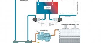
Operating principle
The principle by which a cantilever-type centrifugal pump operates is quite simple.
- When the power supply to the drive motor is turned on, the impeller equipped with blades begins to rotate.
- When passing through the area of the internal chamber where the inlet pipe of the pump is located, a vacuum of air is created in it, which facilitates the suction of the liquid medium through the pipe.
- The liquid entering the cantilever pump begins to move along with the impeller blades, which ultimately leads to an increase in the pressure of the pumped medium in the area of the discharge pipe and its pushing through it into the pipeline system.
When the impeller of a cantilever pump equipped with blades rotates, a centrifugal force is created, due to which the flow rate of the liquid pumped by such a device increases.
Operating principle of a cantilever pump
Meanwhile, it should be borne in mind: if a cantilever pump intended for equipping a water supply system is selected incorrectly, then too high a rotation speed of its impeller with blades can lead to the creation of insufficient air pressure in the inlet pipe, which will reduce the efficiency of the equipment. . When using a centrifugal cantilever pump, the impeller of which rotates at too high a speed, the pumped liquid medium in the working chamber transforms into steam, which then condenses. This leads to a phenomenon called cavitation. That is why you should have a good understanding of how to choose a cantilever pump to equip water supply systems with certain technical characteristics.
Sectional view of a cantilever chemical pump
Types of cantilever pumps - classification of market models
Console units can be of several types. Depending on the design, the following types of pumps are distinguished on the market:
- Type K equipment is a standard device, the design of which includes a horizontal housing, a drive and a wheel, which are interconnected by means of an elastic coupling;
- KM pumps - this class includes monoblock units. Each monoblock pump does not have a separate shaft of the working element in its design;
- Units of the KMP type are monoblock boosting devices manufactured for use in utility companies. They are almost no different from the previous type of pumps;
- Pumps of the KML group are cantilever-linear units, the impellers of which have vertical axes and a linear arrangement of inlet and outlet pipes.
The first type of units are in greatest demand. They are used in production, have excellent characteristics and have a long service life.
How to choose the right cantilever pump
In order for a cantilever pump used for pumping a liquid medium to be effective, it must be correctly selected based on the characteristics of the pipeline system for which it is planned to use such a device. For this purpose, they turn to special catalogs, which provide a list of pumps produced by modern industry, describe their design and provide the technical characteristics of the listed equipment. In addition, such catalogs contain drawings of pumping equipment, which indicate all the installation dimensions of these devices.
The selection of an electric pump model from the catalog is carried out at the stage of preliminary design of the water supply system. To more accurately select the model of a centrifugal cantilever pump to equip a specific pipeline, you should contact the manufacturers, from whom you can find out the technical characteristics of a particular device.
Example of marking of a cantilever pump
Let's consider the features of choosing a cantilever pump belonging to type K. First, the dimensions of the pump are selected, for which they are guided by the maximum fluid supply that such a device should provide. Before choosing a pump with the required characteristics, plot the relationship between pressure (Q) and its flow (H). A specific pump model is first selected according to its dimensions, and then a more precise selection of the device is carried out according to the schedule. Based on the required technical characteristics of the pump and the plotted schedule, a model with a certain impeller diameter is selected. It should be borne in mind that the pressure and flow curve of the selected pump must pass through the given point of the plotted graph or be above it.
The main requirement when choosing a cantilever-type pump is that the cavitation characteristics of such a device match the parameters of the pipeline system being created.
To check that the selected pump corresponds to the pipeline system according to the above parameter, it is necessary to calculate the cavitation reserve of such a system, for which the formula is used:
Δ h = ((Pa – Pt) / γ) – [± Ho] – Σ hbw, where:
Pa is the absolute pressure formed on the surface of the liquid in the tank from where it is pumped out;
Pt – saturated vapor pressure created when pumping a liquid medium at operating temperature;
γ – specific gravity of the pumped liquid medium, measured in N/m3;
Ho is the suction height, which is also called the geometric head of the pump (this parameter is defined as the distance between the axis of the pump shaft and the upper level of the liquid located in the pumped-out reservoir; it can have a positive value if the pump is located above the level of the pumped-out liquid medium, and negative if below);
Σ hbw is the total pressure loss of the pumped liquid that occurs in the suction pipeline when the pump operates at maximum flow.
The most important parameter of the selected cantilever pump is the power of the electric motor.
This parameter is determined by calculation, for which the formula is used:
Ne = RN γ/1000, where:
R is the safety factor;
N – pump power, measured in kW, which it has at nominal operating mode;
γ is the specific gravity of the liquid for which the pump is used.
Having calculated the above parameters, plotted a graph of the dependence of the pressure of the pumping device and the value of its supply, you can select a model of a cantilever pump, the technical characteristics of which will optimally correspond to the level of the tasks that are to be solved with its help.
Technical characteristics of pumps K (click to enlarge)
SYMBOL
For example 1K 80-50-200a-t-E U3.1 TU 3631-096-05747979-97 , where:
- 1 – pump modernization index;
- K – console pump;
- 80 – diameter of the inlet pipe, mm;
- 50 – diameter of the outlet pipe, mm;
- 200 –diameter of the impeller (nominal), mm;
- a is the impeller turning index:
- a, b, c - reduced diameter of the impeller,
- l, m - increased diameter of the impeller
- c — stuffing box seal,
- t- mechanical seal
For example K45/30 U3.1 TU3631-226-05747979-2003 , where:
- K - console
- 45 — flow, m³/h
- 30 — head, m
- U3.1 - climatic version
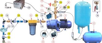
Correct installation
For console pumps to effectively cope with the tasks assigned to them, they need to be installed correctly. In this case, you should adhere to the following recommendations.
- To install the pump, you should use a level and high-quality concrete base that can ensure reliable fastening of such a device. A concrete foundation pad, the mass of which must exceed the mass of the pump itself by at least one and a half times, is necessary in order to absorb vibrations, shock loads and linear deformations that occur during operation of the equipment. The width and length of the foundation pad for the pump are calculated so that they protrude beyond the perimeter of the supporting frame of the equipment by at least one meter. After preparing the concrete base, the pump is installed in its central part and securely fixed.
- When connecting pipeline elements to the pumping unit, it should be taken into account that significant mechanical loads are not transferred to the equipment body.
- The diameters of the pressure and suction pipes must be selected taking into account the pressure that the pumping unit will create.
- When installing pipes (especially the suction line), care should be taken to ensure that there is no accumulation of air in them.
- When installing it, shut-off valves or taps must be installed on both sides of the cantilever pump, which are necessary to prevent fluid from leaking out of the system during maintenance or repair of the pumping unit.
- Both the suction and pressure pipelines approaching the pump must have reliable fastenings, and they should be located as close as possible to the installation body.
- The connection of the suction and pressure lines of the pipeline to the pump is carried out using counter flanges, which are attached to the flanges of the device in such a way as to remove all stress arising in the system from it.
- In order for a cantilever-type pumping unit to operate efficiently and without failures, it is necessary to minimize the vibrations and noise that arise during its operation, which is achieved in various ways. This requirement is especially relevant if the power of the drive motor of the cantilever pump exceeds 11 kW. Meanwhile, it should be borne in mind that lower-power drive motors can also create unwanted vibration loads and noise during operation.
When installing cantilever pumps, the overall dimensions and location of the pipes are taken into account
Vibrations and noise during the operation of a cantilever-type centrifugal pump can be caused by a rotating rotor and a running engine, as well as by a liquid flow moving through internal lines. To reduce the level of such vibrations, which negatively affect not only the technical condition of the equipment itself, but also the condition of the building in which it is installed, vibration inserts and vibration supports are traditionally used.
The most effective means of vibration damping are vibration inserts and vibration mounts
The main purpose of vibration supports, which are necessarily used when installing pumping equipment, is to prevent the transfer of vibration loads that occur during its operation to the building structures. When choosing the material of manufacture and design of such supports, the strength of vibration created by the pumping unit, as well as the rotational speed of the electric motor shaft with which such an installation is equipped, are taken into account.
Vibration inserts for electric pumps are used to prevent vibrations in the pipeline system served by pumping equipment. Elements such as vibration inserts compensate for the compression and expansion loads that occur in pipelines under the influence of changes in the temperature of the liquid transported through them, and also reduce the mechanical stresses created in such systems under the influence of pressure surges of the liquid moving through them.
Technical characteristics of pumps K
| Unit brand | Feed, cubic m/h | Head, m | Working area, m/h | Electric motor brand | Electric motor characteristics | Overall dimensions of the unit, mm | Diameter of pipes, mm | Unit weight, kg | ||||
| kW | rpm | L | B | H | entrance | exit | ||||||
| K 50-32-125 | 12,5 | 20 | 9…18 | AIR 80V2 | 2,2 | 3000 | 800 | 368 | 312 | 50 | 32 | 80 |
| K 8/18 | 12,5 | 20 | 6…14 | AIR 80V2 | 2,2 | 3000 | 790 | 312 | 330 | 50 | 32 | 62 |
| K 50-32-125a | 10 | 16 | 8…16 | AIR 80A2 | 1,5 | 3000 | 800 | 368 | 312 | 50 | 32 | 77 |
| K 8/18a | 8 | 18 | 4…12,5 | AIR 80A2 | 1,5 | 3000 | 790 | 312 | 330 | 50 | 32 | 61 |
| K 65-50-125 | 25 | 20 | 18…35 | AIR 90L2(80В2) | 3,0(2,2) ² | 3000 | 811 | 368 | 325 | 65 | 50 | 100 |
| By 20/18 | 20 | 18 | 17…23 | AIR 80V2 | 2,2 | 3000 | 795 | 215 | 342 | 65 | 50 | 62 |
| K 65-50-160 | 25 | 32 | 18…35 | AIR 100L2 | 5,5 | 3000 | 865 | 397 | 352 | 65 | 50 | 110 |
| By 20/30 | 25 | 32 | 12…31 | AIR 100L2 | 5,5 | 3000 | 865 | 300 | 343 | 65 | 50(40) 3 | 84 |
| K 65-50-160a | 20 | 30 | 15…32 | AIR 100S2 | 4,0 | 3000 | 845 | 397 | 352 | 65 | 50 | 104 |
| By 20/30 | 20 | 30 | 10…29 | AIR 100S2 | 4,0 | 3000 | 835 | 300 | 343 | 65 | 50(40) 3 | 77 |
| K 20/30a | 20 | 25 | 9…22 | AIR 90L2 | 3,0 | 3000 | 810 | 290 | 343 | 65 | 50(40) 3 | 67 |
| K 20/30b | 15 | 20 | 8,5…20,5 | AIR 80V2 | 2,2 | 3000 | 810 | 275 | 353 | 65 | 40 | 61 |
| K 80-65-160 | 50 | 32 | 37…63 | AIR 112M2 | 7,5 | 3000 | 925 | 427 | 400 | 80 | 65 | 145 |
| K 45/30 | 45 | 30 | 24…52 | AIR 112M2 | 7,5 | 3000 | 1065 | 300 | 425 | 80 | 65(50) 3 | 145 |
| K 80-65-160a | 45 | 28 | 35…56 | AIR 100L2 | 5,5 | 3000 | 812 | 427 | 400 | 80 | 65 | 125 |
| K 45/30a | 35 | 23 | 22…42 | AIR 100L2 | 5,5 | 3000 | 975 | 300 | 405 | 80 | 65(50) 3 | 120 |
| K 80-50-200 | 50 | 50 | 35…70 | AIR 160S2 | 15,0 | 3000 | 1120 | 458 | 455 | 80 | 50 | 235 |
| K 45/55 | 45 | 55 | 32…60 | AIR 160S2 | 15,0 | 3000 | 1300 | 393 | 494 | 80 | 50 | 220 |
| K 80-50-200a | 45 | 40 | 30…55 | AIR 132M2 | 11,0 | 3000 | 990 | 428 | 430 | 80 | 50 | 185 |
| K 45/55a | 40 | 41,5 | 27…52 | AIR 132M2 | 11,0 | 3000 | 1120 | 370 | 448 | 80 | 50 | 160 |
| K 90/20 | 90 | 20 | 60…100 | AIR 112M2 | 7,5 | 3000 | 1055 | 332 | 412 | 100 | 80 | 155 |
| K 90/20a | 72 | 18 | 50…80 | AIR 100L2 | 5,5 | 3000 | 1010 | 332 | 388 | 100 | 80 | 136 |
| K 100-80-160 | 100 | 32 | 70…130 | AIR 160S2 | 15,0 | 3000 | 1235 | 458 | 455 | 100 | 80 | 265 |
| K 90/35 | 90 | 35 | 65…115 | AIR 160S2 | 15,0 | 3000 | 1290 | 393 | 494 | 100 | 80 | 225 |
| K 100-80-160a | 90 | 26 | 60…120 | AIR 132M2 | 11,0 | 3000 | 1105 | 458 | 430 | 100 | 80 | 205 |
| K 90/35a | 85 | 29 | 60…110 | AIR 132M2 | 11,0 | 3000 | 1110 | 370 | 438 | 100 | 80 | 162 |
| K 100-65-200 | 100 | 50 | 70…130 | AIR 180M(S)2 | 30(22) ² | 3000 | 1290 | 498 | 510 | 100 | 65 | 340 |
| K 100-65-200a | 90 | 40 | 60…120 | AIR 160M2 | 18,5 | 3000 | 1265 | 498 | 475 | 100 | 65 | 275 |
| K 100-65-250 | 100 | 80 | 70…130 | AIR 200L2 | 45,0 | 3000 | 1390 | 568 | 605 | 100 | 65 | 460 |
| K 100-65-250a | 90 | 67 | 60…120 | AIR 200M2 | 37,0 | 3000 | 1345 | 568 | 605 | 100 | 65 | 435 |
| K 150-125-250 | 200 | 20 | 120…240 | AIR 160M(S)4 | 18,5(15) ² | 1500 | 1335 | 475 | 675 | 150 | 125 | 370 |
| K 150-125-250a | 180 | 16 | 100…220 | AIR 132M4 | 11,0 | 1500 | 1175 | 445 | 598 | 150 | 125 | 305 |
| K 150-125-315 | 200 | 32 | 120…240 | AIR 180M4 | 30,0 | 1500 | 1375 | 540 | 705 | 150 | 125 | 450 |
| K 160/30 | 160 | 30 | 124…194 | AIR 180M4 | 30,0 | 1500 | 1515 | 515 | 555 | 150 | 100 | 435 |
| K 150-125-315a | 180 | 26 | 100…200 | AIR 180S4 | 22,0 | 1500 | 1325 | 540 | 705 | 150 | 125 | 430 |
| K 160/30a | 140 | 29 | 118…184 | AIR 180S4 | 22,0 | 1500 | 1495 | 515 | 555 | 150 | 100 | 410 |
| K 200-150-250 | 315 | 20 | 220…380 | AIR 180M4 | 30,0 | 1500 | 1375 | 540 | 725 | 200 | 150 | 460 |
| K 200-150-250a | 290 | 16 | 200…340 | AIR 180S4 | 22,0 | 1500 | 1325 | 540 | 725 | 200 | 150 | 440 |
| K 200-150-315 | 315 | 32 | 220…380 | AIR 200L(M)4 | 45 (37) ² | 1500 | 1665 | 600 | 785 | 200 | 150 | 645 |
| K 290/30 | 290 | 30 | 220…330 | AIR 200L(M)4 | 45 (37) ² | 1500 | 1645 | 585 | 630 | 200 | 125 | 550 |
| K 200-150-315a | 290 | 26 | 180…340 | AIR 180M4 | 30,0 | 1500 | 1535 | 600 | 730 | 200 | 150 | 560 |
| K 290/30a | 250 | 24 | 194…300 | AIR 180M4 | 30,0 | 1500 | 1555 | 585 | 585 | 200 | 125 | 460 |
| K 200-150-400 | 400 | 50 | 220…460 | AIR 250M4 | 90,0 | 1500 | 1790 | 795 | 885 | 200 | 150 | 1005 |
| K 200-150-400a | 400 | 40 | 220…460 | AIR 250S4 | 75,0 | 1500 | 1750 | 795 | 885 | 200 | 150 | 960 |
Equipment K 20 30 and K 30 30 – areas of application of pumps
The K 20 cantilever centrifugal pump is equipped with an axial supply in a horizontal position. It is used for pumping various liquids, while being located in a horizontal position. The K20 30 shaft is equipped with a single mechanical seal. Models with double gland seals can also be found on sale.
The K 30 30 pump is used in more areas. It is successfully used in industrial pumping stations, heating pipelines, urban and rural water supply. However, this equipment cannot be used in explosive atmospheres.
Among the technical characteristics of the pump of this modification, the following should be highlighted:
- Pressure to a depth of up to 30 m;
- Productivity – maximum 20 m3/h. work;
- Rotation speed – 3 thousand rpm;
- Weight – 78 kg;
- Power – 4000 Watt.
The unit has high build quality, reliability and does not require constant maintenance.
K65 50 160, K 80 50 200 and K80 65 160 – areas of application of the devices
The K 65 pump is used to pump clean water. Most of the elements of the device are made of SCh20 cast iron, and the shaft is made of steel. The pump design has special holes that drain fluid leaks through the seals. The role of the shaft seal is played by an oil seal with a special packing.
K 80 pumps are single-stage cantilever units with a horizontal design. They are used for pumping water with temperatures over 80 °C.
There are two types of such pumps on sale:
- Units with a single shaft seal are indicated by the inscription “C”;
- Pumps with double gland seals are marked “SD”.
Pumps of the first type can pump liquid with a temperature of no more than 80 °C. Equipment of the second type is used to work with liquids with temperatures of 105–140 °C. Thanks to this, K 80 units are able to provide stable operation with absolute inlet pressure. In this case, the leakage of liquid from them will not be more than 2 liters/hour.
Pumps K100 65 200 and K100 80 160 – design features of the units
K 100 pumps have an almost identical design. They are centrifugal devices operating on the principle of one-way supply of pumped liquid towards the wheel. In these devices, the motor and horizontal pump are located on the same platform.
The wheel of the unit K 100 65 200 is a closed type element. The pump is equipped with an axial liquid supply. Angular contact and radial ball bearings act as rotor support.
In the upper part of the housings of the units there are holes closed with a plug. When the holes are opened, air escapes from the pumps. The lower parts are equipped with holes for draining liquid.
The areas of application for K 100 pumps are quite extensive. The units can be used to pump clean and contaminated water and other liquids with a slightly higher density. Fecal devices have an additional protective coating on the body and main components.
Pump K 45 30 – design features of the device
This unit has a horizontal design and is equipped with a closed wheel. The single-stage device K45 30 is located on a common frame with an electric drive and is connected to each other via a coupling.
The pump housing is made of cast iron. The rotor in the unit design rotates in bearing supports counterclockwise. There is an arrow on the device casing indicating the direction of movement of the rotor. The flow part of the device is also made of cast iron. In order to protect the shaft from leakage, manufacturers use an oil seal. As a result, the fluid loss from the pump is no more than 2 l/h. work.
These units are successfully used for pumping contaminated liquids; they have a simple design and high build quality.