A unit designed for welding products is considered to be a semi-automatic welding machine. Such devices can come in various types and shapes. But the most important thing is the inverter mechanism. It is necessary that it be of high quality, multifunctional and safe for the consumer. Most professional welders do not trust Chinese products and make the devices themselves. The manufacturing scheme for homemade inverters is quite simple. It is important to consider for what purposes the device will be manufactured.
There are inverters for:
- Welding using flux-cored wire;
- Welding with various gases;
- Welding under a thick layer of flux;
Sometimes, to achieve a high-quality result and obtain an even weld, the interaction of two devices is necessary.
Inverter devices are also divided into:
- Single-hull;
- Double-hull;
- Pushing;
- Pulling;
- Stationary;
- Mobile, which includes a trolley;
- Portable;
- Designed for beginner welders;
- Designed for semi-professional welders;
- Designed for professional craftsmen;
Inverter circuit:
What will you need?
A homemade device, the circuit of which is very simple, includes several main elements:
- A mechanism with the main function responsible for controlling the welding current;
- Mains power supply;
- Special burners;
- Convenient clamps;
- Sleeves;
- Cart;
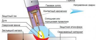
Scheme of welding using a semi-automatic device in a protective gas environment:
The master will also need:
- A mechanism that provides wire feeding;
- A flexible hose through which wire or powder will be supplied to the weld under pressure;
- Bobbin with wire;
- Special control device;
Rework algorithm
The vast majority of components are used without significant modifications. Re-equipment will be required for the filler material feeder, since the feed rate of the filler through the flexible hose must match the melting rate of the filler metal. It is necessary to take into account the adjustment option in the mechanism, because the speed varies based on the type of metal being welded, the type and cross-section of the filler material.
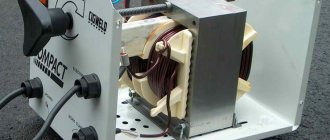
In a working inverter, first of all, the transformer device included in its structure should be rearranged. It is covered with an additional layer consisting of a copper strip and paper with a heat-sensitive coating.
Do not use ordinary copper wire for the transformer device. During the welding cycle, it heats up too much and can stall the operation of the entire semi-automatic welding unit.
The secondary winding of the transformer device also requires improvement. It is covered in 3 layers of thin sheet steel, insulated with fluoroplastic tape. The ends of the wound winding are connected by soldering. After performing these steps, electrical conductivity increases significantly.
An important component is the fan, which will cool the unit, protecting it from excessive heating.
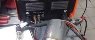
A current converter for manual electric welding very easily becomes a power source for a semi-automatic unit. The working device can not be disassembled, and all auxiliary equipment can be located in another building. It contains a reel with filler material, which rotates freely on the drum, and a feeding device. On the side of the casing there is a speed converter for the filler material and a connector for connecting the guide hose.
A used PC system case will easily do. It will turn out neat and concise.
The parameters of the electric current can be adjusted on the inverter, therefore, the “positive” terminal is connected to the part from it.
“Minus” is removed from the inverter and inserted into a new supporting shell. Here it is connected to the terminal of the supply hose. The main thing is that the filler material is connected to this potential.
The hose for supplying the protective gas mixture, which runs from the cylinder to the burner gun, is also fixed in the housing. If you use the valve from the car's windshield wipers, the gas mixture supply setting will appear.
The presented assembly is simple to implement, and the inverter can be used in parallel for manual electric arc welding and as a power source for a welding unit made at home, operating in a semi-automatic mode.
Principle of operation
The operating principle of the inverter includes:
- Adjusting and moving the burner;
- Control and monitoring of the welding process;
When the unit is connected to the electrical network, a conversion of alternating current to direct current is observed. For this procedure you will need an electronic module, special rectifiers and a high-frequency transformer. For high-quality welding, it is necessary that the future unit has parameters such as the feed speed of the special wire, current strength and voltage in identical balance. For these characteristics, you will need an arc power source that has current-voltage readings. The length of the arc must be determined by the specified voltage. The wire feed speed directly depends on the welding current.
Homemade device diagram:
The electrical circuit of the device provides for the fact that the type of welding greatly influences the progressive performance of the devices as a whole.
Electrical diagram of a homemade device:
DIY semi-automatic - detailed video
Semi-automatic welding from an inverter
To convert an inverter into a semi-automatic welding machine, you will need three main modules. Electric, providing current from the inverter and welding mode, a mechanism for supplying wire and a torch with a nozzle. The burner creates a gaseous environment in the form of a cloud of protective inert gas that prevents oxidation of the molten metal. For this, a carbon dioxide cylinder is used, which is connected to the device using a hose and an inlet fitting. If you use filler material with a special coating that forms a protective environment, you can do without a cylinder. This method is common among craftsmen.
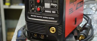
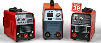
Figure 2 - Semi-automatic inverter
The torch replaces the electrode holder familiar to welders. Externally, it looks like a pistol grip with a key that provides wire feeding.
It moves along a thin channel passing inside the rubberized sleeve connecting the semiautomatic device to the burner. The channel for supplying gas during welding is located in the same sleeve and ends with a nozzle at the end of the torch.
For high-quality welding, a semi-automatic inverter must maintain a constant voltage at the output, like factory equipment.
Required tools and materials
To create a semi-automatic machine from an inverter with your own hands, you will need to prepare the necessary components and equipment.
List of tools and materials:
- Inverter with output current from 150 A.
- A wire feed mechanism that moves it without jerking or slowing down.
- Gas burner for melting the bath.
- A supply hose that will serve as a guide sleeve for the wire moving towards the work area.
- A gas hose that supplies protective carbon dioxide to the welding site.
- Spool of filler wire.
- Electronics unit for controlling the operation of a semi-automatic welding machine. Here the current strength, voltage and operating speed are adjusted.
- Semi-automatic welding circuit diagram.
Figure 3 - Diagram of a semi-automatic welding machine
Most of the components are used without significant changes. The wire feed mechanism will require modifications so that the process matches the melting speed. The device must be adjustable, because the speed varies depending on the type of materials being welded, the type and diameter of the wire.
Inverter conversion process
In a finished inverter, you first need to remake the transformer included in it. It is covered with an additional layer consisting of copper strip and thermal paper.
Ordinary copper wire cannot be used for a welding transformer. When welding, it overheats greatly and can stop the operation of the entire semi-automatic welding machine.
The secondary winding of the transformer will also require intervention. It is covered in three layers of tin, insulated with fluoroplastic tape. The ends of the applied winding are soldered. As a result of manipulation, the conductivity increases significantly.
An important element is a fan that will cool the device, protecting it from overheating.
Figure 4 - Inverter winding
An inverter for manual welding can easily be converted into a power source for a semi-automatic machine. A functioning device does not need to be disassembled, but all additional equipment is placed in a separate housing. It houses a freely rotating spool of welding wire and a pulling mechanism. The side panel displays a wire speed regulator and a socket for connecting a hose.
An old computer system case will do just fine. It turns out compact and neat.
The current parameters can be adjusted on the inverter, then the “positive” terminal is connected to the workpiece from it.
The “negative” contact is removed from the inverter and goes into the new housing. Here it is connected to the sleeve terminal. It is important that the welding wire is connected to this potential.
The gas hose running from the cylinder to the burner is also attached to the housing. If you use the valve from a car windshield wiper, the gas supply will be adjusted.
The above arrangement is simple to implement, and the inverter can be simultaneously used for manual arc welding and as a power source for a home-made semi-automatic machine.
Wire feeder assembly
The feed mechanism is necessary for the uniform flow of electrode wire at the required speed into the welding zone.
Consumables are selected based on the type of metal and the purpose of welding work. Material and size may vary. Therefore, the device must be adjustable to suit different types of wire and welding conditions. Running wire diameters: 0.8; 1; 1.2 and 1.6 mm.
The wire drawing mechanism is purchased ready-made in the electrical goods department or made from improvised materials. For assembly you will need a motor from car windshield wipers, three bearings, a pressure spring and a roller mounted on the electric motor shaft. And also plates at least 1 cm thick of a suitable size on which the bearings are mounted.
Figure 5 — Diagram of the electric motor speed controller
The components are placed on a textolite plate with a thickness of at least 5 mm. The wire is inserted between the bearing and the roller. The exit location should coincide with the fastening of the end of the supply hose into which it is pulled. The wire is wound evenly and carefully onto the reel, because the quality of the future connecting seam depends on this. The coil is installed on a homemade support and fixed. During operation, the wire will unwind and flow to the joint to be welded. With the help of the feeding mechanism, it is possible to simplify and speed up welding work and make it more productive.
Figure 6 — Feeding mechanism
Burner assembly design
A welding torch is a welder’s working tool for making a weld in a protective gas environment.
It lasts no more than six months and is considered a consumable item. The burners operate on the same principle, although they differ in size, materials, maximum temperature, power and gas supply mechanism.
Structural elements:
- base with handle;
- nozzle;
- holder;
- tip;
- insulating sleeve.
Figure 7 — Burner assembly design
Welding is accompanied by overheating of the torch elements. The nozzle and current carrying tip suffer the most. The duration of operation will depend on the material of the tip. Copper is widely used, and in more expensive versions, tungsten. The average tip life is 200 hours. They are made quick-change because they have to be changed frequently.
The handle is made of heat-resistant insulating material, which reliably protects the welder from electric shock. On the torch handle, a button controls the on and off supply of consumables and protective gas. A feeding sleeve with a standard length of 2.5–7 m extends from the handle. The choice of sleeve length depends on the type of work performed.
It is not recommended to allow excess sleeves folded into rings. The output coil voltage causes them to become very hot, which can cause a short circuit.
Figure 8 — Gas burner design
There is a wide selection of gas burners on the market. The models are characterized by the following parameters:
- load current;
- cooling method: air or water;
- the length of the sleeve;
- connection with a plug or Euro connector;
- control method: universal, push-button or valve.
The burner should be compact and lightweight. For a homemade device, a plug connector is sufficient. The plastic case must be durable and ergonomic. The burner is selected according to current parameters that are lower than those of a semiautomatic device.
To ignite the arc, it is necessary that the wire extends beyond the edge of the burner by 10–15 cm.
The supply of consumables is turned on by pressing a button on the torch, which is in the hands of the welder. The toggle switch on the body opens and closes the gas supply to the welding zone.
Control and Power
The semi-automatic device is controlled by a microcontroller.
It is also responsible for converting and stabilizing current. The power supply to the wire pulling mechanism and the valve that turns off the gas is supplied with a voltage of 12 V. To do this, you will need to install a small transformer with a rectifier. Switching between the motor and the valve occurs through a 12 V intermediate auto relay.
Assembly of the unit
The assembly instructions will help you make a quality semi-automatic welding machine. The work is carried out in the following sequence:
- Connect the inverter to power and control devices.
- Thread the wire into the feed mechanism and check for smooth movement.
- Set the required wire feed speed.
- Connect the burner to a hose, which is connected to the feeder.
- Connect a gas cylinder with a reducer and a pressure gauge to the burner.
- Turn on the inverter and feeder.
- Check the flow of gas and wire. After gas supply, the delay in wire movement should be 1–2 s. It enters a ready-made protective environment, otherwise it will stick.
When preparing a home-made semi-automatic machine for the first start-up, you need to take care of cooling the assembled semi-automatic welding machine so that it does not overheat. For this purpose, input and output rectifiers and power switches are mounted on radiators. On the inverter body where the radiator is located, that is, in the most heated zone, it is recommended to install a temperature sensor that will de-energize the device if it overheats.
After this, connect the power part to the control unit, and then turn on the semi-automatic device to the power supply. When the mains lights come on, the inverter needs to be tested. At the output of the device, a current is measured, which should not exceed 120 A. If its value is less, this means that a voltage below 100 V is supplied to the equipment through the wires. In this case, the current is changed and the voltage is controlled, achieving the desired parameters. In this case, the inverter should not overheat.
Under load, the semi-automatic device is checked as follows. The welding wires are connected to a rheostat designed for a current of 60 A and a resistance of at least 0.5 Ohm. The current supplied to the burner is controlled with an ammeter. If the current strength differs from the norm, change the resistance value.
After turning on the assembled semi-automatic device, the indicator should show a current strength of 120 A. This figure confirms the correctness of the work. If eights are displayed, then the reason is insufficient voltage in the supply wires. Welding inverters operate in the operating current adjustment range of 20–160 A.
Control during work
The performance and service life of the semi-automatic device depends on compliance with the temperature regime. The normal temperature on radiators is 75 °C. When overheating, breakdown or short circuit occurs, a sound signal appears. The electronic control unit will automatically reduce the operating current to 20 A, the sound signal will remain until the situation stabilizes. An error in the system is accompanied by the Err code on the indicator.
Created plan
Any scheme of a homemade device provides a separate sequence of operation:
- At the initial level, it is necessary to ensure preparatory purging of the system. It will accept the subsequent supply of gas;
- The arc power source must then be started;
- Feed wire;
- Only after all actions have been completed will the inverter begin to move at the specified speed.
- At the final stage, the seam should be protected and the crater welded;
Assembly of a rectifier based on a diode bridge
Diode bridge circuit
The manufacture of a homemade semi-automatic device powered by a household AC network requires the installation of a diode bridge. Equipping a single-phase transformer with a secondary voltage rectification device graphically looks like a symmetrical transfer of the lower sinusoids relative to the abscissa axis to the upper quadrants of the coordinate system.
After the rectifying device, the voltage ripple reaches 100 Hz. Twice during a period, an uncontrolled voltage drop from maximum to zero is not capable of maintaining stable combustion and ignition of the welding arc. This flaw is eliminated by a filter, a device designed to smooth out surges in voltage ripple.
Preparing the transformer
Your attention must be paid to the feeding mechanism. Using this device, the electrode wire must be fed. Due to the fact that this mechanism breaks down most often, high-quality calculations should be made. It is important to note that an increase in current in most cases leads to fire of the electrode. This causes severe damage to the product. But if the current is very weak, then it will not be possible to make a full-fledged unit. The resulting weld will be unreliable. Therefore, at this stage of preparation it is necessary to correctly perform all calculations.
How does a semi-automatic welding machine work?
The homemade device operates on the same principle as standard equipment. However, instead of electrodes, filler wire is used here. It is fed into the weld pool automatically using a special device. Due to the continuous operation of the mechanism, a melting zone is formed, allowing you to quickly connect 2 elements.
A transformer or inverter is included in the electrical circuit of a homemade semiautomatic device as a current source. An electric arc is formed on a pistol-type torch. The filler wire is fed through a rubberized hose. At the same time, gas flows through the channel.
The operating principle of a homemade welding machine is simple and the performance is high. The seam has a uniform surface and is characterized by increased strength. A homemade device is used for welding low-carbon steel and non-ferrous metals.
Power supply
Repair or fabrication of a structure includes a power source. Such a device can be a rectifier, inverter or transformer. It is this part that affects the volume and cost of the welder. Inverter power supplies are considered to be the most professional and high-quality devices.
Power supply diagram:
Semi-automatic Sanych
To make the transformer, Sanych used 4 cores from TS-720. The primary winding was wound with copper wire Ø 1.2 mm (number of turns 180+25+25+25+25), for the secondary winding I used an 8 mm2 busbar (number of turns 35+35). The rectifier was assembled using a full-wave circuit. For the switch I chose a paired biscuit. I installed the diodes on the radiator so that they would not overheat during operation. The capacitor was placed in a device with a capacity of 30,000 microfarads. The filter choke was made on a core from TS-180. The power part is put into operation using a TKD511-DOD contactor. The power transformer is installed TS-40, rewound to a voltage of 15V. The roller of the broaching mechanism in this semi-automatic machine has a Ø 26 mm. It has a guide groove 1 mm deep and 0.5 mm wide. The regulator circuit operates at a voltage of 6V. It is sufficient to ensure optimal feeding of the welding wire.
How other craftsmen improved it, you can read messages on various forums dedicated to this issue and delve into the nuances of manufacturing.
Control board
To create an inverter, a special control board is required. This device must have the following components installed:
- A master oscillator including a galvanic isolation transformer;
- The node with which the relay is controlled;
- Feedback blocks responsible for mains voltage and supply current;
- Thermal protection block;
- Antistick block;
Control unit printed circuit board:
Inverter setup
How to make an antenna for digital TV with your own hands
To ensure high-quality operation of a semiautomatic device with small dimensions, it is best to use toroidal type transformers. They have the highest efficiency.
The transformer for operation of the inverter is prepared as follows: it must be wrapped with a copper strip (40 mm wide, 30 mm thick), protected with thermal paper, of the required length. The secondary winding is made of 3 layers of sheet metal, insulated from each other. To do this, you can use fluoroplastic tape. The ends of the secondary winding at the output must be soldered. In order for such a transformer to operate smoothly and not overheat, it is necessary to install a fan.
Transformer winding diagram
Work on setting up the inverter begins with de-energizing the power section. Rectifiers (input and output) and power switches must have radiators for cooling. Where the radiator is located, which heats up the most during operation, it is necessary to provide a temperature sensor (its readings during operation should not exceed 75 0C). After these changes, the power section is connected to the control unit. When switched on. The network indicator should light up. You need to check the pulses using an oscilloscope. They should be rectangular.
Their repetition rate must be in the range of 40 ÷ 50 kHz, and they must have a time interval of 1.5 μs (the time is adjusted by changing the input voltage). The indicator should show at least 120A. It would not be superfluous to check the device under load. This is done by inserting a 0.5 ohm load rheostat into the welding leads. It must withstand a current of 60A. This is checked using a voltmeter.
A properly assembled inverter when performing welding work makes it possible to regulate the current in a wide range: from 20 to 160A, and the choice of operating current depends on the metal that needs to be welded.
To make an inverter with your own hands, you can take a computer unit, which must be in working condition. The body needs to be strengthened by adding stiffeners. An electronic part is mounted in it, made according to Sanych’s scheme.
Repair/modification of electrode wire feed speed device
Inverters are considered reliable devices. But if care is not taken care of, the devices may fail. The devices may require repairs. In most cases, the main cause is a broken regulator. When the first problems occur, the breakdown affects the further operation of the device. Therefore, in order to avoid future repairs, you should devote as much time as possible to high-quality assembly of the device.
The unit diagram includes a pressure roller. It is equipped with a special wire pressure level regulator. The unit also contains a wire feed roller, which has two small recesses. The welding wire should come out of them. The use of wire with a diameter of up to 1 mm is allowed. Immediately after the regulator there is a solenoid that controls the gas supply.
The regulator is considered a large element. It is secured with small bolts. Therefore, the fastening is extremely unreliable. The unit may warp, which may lead to malfunction. It is because of this reason that the device often breaks down and requires additional repairs.
Implementation of the electrical part
For this you will need:
- two automotive relays;
- diode;
- PWM regulator for the engine;
- capacitor with transistor;
- idle solenoid valve - for supplying gas to the burner. Any VAZ model will do, for example from a V8;
- wires.
The wire and gas supply control circuit is quite simple and is implemented as follows:
- when you press the button on the burner, relay No. 1 and relay No. 2 are activated;
- relay No. 1 turns on the gas supply valve;
- relay No. 2 works in tandem with a capacitor and turns on the wire feed with a delay;
- wire pulling is done with an additional button, bypassing the gas supply relay;
- To remove self-induction from the solenoid valve, a diode is connected to it.
- It is necessary to provide for connecting the burner to the power cable from the inverter. To do this, next to the Euro connector, you can install a quick-release connector and connect it to the burner.
The semi-automatic device has the following operating sequence:
- The gas supply is turned on.
- The wire feed starts with a slight delay.
This sequence is necessary so that the wire immediately enters the protective environment. If you make a semi-automatic machine without delay, the wire will stick. To implement it, you will need a capacitor and a transistor through which the motor control relay is connected. Operating principle:
- voltage is applied to the capacitor;
- it is charging;
- current is supplied to the transistor;
- the relay turns on.
The capacitance of the capacitor must be selected so that the delay is approximately 0.5 seconds - this is enough to fill the weld pool.
After assembly, the mechanism must be tested, and the manufacturing process can be seen on video.
DIY choke
In order to make a choke, you will need a transformer, an enamel wire with a diameter of more than 1.5 mm. Insulation is wound between the layers. Using an aluminum bus with dimensions of at least 2.5x4.5 mm, 24 turns are wound. The remaining ends of the bus remain 30 cm each. The core is laid using pieces of textolite with a gap of at least 1 mm. It is also allowed to wind the inductor on iron from an old tube color TV. But such a device can only have one coil. Such a device can stabilize the welding current. The finished product must output a minimum of 24 V at 6 A.
How to monitor the correct operation of equipment
In order for the semi-automatic welding machine that you assembled with your own hands to serve you for a long time, it is better to constantly monitor the temperature conditions of the inverter. To carry out such control, you need to press two buttons simultaneously, after which the temperature of the hottest inverter radiator will be displayed on the indicator. The normal operating temperature is considered to be one whose value does not exceed 75 degrees Celsius.
If this value is exceeded, then, in addition to the information displayed on the indicator, the inverter will begin to emit an intermittent sound signal, which should be noted immediately. In this case (as well as if the temperature sensor breaks or shorts), the electronic circuit of the device will automatically reduce the operating current to 20A, and a sound signal will be emitted until the equipment returns to normal. In addition, a malfunction of self-made equipment may be indicated by an error code (Err) displayed on the inverter indicator.
Setting the welding mode on the Resanta inverter
Welding torch
This device is designed to supply electrode wire, carbon dioxide and arc voltage to the required welding area. The purpose of the device is to close the circuit, which ensures the supply of welding wire to the shielding gas.
Welding torch:
For the best quality effect, it is recommended to purchase a ready-made gun. The device must include hoses for supplying welding wire and shielding gas.
Feeder
The electrode wire must be fed continuously and evenly - then the welding will be of high quality. The feed speed must be adjusted. There are three options for making the device:
- Buy a fully assembled mechanism. Expensive, but fast.
- Buy feed reels only.
- Do it all yourself.
If the third option is chosen, you will need:
- two bearings, guide roller, tension spring;
- motor for feeding wire - a motor from windshield wipers will do;
- metal plate for fastening the mechanism.
One pressure bearing - it should be adjustable, the second serves as a support for the roller. Manufacturing principle:
- holes are made on the plate for the motor shaft and for mounting bearings;
- the motor is fixed behind the plate;
- a guide roller is put on the shaft;
- bearings are fixed at the top and bottom;
It is best to place the bearings on metal strips - one edge is bolted to the main plate, and a spring with an adjusting bolt is connected to the other.
The completed mechanism is placed in the housing so that the rollers are located in line with the burner connector, i.e., so that the wire does not break. A rigid tube must be installed in front of the rollers to align the wire.
Cart
The cart can be made by yourself. The use of ready-made structures is also permitted. You can make single-level, two-level and three-level products. For convenience, tools and materials that will be needed for work are stored on the upper level. For easy movement, the cart includes wheels with a diameter of at least 5 cm.
Homemade cart with several variations:
Welding modes in carbon dioxide:
A semi-automatic device differs from a conventional device in its wire feed mechanism. Therefore, such a unit is considered the most complex device. Repair will be necessary if the feed mechanism breaks down.
Another useful manufacturing option
Remodeling methods
To begin with, let's consider possible options for converting an inverter into a semi-automatic welding machine.
To create a semi-automatic device, you will definitely need a so-called head unit. This is, in fact, a welding machine, which will form the operating parameters for the occurrence of an arc discharge. Not every inverter model is suitable as such a head unit.
It is necessary to choose a sufficiently powerful welding machine. Its current-voltage characteristics can be changed using a pulse-width modulation controller. However, firstly, not every home craftsman has such a device. Secondly, the measurement process is very long and labor-intensive. Finally, only a person with a sufficiently high level of knowledge in electrical engineering can carry out all the research.
Since the option with a PWM controller will not be available to the average welder, it is recommended to take a simpler route. Firstly, the selected donor device must normally perform all necessary operations. Secondly, to create a homemade semi-automatic you will need a choke. This part, intended for fluorescent lamps, can be purchased at any spare parts store. The inductor output voltage is used as a feedback input. How exactly to make a connection diagram and carry out the necessary installation operations is shown in the video below.
This option for creating a homemade semi-automatic machine is suitable only for happy owners of high-quality equipment. Namely, inverters capable of operating in a strictly specified current-voltage characteristic mode. Welders of this class are expensive, but they are most suitable for solving the task.
To make your own semi-automatic device, you will need:
- buy a wire feeder, complete with all the necessary wires and switching connectors;
- connect the feed mechanics to the inverter welding machine;
- select the current-voltage characteristic to work with a specific type of wire.
Wire feeder from Aliexpress
In essence, the feed mechanism acts as an attachment that expands the capabilities of the welding inverter. However, such a scheme has increased reliability and does not require special knowledge from the user. In addition, the resulting semi-automatic machine shows the maximum level of flexibility and unpretentiousness: it can be quickly configured to work with a specific material and wire.
This method will require considerable preparation from the user. Firstly, he will need to find a non-average inverter welding machine of suitable power. It is necessary to select the simplest possible donor of a certain class. The ideal device would be one that:
- there is a shunt at the output;
- a current transformer is used in the primary conversion block;
- ZX-7 layout.
It is recommended to choose devices without additional control options and functionality to make the life of the welder easier. The inverter should not have any hot starts, simple ignition, or arc forced.
To create your own homemade semiautomatic device, you will need to accurately set the current-voltage parameters of the selected inverter. You will also need to adjust the current increase. The order and list of required work is not universal. It differs for different inverter models.
Volt-ampere characteristics of the welding inverter
Converting a welding inverter into a semi-automatic machine
To make a semi-automatic welding inverter, you need to subject the device to some manipulations. The device is wrapped in copper strip with thermal paper winding. It is important to note that ordinary thick wire will not work. It will get very hot. The cooling system may not be able to cope with the load, which will lead to severe overheating of the device.
The secondary winding should consist of three layers of tin. Each layer should be carefully insulated. To do this, use fluoroplastic tape. The ends of the winding must be soldered together. This procedure allows you to increase the conductivity of currents.
Oscillogram of welding voltage and current on reverse and direct polarity:
Any homemade device does not respond well to the presence of dirt and dust. Therefore, such devices should be cleaned at least once every 4-6 months. The intensity of cleaning should depend on the number of uses. Otherwise, the device will have to be repaired annually.
Approximate modes for welding butt seams using a semi-automatic machine:
The main advantage of such devices is considered to be low weight. It is also possible to use both AC and DC power. The units can weld non-ferrous metals, as well as cast iron. The disadvantages include the low temperature range. Do-it-yourself semi-automatic welding cannot be used at temperatures below 15°C. Therefore, such devices are not suitable for cold regions and for the winter period. Basically, such inverters are used outdoors in the summer or indoors. Homemade structures are perfect for welding small structures at home. For professional welding and for wide production, it is recommended to buy ready-made inverters.
SEMI-AUTOMATIC WELDING MACHINE WITH YOUR HANDSFirst of all, I want to immediately voice one point - this page will be updated as the work done is ready, so if you are interested in the topic, do not forget to bookmark the page, and the next time you visit, click the RENEW PAGE button.
After watching the American movie on aluminum welding, I decided that I also needed such a torch. I didn’t even look for this in local stores, but after visiting a couple of Rostov ones I came to the conclusion that China would help out again.
Of course, the torch with Ali is much smaller and probably less reliable than the one shown in the video, but while you can practice your hands with hooks on a similar toy, especially since the price is not very bad. After some digging in the evening I placed an order. When choosing, I primarily proceeded from the store’s rating, but I also didn’t forget to look at the price. Here the rating is high and it is sent from Russia, although I saw someone a couple of hundred cheaper, but it is sent from China.
Immediately before ordering, I studied reviews about this thing not only from this seller, but also from other traders who had sales of this burner. There are quite a lot of positive reviews about the work, but there are some problems with delivery - the spool holder quite often breaks off during transportation.
My burner was delivered from Russia by a transport company and I, the fool, hoped that during the week of travel they would not have time to break it. We made it…
I won’t lie – in this case I wasn’t even very happy.
Judging by the reviews, the seller is quite adequate, and in such situations I prefer to first communicate with the seller. My plan was to freeze 7-8 dollars from the seller and use this money to buy current collectors for this burner. Current collectors, or tips for such torches, are called on Ali as MIG torch tip Push Pull, so pay attention to the type of tip so as not to buy something unnecessary. RESULTS OF SEARCH TIPS. But let's get back to my problem. I write to the seller that I am upset that the burner is broken and I have photos and videos about this. They don’t have YouTube, so I upload similar stories on my website and provide a link. Those who do not have a website can upload it to Google Disk, not forgetting to open access. But they asked me to send video and photos by email. Necessary? Sent... Then two surprises happened. With the following response, the seller agreed that the product was indeed broken, and a minute later he sent the shipment tracking number - he sent a new burner. This was the first surprise. I don’t seem to need two burners, again it’s not a fact that the burner will not arrive in the same condition. Having digested the information received, a little snidely that now I have a burner for both my left and right hands, I write to the Chinese and say thank you. Then the time came for the second surprise - two weeks later the status of the parcel had not changed - it was awaiting shipment from China. I write to the seller - they say it’s some kind of garbage. He replies that this is normal, you need to wait. Okay, we're waiting. I think to myself - in principle, the burner I received can be repaired, and when there are a couple of hours left before the buyer’s protection closes, I’ll open a dispute and stupidly return all the money, and I’ll give this seller one star rating. By the way, about the seller. Similar torches for semi-automatic welding on Ali are sold in two main types - for a 0.5 kg coil and for a 1 kg coil of wire. Burners with a kilogram coil are a little more expensive, but the coil has a cover that protects it from dust, and this is a significant plus. And it’s easier to buy kilogram coils, at least from us. I repeat - I chose based on the seller’s rating and the point of dispatch, I bought ON THIS PAGE. However, this is not the cheapest option, so you can use the SEARCH RESULTS for MIG welding torch. Then waiting, then more waiting and more waiting...
Well, while the new burner is lying at the border, I decided to take on the task of repairing the miracle that had already been sent. To do this, I fuse wire into the broken area - I don’t throw away the pieces of wire stuck in the Overman - they are often needed for this kind of repair. Next, fabric patches are applied for reinforcement and the whole thing is impregnated with epoxy and smoothed with a soldering iron. Now you don’t have to worry that this tail will break off, but the patches are visible and according to Feng Shui - if you can’t hide it, make it visible. However, I managed to hide it - after a little thought, I blew out the remains of car anti-gravel onto the burner and, in principle, it turned out quite well and this thing became more pleasant to the touch.
WOW! The parcel has moved!
And here it begins to slowly dawn on me how everything happens in reality. They have a huge airship there in Shanghai and they loaded it by hand for a whole month. Having loaded the airship to capacity, it set off. Why an airship? Yes, because the plane cannot fly for 7 days. Then, having arrived in Yekaterinburg, it was unloaded for two days. Here they clearly carried more than one bag, or they used forklifts. After customs clearance, everything went as usual - Podolsk - Rostov - Novoshakhtinsk - Delivery. This time it was packed in a cardboard box, dented, but there were no bends and there was hope that everything was in order. Well, yes - everything is fine. We apply voltage to the engine to check rotation - everything works. Now all that remains is to finish the power supply for this motor and valve, and to resolve the issue with power supply. Well, an afterword. The mechanism of this device is designed to use aluminum welding wire, however, this machine also pulls steel wire quite confidently, although it was necessary to glue porous rubber onto the locking bar - the steel wire is more springy and did not want to lie quietly on the reel.
For those who didn’t understand anything:
We've sorted out the burner, now we'll figure out what to power its engine from. First of all, you need a power supply with an adjustable output voltage, and since there is no power unit for the welding itself, it was decided to try to power the torch motor from a single-cycle forward converter without a demagnetization winding - the so-called oblique bridge. First, you can check the circuitry - if something goes wrong, cheap transistors will burn out, not expensive ones. If everything goes like this, then it will be possible to test the principles of constructing this toy, step on a rake, without worrying about having to rewind large transformers. In general, it was decided to try using the model as a power supply for the pulling mechanism for this burner, i.e. reduced copy. After a little searching on the Internet, it turned out that I didn’t have exactly what I needed. There are quite a lot of circuits that can be adapted to the speed controller of the motor of the broaching mechanism, so after a little thought I did not reinvent a new wheel. Before we talk about the proposed scheme, it is better to READ AN ARTICLE about the controller used, or at least watch a movie:
This is all in order not to write the same thing ten times, but to immediately go to the circuit diagram, because this power supply is very similar to the simplest welding inverter and all the processes in it occur exactly the same as in its powerful brothers . Although there is some rather significant difference - MMA welding inverters are current stabilizers, and to control the motor you need a voltage stabilizer. However, for semi-automatic MIG / MAG welding you also need a voltage stabilizer. So this model is a shot at two birds with one stone.
CLICK ON THE PICTURE - THE DIAGRAM WILL OPEN IN A NEW WINDOW AND IN GOOD QUALITY.
Let's start with the details. L1 is a filter from some kind of computer power supply, taken on a ring because the flexible leads give a little more freedom during installation. VD3 - diode bridge 4...10 amperes. C6 is a must-have film capacitor of 0.47...2.2 µF at 400 volts. C7 - 220...330 µF electrolyte TV1 - control transformer from a computer power supply. The primary has two windings of 40 turns each, the secondary has two windings of 50 turns each. On my copy, all the windings are 40 turns - on the secondary, the voltage is a little too low. Insulation between secondary units is MANDATORY
.
DO NOT WIND THE SECONDARY IN TWO WIRES!!!
TV2 is a control transformer from another computer power supply. The secondary is 200 turns with 0.015 mm wire, the primary is one FULL turn of wire... I wound it with a mounting wire with a cross-section of 0.15 mm. TV3 - in my case this is a TPI core. The turns were counted according to Denisenko’s program. The tap is made on the 5th turn from the top terminal. Resistors R3 and R10 are 5 kOhm, LINEAR. VD14 - Schottky 30A 100 Volt. A few words about C8 - this capacitor is designed to suppress emissions at the moment the control transistor opens and closes. However, it was noticed that in some cases emissions, on the contrary, began to increase. In this case, it is necessary to replace C8 with a resistor from 750 to 1000 Ohms. This power supply was tailored for a specific task, namely to work with an electric motor of a certain power, so it has some shortcomings. Although I wouldn’t call it a flaw, rather it’s a specificity. The fact is that, by definition, the maximum engine speed will not be used, since this is already for welders who were born with a torch. The absence of a maximum duration of the control signal allowed us to throw out several parts, but made this power supply rather specialized. In particular, the gate circuits of power transistors have been simplified to the maximum. If this circuitry will be used as a universal power source, then it is necessary to make some amendments to the circuit diagram, which will be discussed a little later, but for now we’ll deal with the power supply for this feeder. The power supply from the DVD player was initially used as a 15 volt power source, but while all this was being thought about, a board was being developed from China and a baby with 12 volts 0.45 A arrived:
In reality, this power supply is tiny, but its power was enough to power the UC3845 controller and a relay with a 12-volt winding, and it also worked with a relay with 30-amp contacts. I bought the power supply HERE, it took exactly two months, the track was not tracked.
| CLICK ON THE PICTURE - THE DIAGRAM WILL OPEN IN A NEW WINDOW AND IN GOOD QUALITY. |
The diagram shows the resistor values, R8 is the one near the transformer, and not the one near the LED.
By the way, the minimum network range was not found when replacing the resistor - or there is not enough LATR. Why a relay? Well, why? In this case, you also need to open the valve that supplies gas to the welding area. It's like once. Again, no matter how you turn it, when carrying out semi-automatic welding work, you need to turn the wire feed on and off. It is clear that the UC3845 can be stopped by applying a zero to the first pin of the microcircuit - the power will disappear and rotation will disappear. However, I looked through quite a few diagrams of welding machines and one rather interesting point emerged. On semi-automatic machines of medium and high class, the engine is controlled using a relay, and the switch contact is connected to the electric motor. If the motor needs to rotate, the contact closes to voltage supplying the motor. If you need to stop the engine, then this contact switches to the second output of the engine.
For those who do not understand why this is done, I remind you that an electric motor with permanent magnets is reversible, i.e. if voltage is applied to it, the motor shaft will rotate, and if the shaft is rotated, it will output voltage. However, if there is a load on this generator, it will be more difficult to rotate the shaft and the greater the load, the more effort will have to be applied. After removing the supply voltage, the motor shaft will rotate for some time - inertia. However, if you load this generator, then the energy is consumed very quickly. If the leads of the electric motor are connected to each other, which is what happens during shutdown, the motor shaft will stop almost instantly without releasing a single millimeter of excess welding wire. But there is a small BUT...
The more powerful the engine, the more powerful the contacts on the switching relay are needed. That is why a relay with 30 A contacts was used for testing.
Such relays are quite often used for soft start of welding machines, so I took several of them. I bought it HERE. No, no, I didn't forget about the valve. The valve will be rated at 220 volts, and I’m going to turn it on using a 2-amp solid-state relay, so I wouldn’t even call the LED of this relay a load. I bought it two years ago, but after checking the link I discovered that my seller still has them. Got it HERE. But let's return to the power supplies: Surprisingly, both power supplies worked normally at a lower voltage of 160 volts and an upper voltage of 270. I rounded up the range. However, I didn’t have any particular doubts about the big one, but the baby really surprised me. Well, we seem to have figured out the package, a bit of the operating principle: At the moment power is supplied to the controller, it begins to generate control pulses that switch on the control transistor. The control transistor is loaded onto a control transformer, or a galvanic isolation transformer (I’ve also seen that name). The operating principle of this transformer is linear with a demagnetizing winding. There are options for circuits without one, but I decided to use it - a diode is needed anyway, and winding the winding with a double wire takes the same amount of time as with a single wire. The control transformer has two secondary windings, and they form pulses on the gates of the power transistors. After the windings there are diodes VD6, VD7, which cut off the negative voltage after the windings. Next are the load resistors R17 and R18. Load, because this power supply uses transistors with a fairly low gate capacitance, and if you increase the resistance of these resistors, the voltage from the transformer begins to be modulated by shock processes at the moment the control transistor VT2 opens and closes. To suppress this ringing, a capacitor C9 (150...330 pF) is additionally installed. Zener diodes VD8 and VD9 serve to limit the voltage at the gates of power transistors, and for the opening voltage it is 18 volts - the stabilization voltage of the zener diode. And for the closing voltage this is 0.6...0.7 volts - the drop voltage on the zener diode crystal in direct connection. The closing negative voltage passes through resistors R15 and R16. To speed up the closing of power transistors and suppress ringing, snubbers are used on R21-VD10-C9 for the upper arm and R22-VD11-C10 for the lower arm. The power of this power supply is not large, therefore the snubber circuits are not very powerful. Diodes VD12 and VD13 are used to demagnetize the primary winding. In this chain there are HER508, although it is better to use SF56 - they are much faster. I did not install the output snubber R23 and C11 - the ringing in the end was not great, so I decided not to use it. VD14 in my case is 30CPQ100, since similar voltage assemblies for computer power supplies are not suitable. L2, of course, is better to use based on calculations, but I soldered in a ready-made inductance torn from some power supply. I allowed myself such freedom because this power supply will never operate at the power that it is capable of delivering, therefore the probable losses in the inductor are not critical. We return to the moment of power supply - the controller starts to start, i.e. the first control pulse appears. Having passed the control transformer, this pulse opens both power transistors at once and the primary power current begins to flow through the primary windings of the power transformer and the current transformer. Of course, C13 is now discharged and, logically, there seems to be a short circuit, but this is not entirely true - the current cannot reach its maximum value instantly - inductor L2 interferes and the voltage on C13 begins to increase smoothly, thus eliminating the instantaneous value of the charge current. If there is a load at the output of the power supply, then there is still a possibility of reaching a critical value, but this will not happen - if the current exceeds a certain value, the voltage at the output of the current transformer will be sufficient to turn off the control pulse at the current control input - pin 3. Thus, in the first cycle, overload of power transistors is completely eliminated - not only is the current limited by the inductance L2, but the current is also controlled by the current transformer. As soon as the control pulse ends, a negative closing voltage of the power transistors is formed at the output of the control transformer and they, of course, close. The voltage at the output of the power transformer disappears, the remnants of the magnetic field in the core of the power transformer cause the appearance of a self-induction voltage and this voltage is stupidly drained back into the primary power bus through diodes VD12 and VD13. The accumulated electromagnetic energy in inductor L2 is discharged into the load through the lower diode of the diode assembly, and thus, during the absence of voltage at the transformer output, voltage continues to flow into the load. Now here is a rather important point - if it is necessary to obtain high efficiency, then the output inductor L2 should not become saturated at maximum load and maximum duration of voltage pulses from the output transformer. In this way, the inductor can accumulate enough energy so that during a pause there is no voltage dip at the output of the power source. It is for this reason that the output voltage of the power transformer significantly exceeds the voltage that should be at the output of the power source. For example, you can use Denisenko’s program and the calculation clearly shows that if you need to get 24 volts at the output, the amplitude of the output voltage of the power transformer reaches seventy volts:
| CLICK ON THE PICTURE - THE DIAGRAM WILL OPEN IN A NEW WINDOW AND IN GOOD QUALITY. |
And the specified inductance of the output choke should not be less than the calculation showed, otherwise the choke will become saturated and during a pause you will get a voltage dip. And of course, you can use yellow rings from computer power supplies as a core for the inductor, but only if you are prepared for their increased heating. I will not go into great detail why the inductor will heat up, I will just remind you once again that my version of the power supply NEVER
will not operate at powers close to the maximum, therefore heating up to fifty degrees in three hours of continuous operation at the rated load can be considered acceptable.
For those who want to get acquainted with output chokes in more detail, I suggest an article by Sergei Biryukov, editor-in-chief of the Schemotekhnika magazine. READ THE ARTICLE. By the way, Biryukov has quite a lot of interesting articles on switching power supplies, so you can search and get acquainted - your time will be well spent. I got distracted again, so we return to the work of the converter and the time for the second cycle just comes. The output voltage is still growing, and let’s say in the third cycle it reaches the value when the feedback is already starting to work - through resistor R3, the output voltage is supplied to the error amplifier and if the voltage at pin 2 exceeds 2.5 volts, the error amplifier begins to reduce the duration of the control pulses , which entails a decrease in the output voltage. Current regulation in this power supply is organized by forming a bias voltage at pin 3. A sawtooth voltage is formed on transistor VT1, this is purely from the datasheet, but the value of this saw is supplied to pin 3 through a variable resistor R10 from the engine of which this saw is supplied to the current limiting input. But this saw is not supplied in its pure form, but the voltage coming from the current transformer is added to it. If the resistor R10 slider is in the extreme left position, then the saw value from transistor VT1 has a fairly decent amplitude and even a small change in the voltage on the current transformer will already provoke the controller to turn off the control pulse. If the slider of resistor R10 is in the extreme right position, then the influence of the saw from transistor VT1 is no longer very significant and the voltage from the current transformer must reach a fairly large value in order to turn off the control pulse, and for this a decent current is needed. The value of resistor R11 and, of course, R13 determines the maximum value of the current flowing through the power transistors. The main feature of this power source is the control of the current flowing through the power transistors at each conversion cycle, i.e. control is carried out on the instantaneous value, not on the average. WHAT DOES CURRENT CONTROL PROVIDE AT EACH CYCLE? If the current limit is set correctly, this power supply cannot be overloaded. In other words, it does not matter at all according to what laws the load changes and what values it reaches - as soon as the current through the power transistors reaches the set value, the control pulse closes the power transistors. All that remains is to blow the heat out of this power supply and it is essentially indestructible. The voltage is adjusted by an error amplifier - the voltage from the output of the converter is supplied to its input through an adjustable voltage divider R3. Zener diodes VD1 and VD2 limit the voltage at the controller inputs and will not allow the inputs to burn out if something SUDDENLY goes wrong. After assembly, of course, you need to check what was actually soldered, and for this you will need two power supplies. One will remain in this device - it will power the UC3845 controller. The second is temporary, it will simulate the mains voltage. The voltage value of the network voltage simulator is from 20 to 50 volts, optimally 30 volts, this is 10 times less than the primary voltage and you can already draw conclusions about the transformation ratio. This simulation is necessary to check the winding units of this converter - the absence of interturn and the correct phasing of the windings. There is one glitch on the board, so it’s better to read the material to the end - there will be fewer questions.
Of course, using a two-channel oscilloscope for these tests is preferable - much less switching.
However, not everyone has a dual-beam oscilloscope. Therefore, we will perform the test with one beam. Before you start checking, you need to throw a jumper between the negative power supply of the UC3845 and the negative of the primary supply voltage - the lower terminal of C7. Here's a little explanation. There seems to be no problem in winding two secondary coils in the same direction on the control transformer - I opened my little eyes and wound them. But problems may arise with the phasing of the primary - it seemed like I did everything correctly, but in the end it turned out to be out of phase. It is of course possible to desolder the transformer and swap the winding terminals, but it’s lazy. Therefore, the primary winding of the control transformer on the board has a non-traditional layout. The connection point of the half-windings is connected to the second frame terminal from the top, and the outer terminals are connected in ANY order to the third and fourth terminals. The chances of getting the phase correctly are 50/50, but now it is possible to quickly change the phasing of the primary winding by swapping the jumpers:
So, we supply power to the controller and check the presence of control pulses - the ground noise of the oscilloscope on GND UC3845, the measuring probe on pin 6. The frequency of the pulses should be equal to the frequency for which the power transformer was calculated. The next measurement is a measuring probe on the gate of the lower power transistor VT4. If there are control pulses and their shape is close to rectangular, and the amplitude is slightly greater than the supply voltage of the UC3845, then the control transformer is wound correctly and is working, and all that remains is to check the phasing. To do this, place the ground probe of the oscilloscope on gate VT4, and the measuring probe on gate VT2. If you are lucky and everything worked out correctly with the phasing, the screen will show something similar to this:
If you are unlucky and the jumpers under the control transformer are not soldered correctly, then the picture will look like this:
The phasing of the current transformer is checked using the same principle - do not solder R13 during the test, place a load on the output that does not exceed the power of the power supply simulating the mains voltage. However, on the printed circuit board drawing the winding direction is drawn, therefore, by being a little careful, problems with phasing can be avoided. The same applies to winding a power transformer. Before moving on to the printed circuit board, I have a small wish, actually a very small one:
Do not accelerate the conversion frequency above 60 kHz - switching losses will already begin to have an effect quite strongly, and at high currents electromagnetic interference will begin to appear strongly. It is quite difficult to deal with this, and if you are ready to tear your vest because 100 kHz is seeds for you, then be mentally prepared that a gap in the form of a British flag may form between your buttocks. And there is no need to tell me that you did it and everything worked out and worked for you. I say this in all seriousness - an accident is not a pattern. I personally diagnosed the computer that was given to the residents of Novoshakhtinsk in the program “THE DIRECTOR MYSELF.” They won it, therefore it is possible, but this is not a pattern. Printed circuit board in ZIP archive, two-page file. The PRIVOD page is what is shown in the photos and what needs a separate power supply. UNIVER page is a universal version that can be used both as a power supply for the drive and as a regular power supply, since it has self-powering circuits. But at minimum output voltage values, the UNIVER option may turn off because there is not enough power for the controller itself.
In addition, the UNIVER version has holes for several standard sizes of TPI, so there should be no problems installing TPI on the board - I used the most popular standard sizes. Also on the board of the universal version there is an additional track cut - this is the stumbling block that I mentioned earlier. This is necessary to check the current flowing through the transistors - on the side of the printed conductors, a 1 Ohm resistor with a power of 2 W is installed on the cut track. By the voltage drop across this resistor one can judge the current flowing through the power transistors, and of course it is useful for observing changes in the current itself. Of course, you need to look at it with an oscilloscope - the multimeter will show the price of firewood.
After adjusting the output current adjustment range, this resistor is removed and the trace is restored with a drop of solder. What current should be adjusted for? But how do I know what core you will use, what conversion frequency and what power transistors. This is already on your conscience. The only thing I can recommend is to make at least a twofold current reserve for transistors, i.e. if 10 ampere transistors do not need to exceed the maximum current above 5 amperes, or even better 3.3 amperes - as the crystal warms up, the maximum current for field workers drops, and the temperature of the crystal and the temperature of the case are not at all the same thing. Looks like we've sorted out the drive. A few words about the universal power supply and let's go to collective farm controls for the rest of the welding. A universal version of this power supply
operates using self-powering - the start is made using resistor R10, then the controller is powered from the additional winding of the power transformer.
| CLICK ON THE PICTURE - THE DIAGRAM WILL OPEN IN A NEW WINDOW AND IN GOOD QUALITY. |
Now we look carefully at the diagram and try to understand something. We direct our attention to the control circuits of the power transistors. The first thing that catches your eye is that the diodes VD5 and VD6 are turned in the opposite direction. Of course the question arises: WHAT THE FUCK?
Everything is outrageously simple - different transistors are used.
The STP10NM60 has a gate energy of about 19 nC, which is significantly less than even the popular IRF740, which has a minimum gate energy of 43 nC only for transistors from STMicroelectronics
.
For other manufacturers this parameter is at 60nC. The use of lightweight transistors allows for very easy control of them, and in the variant, accelerated opening of power transistors through VD6 and VD7 is used to drive the motor of the broaching mechanism. Closing here is more delayed, since it is done through resistors R15 and R16. A decrease in the closing-opening current of the power transistors ultimately directly affects the consumption of the control module and in this embodiment is minimized so as not to load the circuit breaker that powers the controller and control transformer. The universal version uses transistors with “heavier” SPA20N60 gates, in which the gate energy can reach 114 nC, which is 6 times more than the original version. Naturally, there is no point in delaying opening and closing - the currents will also flow at a greater value. Therefore, on the universal version, R16 and R17 are reduced to 33 Ohms, and the diodes are deployed to ensure faster closing. Also, instead of zener diodes, suppressors are installed in the control, limiting the gate voltage to ±15 volts. In principle, you can use back-to-back zener diodes of 15...18 volts. These elements are necessary to protect the gates from increased voltage - for all transistors, the voltage at the gate reaches ±30 V. For the same SPA20N60, no more than ±20 volts can be supplied to the gate. By the way, in the series of 20 ampere transistors in the TO-220 package there are also “lightweights” with a gate energy of no more than 74 nC. This is FQPF20N60. ATTENTION!
Information for maniacs who buy IRF740 from International Rectifier (
IR
), and then leave their marks in all places where possible:
“The power supply is not working, but the transistors are new, but for some reason they are heating up,”
etc.
The answer is incredibly simple - International Rectifier HAS NOT RELEASED the IR740 FOR A VERY LONG TIME
.
You bought it is not known what, so it works, it is not known how.
This is a screenshot of the result of a request on the website https://www.alldatasheet.com/ - International Rectifier is not listed among the manufacturers of these transistors. But let's return to the power supply. To understand why I am so zealous about gate energy, you will have to read the article about CALCULATIONS OF PULSE POWER SUPPLY SUPPLY IN EXECEL. It mentions what gate energy affects and why it takes precedence over gate capacitance during design. IMPORTANT!!!
The recommended supply voltage for the UC3845 is 12...28 volts. The run up is more than 2 times. I specifically draw attention to this. This fact gives some freedom and at the same time imposes some responsibility when choosing the element base. This applies to control elements for power transistors. First of all, the number of turns of the control transformer. If, according to your idea, the controller will be powered from 12 volts, then it is better to make the transformer step-up - the primary is 40 turns, the secondary is 45-50 turns. You should also pay attention to the voltage limiters in the gates (zener diodes or suppressors - whichever you prefer). If the voltage from the control transformer is greater than the stabilization voltage of this limiter, then the limiter will definitely start to heat up, and you will receive increased consumption of the control module as a whole. If this happens, then you should either reduce the number of turns in the secondary of the control transformer, or replace the voltage limiters with higher-voltage ones. Before replacing zener diodes (suppressors), you need to look at the datasheet for the power transistors used - it indicates what maximum voltage can be supplied to the gates and this value should not be exceeded. In most cases this is ±30 volts, but there are examples with a maximum gate voltage of ±20 volts. If the controller voltage is planned to be within 20...25 volts, then the control transformer must be made step-down, but do not reduce the turns in the secondary, but add turns in the primary. To summarize the above, we will summarize the most important points that need to be taken into account.
| THE CONTROLLER POWER CAN BE 12…28 V. Pay attention to the voltage of the electrolytes set according to the power supply. |
| THE OPTIMUM VALUE OF CONTROL VOLTAGE AT THE GATES OF POWER TRANSISTORS IS 12...18 V. At lower values, with a very short control pulse (idle), the power transistors should receive at least 6 volts to the gates. If they are large, you can damage the transistors. |
| THE VOLTAGE LIMIT AT THE GATES SHOULD BE A COUPLE OF VOLTS MORE THAN THE ACTUAL VOLTAGE FROM THE CONTROL TRANSFORMER. Back-to-back zener diodes or bidirectional suppressors can be used as limiters. |
By the way, here you have the opportunity to play with control pulses and see in what position of the diode and at what value of the resistor there will be the least shock processes on the primary winding of the transformer and the least heating of the power transistors.
Site administration address
Tools and materials
To make a semi-automatic welding unit from an inverter (AC-to-DC converter) with your own hands, you need to prepare the required components and equipment.
- Inverter with an output current of 150 A.
- Filler material (additive) supply device.
- Gas burner gun.
- A supply hose, which will become a guide channel for the filler material going to the area to be welded.
- Hose for supplying protective gas mixtures to the welded area.
- Reel (reel) with filler material (wire).
- Electronics unit for monitoring the activities of a semi-automatic welding unit. Here the electric current strength, voltage and operating speed are adjusted.
- Scheme of a semi-automatic welding device.
Typical faults
The main faults are immediately visible. If the seam turns out to be porous and dark, the balloon should be replaced. These are signs of moisture in the gas. A large number of sparks occur when operating in one mode, when the cylinder is empty and the pressure - gas flow - decreases.
The inverter operates with the greatest load. It has a complex electronic board, a cooling system, and the operation of all other mechanisms is tied to it. Therefore, the inverter breaks down more often than other components of a semi-automatic device.
Unauthorized cycle interruption
The reason for interruption of the welding process may be uneven wire feed. When consumables move jerkily. In this case, the channel should be replaced with a new one that is smooth inside. You should check the operation of the tension mechanism and change the pressure force of the rollers. If necessary, replace the spare part or the entire assembly.
If there is a breakdown in the high-voltage coil winding, the welding cycle is interrupted and does not resume. The windings should be ringed and the unsuitable part should be replaced.
Poor contacts may be to blame for interruptions in the operation of the semi-automatic machine. If they are oxidized or the connection is loose, the current will flow intermittently or disappear. The contacts should be cleaned, coated with a special conductive lubricant and tightened.
The inverter welding machine begins to pull at a temperature of -5⁰. If it is lower, it simply stops working, interrupting the welding cycle. It is necessary to check under what conditions the device is operated. If the reason is cold, then it is enough to move the inverter to a warm room, give it time to warm up, and the semiautomatic device will work normally.
Strong rattling and humming noise
The device begins to hum when the transformer is overloaded. This occurs when welding with a wire or electrode of a larger diameter, for which the semi-automatic machine is designed. A hum can occur when there is a heavy load on the windings due to a strong drop in the mains current. You should check the passport to see what maximum diameter of the consumable is allowed and the minimum voltage with which this device can operate.
Rattling accompanies the operation of a semi-automatic welding machine in the event of poor contacts and sparking at the junction of different components. It is necessary to replace the insulation with a new one and secure the contacts. You may need a dielectric insert between the coils to ensure they do not touch or short out.
Device overheating
Most often, overheating of a semi-automatic welding machine causes:
- work at increased conditions;
- non-compliance with the frequency of work and rest of equipment;
- fan malfunction;
- low voltage in the network;
- dust covered the microcircuits and air cooling elements.
When operating the equipment, you should first study its technical characteristics and do not overload the semi-automatic device. All passports indicate the current limit values and operating mode as a percentage relative to the operating hour. For example, 40% means that every 25 minutes the device should rest for 35 minutes. Inverter semi-automatic machines usually cool quickly and have an operating mode of 50% and even 60%. But you still need to stop.
During a monthly inspection, the direction of rotation of the fan is checked; it should drive air inside the case. If dust settles on the fins of refrigerators and circuit boards, the equipment will heat up.
When the network voltage is low, the device operates with increased load. The windings and the entire converter heat up. In the ranking of semi-automatic devices operating at low currents, the inverter is in the lead. The transformer cannot withstand sagging below 185V.
Calculation of the cross-section of the wires of the primary winding of the transformer
Diagram of a welding transformer.
The theory of transformers is complex in that it is based on the laws of electromagnetic induction and other phenomena of magnetism. However, without using complex mathematical apparatus, it is possible to explain how a transformer works and whether it can be assembled independently.
The transformer can be manually wound on a metal core assembled from transformer steel plates. It is easier to wind on a rod or armored core than on a toroidal one
You should immediately note that the image clearly shows the difference in the thickness of the wires: the thin wire is located directly on the core, and a larger number of turns is clearly visible in it. This is the primary winding
The thicker wire with fewer turns is the secondary winding.
Without taking into account the power losses inside the transformer, let's calculate what the current I1 should be in its primary winding. The ideal network voltage is U=220 V. Knowing the power consumption, for example, P=5 kW, we have:
Based on the current in the primary winding of the transformer, we determine the diameter of the wire. The current density for a household welding transformer should be no more than 5 A/mm2 wire cross-section. Therefore, for the primary winding you will need a wire with a cross section of S1 = 22.7: 5 = 4.54 mm 2.
Using the cross-section of the wire, we determine the square, its diameter d without taking into account the insulation:
d 2 =4S/π=4×4.54/3.14=5.78.
Taking the square root, we get d=2.4 mm. These calculations were performed for copper wire cores. When winding wires with an aluminum core, the obtained result must be increased by 1.6-1.7 times.
For the primary winding, copper wire is used, the insulation of which must withstand high temperatures well. This is fiberglass or cotton insulation. Rubber and rubber-fabric insulation is suitable. Wires with PVC insulation should not be used.