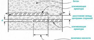
Anchoring of reinforcement in concrete (table, main standards and regulations will be indicated below) is the launching of metal rods beyond the cross-section to the length of the segment of force transfer from the rods to the reinforced concrete. That is, this is the fastening of the ends of the reinforcing rods in the thickness of the concrete.
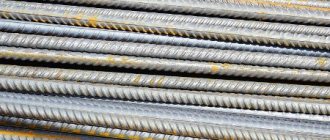
Anchoring is a very important process, the correctness of which determines the quality, strength, and ability to withstand various loads of a reinforced concrete monolith. The reinforcement is designed to strengthen the concrete structure, absorb and bear loads, and make the monolith durable, reliable and solid. Reinforcement elements can be rigid or flexible, usually made of steel or composite materials.
The size and type of fastening is largely determined by the characteristics and operating conditions of certain areas where the load is transferred from the metal rods to the material. There are several ways to perform anchoring; first, it is important to carry out the calculations correctly, determining such key parameters as the method of fastening, the length of anchorage of the reinforcement, etc.
A modern approach to anchoring reinforcement
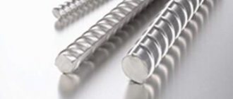
The fittings vary.
Its main goal is to strengthen the structure, make it solid and durable. Reinforcement elements can be flexible and rigid. They are made from various types of materials. The most common material is steel, but composite elements, wood, fiber, etc. are also used. Reinforcement is used exclusively in reinforced concrete products, the quality of which depends on the quality of fastening of the elements. Anchoring reinforcement in concrete is the launching of products beyond the cross-section to the length of the zone of force transfer from reinforcement to reinforced concrete; in simple terms, it is securing the ends of the rods in concrete.
Classification of reinforcing elements
Anchoring methods can be different, as well as the reinforcement used in construction. The classification of this type of product cannot be called extensive. Several types of classification are used. Depending on the conditions in which the product will be used, there are:
If we consider the product from the point of view of its intended purpose, the following classification is used:
- anchor (in this case we are talking about embedded parts);
- distribution;
- working;
- editing room
Another type of classification is to consider the orientation of the product in the structure. Here they highlight:
In this case, the purpose of the longitudinal one is to prevent the formation of vertical cracks in the most stretched zone of structures, and the transverse one prevents the formation of inclined cracks, which are characteristic of shear stresses that arise near the supports. All this provided that the concrete is good. Read more about how to improve it.
Types of anchored reinforcement
The classification of reinforcement is quite extensive, metal rods are selected according to several parameters, and the calculation takes into account maximum nuances. Depending on the operating conditions, the reinforcement can be prestressed or non-prestressed. Depending on the location in the reinforced concrete structure, it can be transverse and longitudinal.
Transverse reinforcement prevents inclined cracks from appearing and prevents shear stresses that appear near concrete supports. Longitudinal reinforcement prevents vertical cracks from propagating in certain longitudinal zones where tensile stresses are concentrated in concrete.
Classification of fittings by purpose:
- Distribution – secures the frame by welding in the position specified in the project
- Working - perceives forces that appear under the influence of the gravity of the structure, external loads, etc.
- Assembly – increases the rigidity of the reinforcement frame during assembly and transportation to the site
- Anchor – designed for attaching various types of embedded parts to a structure
Depending on the diameter of the rod and the purpose of the metal parts, the reinforcement can be rope, rod, wire (cross-section up to 10 millimeters), etc.
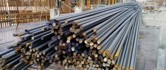
To create a high-quality reinforcement frame, only special profile rods are used. The stronger the concrete and the reinforcement suitable for the operating conditions, the more reliable and durable the reinforced concrete structure will be.
Main types of fastening reinforcement in concrete
Today in construction, several methods are used to secure reinforcement products in reinforced concrete products. At the moment, reinforcement anchoring is of the following types:
- using a specially installed transversely directed rod;
- in the form of reinforcement profile protrusions;
- using special devices installed at the ends of the rods;
- using bends at the ends of the products.
The anchorage length of the reinforcement is calculated during design. Its calculation is carried out by designers. This is an extremely important issue, a careless attitude to which is unacceptable, since the result can be disastrous, unfortunately, not only for the designer who made a mistake.
So, how to achieve the optimal figure that will ensure that the rod is included in the work? In compressed products in the anchorage area, forces will be transferred through the connection surface to the concrete area; in stretched rods, work will be done to pull out of the concrete area through the adhesion surface.
If we talk about rods of a common periodic profile (round with two longitudinal ribs and transverse protrusions in the form of helical lines), then direct anchoring is used for them. As for smooth rods, the above-mentioned loops and hooks are used specifically for this type. All these auxiliary elements, including special legs, are recommended for anchoring compressed reinforcement.
In order for the building being constructed to have a high degree of reliability, the length of the anchorage must be protected by a good layer of concrete. If the diameter of the rods exceeds 16 mm, it is recommended, in addition to the standard, to perform transverse reinforcement. If bent reinforcement is used, in order to prevent the concrete from splitting or crumbling in the place where there is a bend, special attention must be paid to the size of the bend circle of each individual rod.
Important! Both designers and those involved in construction should remember that anchoring reinforcement is a matter of safe operation of the facility under construction, which must be approached professionally and responsibly.
If it is not possible to ensure the estimated length of the anchorage, specialized anchors in the form of corners, hooks, nuts, plates, etc. are installed at the ends of the reinforcement. The attached rod can also be bent.
Do you know what the difference is between the M-500 and M-600 cement brands?
Calculation of reinforcement anchorage
When making calculations, it is necessary to take into account both the profile of the reinforcement and its class; the method of anchoring, the diameter of the rods, the strength of concrete and what the stress state at the point of adhesion will also be taken into account. In order to make accurate calculations, special formulas are used. The anchorage depth of the reinforcement and its length can also be calculated using special programs and tables. Modern designers have the opportunity to speed up the process of designing objects at all stages.
We also recommend an article on calculating reinforcement when reinforcing a concrete floor.
If anchoring of reinforcement in concrete is necessary, the table, which can be found on specialized websites or in specially developed construction programs, will help you quickly and efficiently make all the necessary calculations. If you use tables, then the calculation of the reinforcement anchorage is not required, the tables contain all the necessary data, the main thing when designing is to comply with the design requirements, that is, to carry out the design according to already laid down calculations that take into account all the details and standards.
If the anchorage length of the reinforcement is to be determined, the table that will be most acceptable and convenient should be an element of a special program in which the available data is stored. The most advanced resources take into account the class of reinforcement and class of concrete, the diameter of the rods, the type of surface of the products, the stress state and much more.
Today, anchoring reinforcement, the use of which is one of the most important construction processes, has become much easier. To avoid making mistakes, it is enough to know how to use tables correctly. It is best to order calculations from special companies that deal with this issue and provide all the necessary data within a short period of time. Correct calculations will ensure one hundred percent reliability of the structure being built, all elements of which will be in close interaction with each other.
What should be the overlap of reinforcement for tying
Joining overlapping reinforcement using knitting is the easiest way to create a reliable metal frame. For this type of connection, popular A400 rods are used. The overlapping reinforcement is mechanically joined by knitting using wire. Two rods with straight ends are overlapped and tied with annealed wire. But there are certain requirements to ensure the strength of the connection.
When joining overlapping reinforcement using the knitting method, it is necessary to take into account the following parameters:
- the amount of reinforcement overlap;
- location of the connection in the frame and its purpose;
- relative position of overlap areas.
When reinforcing the foundation, it is unacceptable to install overlapping reinforcement in places of increased load (for example, corners of a building). Therefore, it is necessary to correctly calculate the areas for overlapping reinforcement bars when tying. They should be placed in those parts of the metal structure that bear the minimum load.
If for objective reasons this condition cannot be met, the length of the overlap of the rods will depend on the diameter of the reinforcement. For a strip foundation, the areas where the overlap of reinforcement is installed must be located in places not subject to stress and bending. If this condition is not met, the length of direct anchorage is taken to be equal to 90 diameters of the reinforcement being fastened. The dimensions of such connections are strictly regulated by GOSTs.
The overlap of the reinforcement during tying also depends on the following parameters:
- class of working fittings;
- brand of poured concrete;
- purpose of reinforced concrete foundation;
- degree of upcoming load.
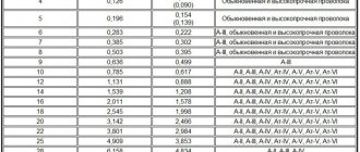
You can find out the length of the regulated length of reinforcement anchorage from the standard table provided below.
Anchoring of reinforcement: table
Attention! Clause 8.3.27 of GOST 10922 2012 states that mechanical overlapping reinforcement connections are used for metal rods with a diameter of no more than 40 mm. Areas of the reinforced frame with maximum load are prohibited from being fixed using overlaps.
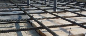
Overlapping reinforcement connection without welding when installing an armored belt
The amount of overlap of reinforcement during reinforcement is determined by a complex of factors. The diameter of the rods and the class of the poured concrete are also taken into account. The size of the overlap of the reinforcement when knitting can be calculated manually, but it is easier to navigate using the table.
Important! The length of the anchor when joining overlapping reinforcement also depends on the location of the reinforcing mesh: in the lower part of the slab (concrete tension zone), the overlap will be greater, and in the upper part of the slab (concrete compression zone) - less.
Anchoring reinforcement in concrete. Table of anchorage lengths and overlap of reinforcement in concrete
Most designers who calculate reinforced concrete structures are faced with the question: How to calculate the length of anchorage and overlap of reinforcement in concrete ? And this is really a very important question, because builders often do not pay attention to this seemingly trifle - anchoring reinforcement in concrete , and in some cases it ends in failure.
Let us understand this topic and look in detail at what anchoring reinforcement in concrete is , the length of the overlap of reinforcement , and also in this article, you can download the program and tables for anchoring reinforcement in concrete .
Anchoring is the fastening of reinforcement in concrete, which is achieved by inserting reinforcement beyond the design cross-section to a length sufficient to include the rod in the work, or by performing special constructive measures. In the anchoring zone, the tensioned rod works to pull the concrete out of the concrete body through the adhesion surface, and in the compressed rod, forces are transmitted through the adhesion surface into the concrete body.
Why is anchoring needed?
Anchoring of rods is required to ensure the design strength of the reinforcement frame and its reliable fastening in concrete. The main task when forming a long frame is to connect the ends of the rods so that they do not move from their position when mechanical stress is applied. That is, two parallel or perpendicular reinforcements will not destroy the structure, and it will be able to last much longer under conditions of various types of applied stresses than without the use of anchoring.
The quality of reinforcement fastening in a concrete structure is determined by calculating the mechanical stresses that are expected during its operation. When performing construction work, it is mandatory to adhere to technology so that there is full compliance with the calculations performed.
Anchoring can be performed for steel and composite reinforcement. It is important that the properties of strength and flexibility in reinforced areas are maintained. Otherwise, additional stresses will be created in the structure of the material, as a result of which hidden defects will form. Ultimately, the facility will become unsuitable for operation in a period shorter than the estimated period.
The basic requirements for anchoring reinforcement in concrete are established in:
- SP 52-101-2003 CONCRETE AND REINFORCED CONCRETE STRUCTURES WITHOUT PRE-STRESSING REINFORCEMENT p. 8.3.18-8.3.30
- posobiye k SP 52-101-2003 - “Manual for the design of concrete and reinforced concrete structures made of heavy concrete without prestressing reinforcement”
According to the manual to SP 52-101-2003, anchoring of reinforcement in concrete is carried out using one of the following methods or a combination of them:
— in the form of a straight end of the rod (direct anchoring);
- with a bend at the end of the rod in the form of a hook, bend (foot) or loop;
— with welding or installation of transverse rods;
- using special anchor devices at the end of the rod.
Basic anchorage length.
The basic length of anchorage of reinforcement in concrete is determined according to SP 52-101-2003 clause 8.3.21 or SP 63.13330.2012 clause 10.3.24 and SP 52-102-2004 clause 5.3.2.
The anchoring of a straight reinforcing bar in concrete occurs due to the adhesion of the profile. The basic anchorage length required to transfer the force in the reinforcement with the full design resistance value Rs to the concrete is determined by the formula:
,
where A s and u s are, respectively, the cross-sectional area of the anchored reinforcement bar and the perimeter of its cross-section, determined by the nominal diameter of the bar;
Rbond is the calculated adhesion resistance of reinforcement to concrete, assumed to be uniformly distributed along the length of the anchorage and determined by the formula
,
here Rbt is the design resistance of concrete to axial tension;
h1 is a coefficient that takes into account the influence of the type of reinforcement surface.
h2 - coefficient taking into account the influence of the size of the diameter of the reinforcement, taken equal to:
— for non-prestressed reinforcement:
h2 =1.0 - with reinforcement diameter d s £32 mm;
h2 =0.9 - for reinforcement diameters of 36 and 40 mm;
— for prestressed reinforcement:
h2 =1.0.
From where you can derive: , where d s is the diameter of the reinforcement.
| h1 – for non-prestressed reinforcement | |
| For smooth reinforcement (AI, A240) | 1,5 |
| For cold-deformed reinforcement of periodic profile (B500S, A500Skhd) | 2,0 |
| For hot-rolled and thermomechanically strengthened reinforcement of periodic profile (A400C, A500C, A600C) | 2,5 |
| Thermomechanically strengthened A500SP (STO 36554501-005-2006) with an effective profile (crescent four-sided) | 2,8 |
| h1 – for prestressed reinforcement | |
| For cold-deformed periodic profile reinforcement of class BP1500 with a diameter of 3 mm and reinforcing ropes of class K1500 with a diameter of 6 mm; | 1,7 |
| For cold-deformed reinforcement class BP with a diameter of 4 mm or more | 1,8 |
| For reinforcing ropes class K with a diameter of 9 mm or more | 2,2 |
| For hot-rolled and thermomechanically strengthened reinforcement of periodic profile (A400C, A500C, A600C) | 2,5 |
Anchoring of working reinforcement in the concrete of the element
Anchoring of working reinforcement in the concrete of the element
A
— adhesion of straight rods to concrete;
b
- hooks;
c
- paws;
g
- loops;
d
- welding of transverse rods
- Direct anchorage of reinforcement and tabs are used only for periodic profile bars.
- For smooth bars, hooks and loops should be used.
- Claws, hooks and loops are not recommended for use with compressed reinforcement.
- Along the length of the anchorage there must be a sufficient protective layer of concrete and in some cases, especially with rods with a diameter of 16 mm or more, transverse reinforcement.
- When using bent reinforcement (bends, bends of the ends of bars), the minimum diameter of the bend of an individual rod must be such as to avoid destruction or splitting of concrete inside the bend of the reinforcing bar and its destruction at the point of bend.
Special measures to ensure anchoring if it is impossible to ensure the estimated anchorage length include:
— arrangement of special anchors at the ends of the rods in the form of plates, washers, nuts, angles, upset heads, etc.;
— bending the anchor rod 90° along a circular arc with a clear radius of at least 10 d
*(1 ¾
ll / lan )
and no less restrictions for bent reinforcement (see above) with the installation of clamps on the bent section to prevent the extension of the rods.
Direct anchoring.
Direct anchoring of reinforcement is arranged in places where the geometry of the structure allows this, and can sometimes be located in a protective layer of concrete. Direct anchoring is allowed only for periodic profile reinforcement.
The presence of additional compression of concrete from external force factors in the anchoring zone increases the bearing capacity of the concrete itself, thereby increasing the effectiveness of anchoring (adhesion).
When directly anchored in a concrete protective layer, the longitudinal force tries to chip away at the protective layer through shear stresses.
Rice. 1 . Possibility of chipping the protective layer of concrete during anchoring.
Our standards do not stipulate the length of anchorage depending on the location of the rod in the structure, therefore anchoring in the protective layer of concrete is not recommended without the presence of transverse reinforcement or some other additional measures (increased anchorage length, installation of upper perpendicular longitudinal or transverse reinforcement, increase in the protective layer , bending device, etc.), with the help of which shear stresses will be perceived and chipping of the protective layer of concrete will be excluded.
Installing perpendicular longitudinal reinforcement along the top in the anchoring zone increases the chipping area of the protective layer of concrete, but its use is less effective than installing transverse reinforcement.
The pitch and diameter of the clamps in the area of direct anchoring in the protective layer of concrete is determined depending on the type of clamp and the diameter of the longitudinal reinforcement.
The estimated length of direct anchorage of reinforcement in concrete is determined
(SP 52-101-2003 clause 8.3.22 or SP 63.13330.2012 clause 10.3.25):
For elements made of fine-grained concrete of group A, the required design anchorage length must be increased by 10ds for tensile concrete and by 5ds for compressed concrete.
It is allowed to reduce the length of direct anchorage of non-prestressing reinforcement bars depending on the number and diameter of transverse reinforcement in the anchoring zone, the type of additional anchoring devices (welding of transverse reinforcement) and the amount of transverse compression of concrete in the anchoring zone (for example, from the support reaction), but not more than thirty%.
In any case, the actual anchoring length is taken to be no less than 15 d s and 200 mm, and also no less than 0.3 × l o,a n .
Design length of direct anchorage of tensile (non-prestressed) reinforcement at k=1 class A400:
| Concrete compression class | Lan/ds | Anchoring length (mm) depending on the diameter of the reinforcement | |||||||||||
| 6 | 8 | 10 | 12 | 14 | 16 | 18 | 20 | 22 | 25 | 28 | 32 | ||
| B15 | 47,32 | 284 | 379 | 473 | 568 | 663 | 757 | 852 | 947 | 1041 | 1183 | 1325 | 1515 |
| IN 20 | 39,41 | 237 | 315 | 394 | 473 | 552 | 631 | 710 | 788 | 867 | 985 | 1104 | 1262 |
| B25 | 33,77 | 203 | 270 | 338 | 405 | 473 | 540 | 608 | 676 | 743 | 844 | 946 | 1081 |
| B30 | 30,84 | 200 | 247 | 309 | 370 | 432 | 494 | 555 | 617 | 679 | 771 | 864 | 987 |
| B35 | 27,28 | 200 | 218 | 273 | 328 | 382 | 437 | 491 | 546 | 600 | 682 | 764 | 873 |
Design length of direct anchorage of tensile (non-prestressed) reinforcement at k=1 class A500:
| Concrete compression class | Lan/ds | Anchoring length (mm) depending on the diameter of the reinforcement | |||||||||||
| 6 | 8 | 10 | 12 | 14 | 16 | 18 | 20 | 22 | 25 | 28 | 32 | ||
| B15 | 58 | 348 | 464 | 580 | 696 | 812 | 928 | 1044 | 1160 | 1276 | 1450 | 1624 | 1856 |
| IN 20 | 48,32 | 290 | 387 | 483 | 580 | 677 | 773 | 870 | 967 | 1063 | 1208 | 1353 | 1546 |
| B25 | 41,41 | 249 | 332 | 414 | 497 | 580 | 663 | 746 | 828 | 911 | 1035 | 1160 | 1325 |
| B30 | 37,81 | 227 | 303 | 378 | 454 | 530 | 605 | 681 | 756 | 832 | 945 | 1059 | 1210 |
| B35 | 33,44 | 201 | 268 | 335 | 401 | 468 | 535 | 602 | 669 | 736 | 836 | 937 | 1070 |
Design length of direct anchorage of tensile (non-prestressed) reinforcement at k=1 class A500SP with an effective profile:
| Concrete compression class | Lan/ds | Anchoring length (mm) depending on the diameter of the reinforcement | ||||||||||
| 6 | 8 | 10 | 12 | 14 | 16 | 18 | 20 | 22 | 25 | 28 | ||
| B15 | 53,56 | 322 | 429 | 536 | 643 | 750 | 857 | 964 | 1071 | 1179 | 1339 | 1500 |
| IN 20 | 44,63 | 268 | 357 | 446 | 536 | 625 | 714 | 804 | 893 | 982 | 1116 | 1250 |
| B25 | 38,25 | 230 | 306 | 383 | 459 | 536 | 612 | 689 | 765 | 842 | 956 | 1071 |
| B30 | 34,94 | 210 | 280 | 350 | 419 | 489 | 559 | 629 | 699 | 769 | 874 | 979 |
| B35 | 30,91 | 200 | 247 | 309 | 371 | 433 | 495 | 557 | 618 | 680 | 773 | 866 |
Note: the ratio in the tables Lаn/ds for non-prestressed reinforcement with a diameter greater than 32 mm must be divided by a factor of 0.9.
Anchoring the longitudinal rod using special devices
1
- concrete;
2
—anchored rod;
3
- round or square steel washer;
4
- welding;
5
- compression;
6
— planted head;
7
— steel corner;
8
- thread
Displacement of reinforcement bars when connecting without welding
Displacement of reinforcement bars when connecting without welding
Adjacent reinforcement connections along the length must be spaced apart so that no more than 50% of the reinforcement is simultaneously connected in one section. As one design section of the element considered to determine the relative amount of abutting reinforcement in one section, a section along the abutting reinforcement with a length of 130% of the overlap length of the rods is taken. It is considered that reinforcement joints are located in the same design section if the centers of these joints are located within this section [Section 6.1 of the design manual “Reinforcement of elements of monolithic reinforced concrete buildings” (Moscow 2009)]
The length of the anchorage depends on the profile and diameter of the rod, the stress state of the concrete in the anchorage zone (compression/tension), the presence of transverse reinforcement in the anchorage zone, the actual stress in the rod relative to its maximum value and other design factors.
Anchoring methods
There are several ways to secure reinforcement in reinforced concrete. The following types of fastening are distinguished:
- using devices installed on the edges of reinforcing elements;
- installation of reinforcement in the form of protrusions for straight structures;
- using transverse elements made of metal;
- by installing special loops, tabs or hooks.
Only for reinforcing products with a periodic profile, fastening of straight components is provided. By increasing the strength of concrete, it is possible to significantly increase the adhesion of the concrete mixture to the anchorage. The quality of fastening will also be affected by the presence or absence of lateral compression. According to the technology, the use of special hooks is permitted only for reinforcement with a smooth surface. Claws are used for reinforcing elements with a periodic profile.
In cases where construction loops are chosen for anchoring, it is important to maintain equal amounts of stretch at both ends. Neglecting this rule will lead to a significant reduction in the adhesion of the elements. If increased structural strength is needed, which the above methods cannot provide, devices are used for individual reinforcing bars and the fastening is strengthened by welding the transverse elements. To do this, take rods with a cross-section of 6 mm and use 2-4 transverse elements.
Requirements of regulatory documents for reinforcement connections
SNiP state that a concrete foundation must be reinforced with at least two reinforcement cages. For private construction, overlapping reinforcement joining methods are more often used, since this method is budget-friendly and more affordable, and does not require a hydraulic installation or a welding machine. To connect using this method, it is recommended to use reinforcement with a diameter of no more than 40 mm.
The distance between the rods , which are connected by overlap welding, must be more than 25 mm, which allows the concrete to penetrate into all narrow places in the structure. For rods with a diameter greater than 25 mm, a distance equal to the diameter of the reinforcement should be maintained.
The distance between the reinforcing rods along the width of the foundation should be no more than 8 sections of these rods. If the reinforcement is overlapped using knitting, then the distance between the rods is zero: it is determined only by the profile protrusions. The greatest distance in this case should be no more than 4 diameters of the reinforcing bars.
The distance between the joints themselves, located nearby, is taken to be 30 mm or more.
Expert advice
Experts recommend using pressed joining of reinforcement, rather than overlapping or screw couplings, if you need to connect rods with a cross-section larger than 25mm. These types of connections allow:
- increase the level of safety of the structure due to increased joint strength;
- reduce the cost of reinforcement, since the overlap method provides for up to 25% additional waste of reinforcement.
Length and features of its calculation
To correctly calculate the length of reinforcement, many indicators are taken into account. It is important to maintain the required value that will be embedded in reinforced concrete. Calculations are made with maximum accuracy. To determine the anchorage length, designers use graphs based on the stress in the bars and the class of the reinforcing elements.
Any specialist in the field of construction can work with schedules. The recommended length of the reinforcing bar is determined as follows:
- Determine the amount of stretching of the product along the abscissa axis.
- Lower the line to the desired grade of concrete.
- Find the point of intersection of the perpendicular from the abscissa axis with the resulting segment.
- Having designated the point Ra, draw a parallel to the ordinate axis.
- The resulting point will indicate the optimal length of the reinforcing bar.
The same technique is used to work with other charts. If it is impossible to maintain the recommended fastening length, it is necessary to equip the edges of the reinforcement with special elements. Such devices act as anchors. Fasteners are made in the form of plates, hooks and corners.
Indicators for calculation
To calculate the anchorage length of reinforcing elements as accurately as possible, the following data is taken into account:
- reinforcement section;
- profile type;
- brand of concrete;
- length of the structure and depth of laying of reinforcing elements;
- rod embedding method;
- tension at the coupling point.
The table allows you to quickly calculate the value. It may include different indicators. Similar tables are included in programs for calculating anchorage on a PC. The use of such techniques is acceptable for non-professional construction. In the professional sphere, this is how preliminary calculations are carried out. The final indicator is calculated using formulas.
To carry out calculations using formulas, you must have an engineering education and experience in the field of construction. Beginning builders can:
- use the services of specialized companies;
- determine the approximate value using tables, graphs and programs.
Considering the fact that the final result of construction and the strength of the structure depend on high-quality anchoring, it is recommended to order calculations from specialized companies. It is better to pay for the work of specialists than to waste expensive building materials.