Mold manufacturing technologies
TO
category:
Foundry
Mold manufacturing technologies
Next: Drying, finishing and assembling molds
Currently produced castings are characterized by great diversity, which necessitates the use of various casting molds and materials.
1. Classification of casting molds
Casting molds are classified according to the material from which they are made and the condition when poured.
Single-use molds are used to shape only one casting, after which they are destroyed. Molds are made from sand-clay, sand-resin and other mixtures.
One-time molds can be wet (wet molding), dry (dry molding), dried, chemically cured, and assembled from dry or cured cores.
Raw forms, due to their low cost, simplicity and speed of production, and the absence of a drying process, are most widely used. They are used for castings of simple and medium complexity from cast iron, steel and non-ferrous alloys weighing up to 1500 kg.
Dry molds are designed for the production of medium and large castings with a large amount of machining. A well-dried, durable mold coated with non-stick paint ensures high-quality castings. However, a long drying cycle (6-36 hours or more), significant fuel consumption, and the increased labor intensity of knocking castings out of molds make them uneconomical. They are being replaced by surface-dried and chemically cured forms.
Dried molds are made from molding sands containing the binders SP, SB, and KT. These molds are used for critical castings of iron and steel weighing from 1000 to 8000 kg. The drying time for such forms is 10 times less than for conventional dry forms.
Chemically curable molds are intended for the production of castings from steel, cast iron and non-ferrous alloys weighing 100 tons or more. There are two varieties of such forms: some are cured by blowing or blowing them with carbon dioxide, and the second are self-curing - with short-term exposure in the workshop atmosphere.
In the last decade, the process of chemical hardening of molds has become widespread, based on the use of liquid self-curing molding mixtures (LSM), containing liquid glass as a binder and its hardening accelerator (catalyst) - ferrochrome production slag.
Reusable (semi-permanent) molds are used for the production of medium and large castings of simple configuration weighing up to 15 tons. These molds are made from a highly refractory mixture consisting mainly of fireclay, molding clay and quartz sand. After appropriate heat treatment, the durability of the molds reaches 25-40 removals.
Reusable molds also include metal molds for castings from various alloys of simple and medium complexity, small and medium in weight and size (in serial and mass production).
Rice. 1. Device for template molding.
2. Forming tools and accessories
In the manufacture of molds and cores, various tools, flasks and devices are used.
Tool. The most complete set of tools is used when molding by hand. The technical specifications for the tool are regulated by GOST 801-74.
To sow the model with the facing mixture, rectangular sieves with a metal mesh with cells of 2-6 mm are used. Rectangular shovels are used to fill the flask mixture, and shovels with a pointed end are used to dig holes in the soil when molding.
The mixture in the flasks is compacted with various tampers: - when working on workbenches - with a short tamper (300 mm long). The handle of such a rammer is made of aluminum alloy, and the wedge-shaped and flat shoes are made of St. 40 or from oil-gasoline-resistant rubber grade A of increased hardness; — when compacting the mixture in medium and large flasks, the most productive is a pneumatic tamper. Its shoes are made of cast iron grade SCh18-36 or, preferably, from oil- and petrol-resistant rubber grade A of increased hardness.
The rammer is driven by compressed air at a pressure of 5-6 kgf/cm2.
Smoothers are used to smooth out shapes. In places inaccessible to smoothers, lancets are used for these purposes. Finishing of concave surfaces and recesses is done with double-ended spoons. Smoothing of shallow cylindrical surfaces, corners of fillets and other curved surfaces is carried out with shaped smoothers. The remaining particles of the mixture are removed from deep cavities with hooks.
Sand is swept away from the model and surfaces of the molds with a hair brush, which is also intended for painting and washing large molds. The best quality of painting is obtained when using a spray gun.
Ventilation of the molds is carried out using air vents - needles of different diameters.
Rice. 10.2. Types of flasks. deeds in the form of implementation
Large models are pushed with a metal hammer, and special steel plates must be cut into the model to protect it from damage. Models are removed from mold halves using pointed and screw lifts.
When molding according to a template with a vertical axis of rotation, use the device shown in Fig. 10.1. It consists of a thrust shoe, a spindle, a locking ring and a sleeve on which the template is secured.
The investment rings must have high strength, rigidity and minimal weight. They are made from cast iron grades no lower than SCh15-32, low-carbon steel 20L - ZOL-1, aluminum and magnesium alloys.
The flasks are either solid cast or welded. According to the configuration, rectangular, shaped and round flasks are distinguished.
Depending on the weight, they are divided into manual, combined and crane. Manual flasks without mixture weigh up to 30 kg, and with mixture - no more than 60 kg; combined without mixture - from 31 to 60 kg, and with mixture - more than 60 kg; cranes both without mixture and with mixture - over 60 kg.
For precise assembly of half-forms, pins are used, made from steel grades 40-45 with hardening and subsequent grinding. There are removable and permanent pins. The latter are strengthened in the ears of the lower flask, and in large flasks - in the shelves of the longitudinal walls. Removable pins are most used in machine molding.
For interchangeability of flasks, centering holes in their ears are drilled along the jig. Hardened steel bushings are pressed into these holes, which makes it possible to replace them when worn out and thereby ensure the accuracy of mating of the flasks.
When choosing the dimensions of the flasks, one should proceed from the smallest permissible thicknesses of the molding sand in different areas of the mold.
3. Making molds by hand
When molding by hand, casting molds are made from wooden solid and split models, model plates, skeletal models and templates.
4. Molding in soil
When molding in soil, the most important operation is preparing the lower part of the mold - the bed. There are two types of bed: soft and hard.
Soft bed. When making single small castings, a bed in the soil is prepared for each of them. When producing a series of castings of the same type, a hole is dug in the floor of the foundry with a depth of 100-125 mm greater than the height of the model and dimensions exceeding the dimensions of the model by 200-250 mm on one side. Four piles of the mixture are left at the bottom of the pit; a wooden slat is laid on two of them, and a lath on the other two.
A ruler is placed on these slats and the horizontal position is checked using a spirit level. Then the slats are covered with the mixture, compacted and their horizontal position is checked again. After this, the space between the slats is filled with spent molding sand, it is leveled, and the excess is raked off with a ruler. Bars 10-12 mm high are placed on the slats, and a layer of sifted facing mixture is applied to the layer of waste mixture.
Having removed the bars, compact it as follows: the first molder presses the ruler against the rail, and the second, raising and lowering the other end of the ruler, compacts the mixture over an area of 300-400 mm. After this, the second molder presses the ruler against the rail, and the first compacts the mixture.
The final leveling of the surface and removal of grooves is achieved by moving the ruler along the slats. The leveled surface is covered with a thin layer of facing mixture. The model is laid face down on the resulting bed and, with blows of a hammer or tamper, it is pushed down through the intermediate gasket.
A hard bed is used in the manufacture of molds for medium and large castings. A hole is dug in the floor of the workshop 300-400 mm deep than the height of the model. The bottom of the pit is compacted tightly, a layer of sifted soot or broken brick 150-200 mm thick is poured onto it, lightly compacted and leveled with fine soot.
Rice. 3. Scheme for making a soft bed.
Rice. 4. Scheme for making a hard bed: 1 - layer of burning; 2— ventilation ducts; 3— facing layer of the mixture; 4 - ventilation pipes.
The surface of the layer is leveled with a ruler and then a 9 mm diameter stifle is used to prick the ventilation ducts down to the cinder bed.
The bed prepared in this way is sowed with a layer (40-50 mm) of the facing mixture. After compaction, the ventilation ducts are also punctured in it with a 3-4 mm diameter air vent.
5. Molding in paired flasks
The greatest dimensional accuracy of castings is achieved when molding in flasks. Molding in paired flasks has become widespread. Molding of castings with complex configurations is carried out in three, four or more flasks. An example of making a tee casting in paired flasks is shown in Fig. 5.
The molding process begins with the manufacture of the lower half-mold. The lower half of the model and two feeders are placed on the under-model shield, and a layer of facing mixture is applied to the model and pressed by hand. The filling mixture is poured into the flask and compacted. After cleaning off the excess mixture, prick the ventilation ducts with a damper.
The resulting half-mold is fastened to the under-model shield and turned 180°, placed on the loosened platform of the molding platform, lightly ground in, after which the shield is unfastened and removed. Then they smooth the fret, sprinkle it with dry quartz sand and blow the sand off the model. Having placed the upper half of the model and the slag catcher, the models of the riser and vents are installed.
Rice. 5. Molding in paired flasks: 1 - lower half-mold; 2 — upper half-form; 3 - rod.
After this, the upper half-mold is made in the same sequence.
Its compaction should be uniform, without local weaknesses or overconsolidation. The degree of compaction of the mixture is checked with a hardness tester. It depends on the mass and height of the casting.
To increase the strength of the upper half of the mold, it is reinforced with steel hooks or wooden pegs - “soldiers”, previously moistened with liquid clay.
By taking out the model of the riser and thrusts, you can open the mold. When molding small models, after compacting the mixture, the halves of the model are held in the half-mold and do not require additional fastening. When molding medium and large heavy models, the friction between the molding sand and the model is not enough to hold it in the upper half of the mold and additional strengthening is necessary. Having secured the model by lifting it to the upper flask, open the mold, remove the halves of the models and finish the upper and lower halves of the mold, then install the core and assemble the mold.
6. Molding using model plates
With this molding method, the lower and upper halves of the mold are made separately using two model plates.
It is advisable to carry out molding on plates in small-scale production. At many Leningrad enterprises - in the associations named after Karl Marx, named after Ya. M. Sverdlov, Nevsky Plant named after V. I. Lenin, etc. - it is successfully used in small-scale production of relatively large-sized castings (more than 3 m long and weighing up to 3 T).
Separate molding by slabs ensures: - increased accuracy of castings; — increase in labor productivity by 15-20% due to the reduction of finishing operations; - the ability to manufacture models from individual parts and then assemble them on a model plate; — increasing the removal of castings from the molding area by 1.5 times due to the installation of molds in 2-3 floors with a shift.
For small-scale production, slabs made of durable wooden panels are used, and for mass production, planed cast iron is used. Model plates can be used repeatedly.
A set of model plates for the manufacture of castings for the body of a medium-sized textile machine (920X420X400 mm) is shown in Fig. 6.
Molding work is carried out by a team of two molders. To reduce worker fatigue, model slabs are installed on low trestles.
Rice. 6. A set of model plates for molding the body: a - plate for the lower half of the mold; b - plate for the upper half of the mold; 1 - plate; 2 — centering bushings; 3—model.
The work is carried out in the following sequence: - cleaning the model and slab and applying a release agent; — installation of the bottom and top flasks on the slabs; — applying the facing mixture to the model, installing hooks (in the upper half of the mold) and compressing the mixture; — filling the flasks with the filling mixture, compacting it, removing excess and pricking the ventilation ducts; — fastening model plates with flasks and their edging; installation of the lower half-mold on the prepared platform, detaching the model plate, removing it and finishing (if necessary) - half-molds; — installation of rods; — detaching and removing the top plate, finishing (if necessary) the half-mold; - form assembly.
A cast iron plate (sometimes a wooden one) is placed on the assembled half-mold, on which a second mold is installed with a slide for installing the sprue bowl.
7. Chemically curing and large shell forms
When making molds using the CO2 process, liquid glass is introduced into the molding mixture as a binder. The facing layer of the liquid glass mixture is applied to the model in a layer of 20-40 mm, and the rest of the flask is filled with the filling mixture. All mold manufacturing operations are performed in the same sequence as when molding using sand-clay mixtures. After removing the model and finishing the mold, it is purged with carbon dioxide, which quickly cures it. Then the form is assembled.
Chemically curing mixtures are also used in the manufacture of large shell molds, which are used in the production of medium and large castings. A mold for steel casting of a rolling mill pad weighing 10 tons is shown in Fig. 7.
The shells are made from a carefully processed split wooden model rubbed with graphite.
The process consists of the following operations: — the lower half of the model is laid on a planed under-model panel; - a collapsible wooden jacket is installed on it, in the walls of which holes with a diameter of 9-10 mm are drilled. The distance between the walls of the jacket and the model should be approximately 120-150 mm; — a welded frame is installed in the gap between the model and the jacket to strengthen the shell; — the liquid glass mixture is poured into layers 80–100 mm high, compacted, and steel rods with a diameter of 8 mm are placed between the individual layers of the mixture to form purge channels, which should not reach 20–25 mm from the model; – excess mixture is cleaned from the horizontal surface and purge channels are punctured; — remove the steel rods and blow the resulting shell with carbon dioxide through the purge channels; — the cured shell, together with the model and jacket, is turned 180°; - remove the model, open the wooden jacket and remove it.
The upper shell is made in the same sequence.
The half-molds are assembled in a frame consisting of two flasks without ribs. The lower flask is placed on a leveled area and seeded with a filling mixture, which is then compacted. The bottom shell is installed on the resulting bed and the gaps between it and the flask are filled with a dry mixture. A shell rod is installed in the shell marks, the top shell and the second flask are applied and covered with a 150 mm layer of dry mixture.
Rice. 7. Combined form with shell inserts: a - lower shell; b - upper shell; c — shell rod; g - assembled form; d - casting.
The rest of the flask is filled with metal balls with a diameter of 40 mm. Before pouring, the mold is additionally loaded with weights.
The use of shell molds, cured before models are removed from them, makes it possible to obtain shells with working surface sizes corresponding to the dimensions of the model. In addition, models of such forms are made collapsible, which makes it possible to eliminate molding slopes on them, which require additional metal consumption.
8. Pattern molding
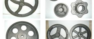
Pattern molding is carried out in the production of single medium and large castings having the external shape of bodies of rotation of a simple configuration (bowls, flywheels, pipes, pipes with flanges, etc.),
The following types of template molding are distinguished: with a vertical spindle, with a horizontal spindle and by broaching blocks. Forming with a vertical spindle is most widespread. Let's consider it using the example of shaping the casting of a bowl of grinding runners.
For template molding of a bowl (Fig. 8, a) the following is required: a machine with a vertical axis, a template measure (Fig. 8, b), templates for sharpening a block with a body (Fig. 8, c) and a bowl block (Fig. 8, d ), models of ribs (Fig. 8, e) and a hub with a center hole (Fig. 8, f). Molding is carried out in the soil (with a hard bed) under the upper flask.
Rice. 8. Devices for template molding of the runner bowl.
The process consists of a number of stages. At the first stage, a block with a body is sharpened, which will serve as a model for making the upper half of the mold; on the second, operations for the manufacture of the upper half-mold are carried out; on the third, the lower half of the mold is sharpened; on the fourth, the mold is finished and assembled; on the fifth, the mold is loaded, the castings are poured and knocked out.
9. Molding according to the skeletal model
In a single production of large castings, in order to reduce the cost of making models, skeletal models are used, the thickness of the ribs is assumed to be equal to the thickness of the walls of the casting.
A skeletal model for making a large bathtub casting is shown in Fig. 9, a, and the molding diagram is in Fig. 9, b. The model is molded in a flask or in soil. The internal cavity is smoothed at the level of the bars and the resulting surface is covered with paper. Then the upper half-mold with the block is made. After the split, the upper half of the mold is trimmed, and the release paper in the lower half is removed, the mixture compacted between the ribs is slightly loosened, and a layer of the mixture to the thickness of the ribs is removed using a rake template. After this, the model is removed and the production of the mold is completed in the usual way.
Rice. 9. Scheme of molding according to the skeletal model.
10. Molding in clay on brick
Brick molding in clay is carried out in the production of such large castings as molds, ladles, boilers, large diameter pipes, etc. Molding is carried out according to a model, frame model or template.
The sequence of making a mold and a rod for casting a large pipe is shown in Fig. 10. In a solid bed, install a thrust bearing, a spindle and a sleeve on which the template is strengthened. Check the correct installation of the spindle with a spirit level. A layer of clay is applied to a cast iron pan and the first row of red brick masonry is laid out. A layer of clay 15-20 mm thick is applied to it and a second row is laid out, overlapping the seams in the first row.
To increase gas permeability, fine cinders are laid between the rows of bricks, granulated cupola slag, straw bundles, and ventilation channels are made in the dried clay with a choke. To increase the strength of the masonry, cast iron slabs are laid every 5-6 rows, connected to the bottom pallet and to each other with ties.
The correctness of the masonry is checked using a template. There should be a gap of 20-25 mm between the working edge of the template and the masonry surface. The inner surface of the masonry is lined with clay and the working surface is sharpened with a template. After air drying for a short time, remove the template and spindle and dry the mold with a portable dryer. Then the cracks are sealed, the form is painted and dried a second time.
Rice. 10. Making a brick mold and a rod according to a template: a - making a mold; b - production of the rod; c - assembled form; g—casting; 1 — thrust bearing; 2— spindle; 3— pallet; 4 - supports; 5 - brickwork; 6—template for sharpening the mold; 7 - gating system; 8 - facing clay.
The process of making a core is similar to the process of making a mold. Dry the rod in a dryer.
Brickwork is carried out in special caissons or flasks with the gaps between the masonry and the wall of the flask filled with molding mixture. Such forms can be used repeatedly for small intermediate repairs.
Modern methods of making large molds by hand
The continuous growth in the production of large castings requires improvement of technological processes and working conditions, reduction of the labor intensity of manufacturing castings during manual molding, let's consider some rational processes for shaping castings developed by foundries of the Leningrad associations named after Ya. M. Sverdlov, Nevsky Plant named after V. I. Lenin and other enterprises.
Metal beds. When molding large castings, hard sand-clay beds are used, and when making especially large castings, the bed is made of brickwork. When the casting is removed from the mold, the bed is partially destroyed, and before each molding it is necessary to spend a lot of time repairing it.
Rice. 11. Scheme for preparing a solid metal bed: 1 - layer of burning; 2 - metal plate; 3 - gas outlet pipes; 4 - caisson; 5—upper half-form.
A form with a metal bed, made in a caisson, is shown in Fig. 11. The gaps between the walls of the caisson and the model are determined by the convenience of filling the mold. The bottom of the caisson is covered with an even layer of burning, on top of which a cast-iron plate is placed, forming a rigid metal bed.
Replacing the upper half of the mold with rods
To avoid leakage of metal during pouring, cushioning clay is usually used, as a result of which bays are formed on the casting, the removal of which requires the labor of trimmers and wastes metal. When replacing the upper half of the mold with overlapping rods, sand cushions began to be used instead of cushioning clay. For this purpose, in the horizontal marks of the rods through which gases are removed, recesses of 20-25 mm are made, filled with damp sand with some overestimation. When installing the covering rods, the sand is compacted, thereby creating reliable insulation of the ventilation ducts and tight contact between the rods, eliminating the possibility of bays.
Rice. 12. Technology for manufacturing large forms: a - old technology; b - new technology: 1 - lower soil half-forms; 2— upper half-form; 3 - cushioning clay; 4 — loading plate; 5 — rod replacing the upper flask half; 6 — ventilation risers; 7 - sand cushions.
As a result of the introduction of new technology, the dimensional accuracy of castings has increased, metal consumption has been reduced, the stock of flasks and the need for drying bulky half-molds have been eliminated, and the labor intensity of trimming operations has decreased. Molding according to a block model. When producing small series of medium and large castings, it is advisable to combine two similar models into one block, connected by a dividing rod.
Making molds from liquid self-hardening mixtures. These mixtures are widely used in the manufacture of large rods. Thus, in the foundries of the association named after Ya. M. Sverdlov, all rods for castings weighing more than 3 tons are made from LSC.
Practice has shown that these mixtures can also be successfully used in the manufacture of molds for large castings. The molding scheme in ZhSS is shown in Fig. 14. The model is installed on bricks or on special supports fixed to it, or fixed in the caisson using planks. There should be a gap of 100-150 mm between the model and the walls of the caisson. The model has hatches for filling LCS. To improve the filling of the mold, the mixture is squeezed out of the hatches using pushers. After filling the space under the model with the mixture, it is poured along the perimeter of the caisson into the gaps between its walls and the model. 35-40 minutes after pouring the LSS, the model can be removed and finishing of the mold can begin.
The working surface of the mold has significant porosity. To eliminate it, special paint is applied to the surface and dried with a burner for 2–4 hours at a temperature of 200–220 °C.
The manufacturing technology of a complex shape for casting a cast iron model of a blade weighing 35 tons is shown in Fig. 15. This model is designed for forming large steel blade castings. Molding is carried out using a wooden model equipped with stops along which the model is placed on a bed in a caisson. A removable frame is placed on the model, shaping the contours of the dummy. To prevent floating, the model and frame are loaded.
Filling of LSC is carried out through the hatches available in the model and the removable frame, and into the gaps between the walls of the caisson and the removable frame. Then the mixture is pressed using pushers. After a short exposure, the removable frame is removed, the mixture is removed from the hatches, it is trimmed around the model, the surface of the half-mold is covered with release paper and secured with pins, after which they proceed to the design of the upper half-mold (the block-rod).
Rice. 13. Technology for making molds using a block model a - soil form; b - rod form.
Rice. 14. Scheme for manufacturing a mold from ZhSS.
Rice. 15. Technology for manufacturing large molds using
12. Machine molding
Mechanized extraction and models without preliminary splitting ensures high-quality molds, increases the accuracy of castings and reduces scrap. The introduction of coordinate and type-setting frame plates makes it standard to use machine molding not only in serial and mass production, but also in small-scale and individual production.
Typically, a casting mold is made on two machines: one for the lower half of the mold, and the other for the upper half. In mass and serial production, metal models and elements of the gating system are mounted on one-sided cast iron plates, and in small-scale and single production, wooden models
strengthened on coordinate plates or in type-setting plates-frames. The model on the coordinate plate and in the frame plate is replaced at the workplace within 20-30 minutes.
Based on the method of compacting the mixture in the flask, a distinction is made between pressing machines with bottom and top pressing, shaking machines, shaking machines with pre-pressing and sand-throwing machines.
Compaction of the mixture on machines with bottom pressing. The operating diagram of such a machine is shown in Fig. 17. A table is attached to a press piston placed in a cylinder. There is a model plate on it, moving in a stationary frame. The flask is placed on the pins of a stationary frame and filled with the mixture, leveling it over the entire Surface. After this, the flask with the mixture is placed under a stationary crossbeam. When compressed air is supplied to the cylinder, the press piston rises, the model is introduced into the mixture and compacts it. When the air supply stops, the piston is lowered and the model is removed.
With bottom pressing, the highest density of the mixture is created at the model and decreases towards the top of the flask, increasing slightly at the traverse, which is the advantage of this method.
The large power consumption to overcome the friction force of the mixture against the walls of the flask limits the scope of application of these machines. They can be used for flasks with clear dimensions up to 1100X800 mm and heights up to 150 mm.
Compaction of the mixture on machines with top pressing. The operating diagram of this machine is shown in Fig. 18. A table is attached to a press piston placed in a cylinder, on which a plate with a model is located. After installing the flask with the filling frame and filling them with the molding mixture, compressed air is supplied to the cylinder at a pressure of 6 kgf/cm2. Under the influence of air, the piston, together with the table and the modeling equipment mounted on it, rises upward, while the pressing block, mounted on the traverse, is inserted into the filling frame and compacts the mixture in the flask.
After the supply of compressed air to the cylinder stops, the table lowers under the influence of its own gravity.
Compaction of the mixture on shaking machines. This method of compacting the mixture, despite some inherent disadvantages, is the most common, as it makes it possible to produce molds for complex large castings in flasks, with clear dimensions of 3000 X 2000 mm and a height of up to 750 mm.
Rice. 16. Types of model plates: a - one-sided; b - coordinate: c - typesetting plate-frame; 1 - main plate; g - insert model plate; 3 - model, 4 - slag catcher; 5 - riser; 6—thrust screws.
Rice. 17. Scheme of operation of a machine with bottom pressing.
In Fig. Figure 19 shows a diagram of the operation of a shaking machine with pre-pressing. It has two cylinders: a pressing and a shaking cylinder, the latter serving as a piston for the first. Inside the cylinder there is a shaking piston on which the table is mounted. A model plate with a model is mounted on the table.
A flask with a frame is installed along the pins onto the model plate. After filling the flask and frame with the mixture, compressed air is supplied to the cavity of the shaking cylinder, under the pressure of which the shaking piston rises. In this case, the inlet hole is blocked by the side surface of the piston, and the exhaust hole opens, and the air escapes into the atmosphere.
The table with the model plate and the flask under the influence of its own gravity falls onto the end of the cylinder, so upon impact the molding mixture in the flask is compacted. When the piston is lowered, the inlet port opens again and the cycle repeats. Typically the table rises to a height of 30-80 mm and makes 30-120 beats per minute. To compact the mixture, 20-40 blows are enough.
After the shaking process is completed, compressed air enters the cavity of the press cylinder, and the model plate and equipment come into contact with the press block mounted on the traverse. The block enters the cavity of the filling frame and compacts the upper layers of the mixture (Fig. 19, d and e).
Compaction of the mixture with a multi-plunger head. When compacting the mixture with a rigid pressing block (Fig. 19), especially in large-sized molds, it is difficult to achieve uniform compaction. In such cases, it is recommended to use a multi-plunger head (Fig. 20), in which the molding mixture is pressed by a large number of pressing shoes equipped with piston hydraulic drives. Each shoe, under the influence of oil on the piston, presses the area of the mold located under it, regardless of neighboring areas.
Compaction of the mixture with sand blowers is widely used to mechanize the filling and compaction of the mixture in large flasks and core boxes. The productivity of sand blowers is from 12 D° to 80 m3/h of compacted mixture.
The main working part of the sand blower is the head (Fig. 21). A rotor rotates in a steel casing, on which a bucket blade is attached using a coupling. Through a window in the casing, a belt conveyor continuously feeds the molding mixture, which, when the rotor rotates rapidly, is captured by a blade, somewhat compacted, and thrown out into the flask through the window in the form of small packages. With a high speed of flow of the mixture from the window and continuous movement of the sand-thrower head across the area of the flask, uniform compaction of all layers of the mixture is created, regardless of the height of the flask.
Retrieving a Model from a Form
Rice. 18. Scheme of operation of a machine with top pressing.
Rice. 19. Scheme of operation of the shaking machine
Rice. 20. Scheme of the process of compacting the mixture in a flask with a multi-plunger head: 1 - model; 2 — flask; 3 — filling frame; 4—multi-plate pressing head; 5 — pistons; 6 - pressing shoes.
Rice. 21. Scheme of operation of the sand-throwing head: 1 - handle; 2 — guide arc; 3 — shovel-bucket; 4 - window; 5—casing; 6 - rotor; 7 — electric motor shaft; 8 - window.
Rice. 22. Schemes for extracting models during machine
Automated molding lines. Currently, automated molding lines of both domestic production - designs by VNIILit-mash, NIItractorselkhozmash, Giprosantekhprom, etc., and foreign companies are successfully operated in the USSR.
The process of forming, assembly and punching on these lines is fully automated; the operator only controls the mechanisms using buttons.
Core installation and pouring operations are performed manually, and on some lines the pouring process is also automated.
In Fig. Figure 23 shows a diagram of an automated line (AGL). It consists of two semi-automatic press molding machines for the manufacture of the lower (item IV) and upper (item II) halves of the molds and a casting conveyor (item VII). The form assembled at pos. X arrives at pos. XI - to the cargo conveyor, where it is loaded, and to pos. XII, where it is filled with metal. With further movement, the poured form enters the cooling chamber (position XIII), equipped with a powerful ventilation system. At pos. XIV The weight is removed from the cooled mold.
The upper flask is pulled together by a pulling device to pos. I and is transferred to the machine for making the upper halves of the molds (item II). The lower half of the mold with the casting and a lump of mixture moves towards pos. III, where the lower flask is pulled, turned over and transferred to the machine for making lower mold halves (item IV).
When approaching the pusher, the lump of mixture with the casting is transferred to pos. V— cooling grille (storage). After a short cooling, it arrives at pos. VI - knockout grid, where the casting is destroyed and released.
The forming machine has two presses, between which there is a lifting mechanism and a mixture dispenser. When the flask arrives, it is paired with the model plate and pressed against the dosing hopper, while a certain portion of the mixture is dispensed into the flask. Then the flask is transferred to the left or right press, which has a multi-plunger head.
After the pressing process, the lower half-mold returns to the middle position, where, after broaching the model, it is pushed out by the incoming flask and transferred to the position. VIII. Here the lower half of the mold is turned over and installed on the conveyor platform. At pos. IX rods are installed into this half-form.
When approaching pos. X The lower half of the mold is covered with the upper one, and the mold is sent for filling. The upper half-mold is made similarly to the lower one.
The line productivity, depending on the type of molding machine and the size of the flasks, is 200-280 molds per hour.
Rice. 23. Diagram of an automated molding line.
According to gasified models
The mold is obtained using a non-removable model, and the metal is poured into a permanent mold. In this case, the model is produced from foam plastic by foaming at high temperature. When metal is cast into a mold, the foam model burns out completely, freeing up the internal volume.
If models for small parts can be obtained by foaming the composition, then large ones are cut out from glued slabs. Cutting is done by hand. Nichrome wire is used for this. The applied voltage heats the wire, which makes cutting easier.
The model can also be cut on milling or engraving machines with numerical control according to a given algorithm. The prepared model is painted and additionally coated with a heat-resistant compound.
Forming during lgm is carried out using two methods. In the first case, for castings of simple shapes, vibrating tables are used, on which the molding sand is compacted using flasks. Then the lid is placed on the flask and the sprue receiver is mounted.
In the second case, when the product has a complex geometry, molding is carried out under vacuum. To prevent the closed mold from collapsing, it is subjected to reduced pressure until the end of pouring. The vacuum pressure value is low - about 4-5 GPa.
Blanks for casting using gasified models
The temperature of the poured metal is significantly higher than the beginning of foam gasification (560 °C). The gases released by the foam are easily removed from the mold by a vacuum system. At the same time, there is no smoke in the working area.
The main advantage of this method is the high quality of castings, which can be obtained by casting into an ordinary or lined chill mold. This became possible due to the fact that the shape is solid.
Casting using gasified models
At the present stage, casting using burnout models is used for casting:
- large and medium-sized products in small-scale production;
- workpieces with complex configurations and weighing up to 50 kg, which are subject to increased dimensional accuracy requirements, in medium- and large-scale production.
Equipment and forms
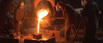
Arc or induction electric furnaces are used as melting equipment in foundries. The type of equipment is determined by the metals the foundry/site is working with: electric arc furnaces are ideal for working with steel or cast iron, while a foundry specializing in copper is more likely to use an induction furnace. Ovens can range in size from small tabletop units to those that weigh several tons.
Modern foundries are mechanized. Almost all operations of the cycle are subject to mechanization: from the production of cores to the actual casting. Molding machines are used in the serial production of castings. Manual molding is common only in small repair industries.
The main equipment includes:
- Melting furnaces;
- Pouring ladles;
- Loading and transport equipment - loaders, cranes, conveyors, etc.
- Control and automation equipment.
An electric arc furnace operates on the principle of periodic melting. The metal is melted by introducing electrical energy into the furnace through graphite electrodes. Additional chemical energy is supplied by oxy-fuel burners. Oxygen is introduced to remove impurities and other dissolved gas. When the metal is melted, slag forms and floats to the top of the melt; the slag, which often contains undesirable impurities, is removed before discharge.
An induction furnace transfers electrical energy by induction, where a high voltage electrical source induces a low voltage, high current in a secondary coil. Induction furnaces are capable of operating with minimal loss of raw materials, but are more used in the production of castings from non-ferrous metals and alloys.
All foundry equipment is specifically designed to operate reliably at elevated temperatures. The dominant trends in the production of this technology are scale, automation, rapid finishing of castings, increased safety and efficiency.
What lubricants are used? The choice depends on the brand of material and casting method. The initial concentrate in liquid form must be water-soluble, and in solid form heat-resistant pastes are used.
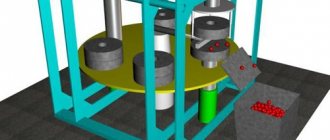
Under pressure
Injection molding technology involves the rapid supply of melt into a mold using compressor or piston mechanisms. Thanks to the automation of the process, injection molding is considered high-productivity.
In this way you can get details:
- complex geometric shape;
- with fairly thin walls;
- high precision;
- with increased roughness.
The injection molding method is used to produce parts in the automotive industry. They are light in weight and have sufficient strength, which helps reduce the total weight of the unit.
It is worth noting that the high pressure casting method has the following advantages:
- possibility of obtaining sizes of class 9 and coarser;
- achieved surface roughness - 1.25 microns;
- minimum wall size - 0.6 mm;
- minimum hole diameter - 1 mm;
- external thread formation;
- knurling, inscriptions on the outside.
The disadvantages include the following:
- the price of the forms themselves is high;
- spill of metals with low melting point;
- increased likelihood of the formation of internal defects in the form of cracks and stresses.
Die casting diagram
The widespread use of aluminum die casting is due to:
- low temperature values during the crystallization period;
- plasticity of the alloy;
- good fluidity;
- inertness to chemical reactions;
- low volume of shrinkage.
Considering ways to divide technology as follows:
- pressing chamber: hot;
- cold;
- horizontal;
- piston;
Process flow
The melt is fed into a special cavity. The piston pin forces liquid metal at high speed into the internal cavity of the mold. After which cooling occurs without removing the pressure. After hardening, the mold is released and the casting is removed. To facilitate extraction, the structure is equipped with pushers.
Technology of foundry production of ferrous and non-ferrous metals
The casting properties of materials take into account not only fluidity, but also the decrease in volume that occurs during the cooling process of the casting. This phenomenon is called shrinkage; it is 1...3% of the original dimensions. Since all metals are anisotropic, a distinction is made between linear and volumetric shrinkage, which determine the final balance of the metal. The first parameter is important for castings with an increased length to width ratio, and the second is important for castings of complex shapes.
During the cooling process of the metal, segregation is observed in its structure - heterogeneity of grains, which is caused by the different properties of the components. Impurities and non-metallic inclusions are also formed. Liquation negatively affects the properties of the final product, so they try to reduce the heterogeneity of the structure by all acceptable means. In particular, the current GOST 26645-85 “Castings from metals and alloys” limits the content of phosphorus, sulfur (as well as their compounds - sulfides and phosphides), a number of gases - hydrogen, oxygen, as well as the amount of slag not removed from the metal.
Depending on the casting properties of metals, a decision is made on the choice of appropriate technology for producing castings. There are free casting in molds (sand or metal), injection molding, squeeze casting, centrifugal casting, as well as combined methods, for example, liquid stamping.
In the chill mold
When casting into a chill mold, or into metal molds, liquid metal is poured freely, that is, under the influence of gravitational forces. The mold itself is made of two collapsible parts mounted on a plate. To obtain cavities and holes into the provided grooves into which the rods are placed. Steel and cast iron are used to make metal molds.
Chill casting process
Ventilation ducts are provided to remove gases during pouring. To prevent the melt from sticking to the internal surfaces of the chill mold, they are lined or painted with fire-resistant compounds. The thickness of the coating depends on the metal being poured and its cooling rate. Before coating, the mold cavity is cleaned and then heated to temperatures of 150 °C - 280 °C.
Features of obtaining castings:
- Due to their high thermal conductivity, alloys cool quickly in the mold, so alloys with low fluidity should have maximum wall thickness. The high cooling rate forms a fine-grained internal structure.
- The metal mold is non-yielding, so the casting is free from defects caused by permanent deformation and also prevents shrinkage. The resulting accuracy of workpieces: steels and cast irons – 7-11 classes, non-ferrous alloys – 5-9 classes.
- No burning.
- The achieved surface roughness corresponds to Rz = 40-10 µm.
- The chill mold is a gas-tight structure. Ventilation ducts and fire-resistant coatings cannot completely remove gases. In this regard, gas sinks are a common occurrence.
Advantages of chill casting:
- constant characteristics for the resulting castings;
- possibility of using sand cores;
- high performance;
- small number of operations performed;
- clean surface of finished products;
- mechanization of work;
- low qualification of workers.
Negative sides:
- significant cost of forming equipment;
- limited durability of forms;
- rapid cooling of the melt.
Almost all metals are cast into the chill mold, but the majority of castings are cast iron and cast steel.
Essence and Basics
In foundries, products are produced by melting a raw material, then pouring it into a mold, and then solidifying it. Foundries produce a wide range of products: from engine components to various containers for the food industry. All products made of cast iron, up to half of aluminum parts, up to 20% of steel products, etc. are produced by casting.
All foundry technologies are based on the concept of fluidity, when a material heated to a temperature above its melting point turns into a highly viscous liquid. In this case, the effect of continuity of its flow in the required direction must be observed. This makes it possible to form the required workpieces during the solidification process of the melt.
All casting metals have a complex structure, therefore fluidity is influenced by:
- Viscosity.
- Surface tension.
- The nature of the surface oxide film.
- Presence, content and composition of inclusions.
- Hardening method.
- Chemical composition of the base material.
- Physical and mechanical characteristics, primarily specific gravity and melting point.
Fluidity is established based on the results of chemical analyzes and technological tests in relation to a specific casting material.
If previously the process of liquid metal flow was poorly controlled, which led to various casting defects - uneven structure of the final product and porosity, now the situation has changed. In order to produce castings with optimal quality and minimize production costs, computer modeling processes have been mastered, as a result of which flow rates and the presence of various cooling effects can be predicted. They are the ones that cause porosity in the cast product.
3-D modeling allows you to adjust:
- Melt viscosity;
- Cooling intensity;
- Degree of porosity.
The spatial model of the casting developed by the technologist, taking into account the listed factors, allows even at the technology design stage to optimize the design of the part (ensuring its optimal configuration), design casting equipment, and also create the best sequence of operations performed.
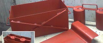
into the ground
Casting into the ground or into molds from a mixture of sand and clay is the oldest method of producing molten metal blanks. Over 80% of all castings come from it. It is distinguished by the simplicity and availability of the materials used.
The model and sprue kits are made from wood. After the model is ready, the molding mixture is mixed. The simplest ones include sand, quartz and clay.
Earth casting technology
Forming is done both manually and by machine. Manual mold making is used for the production of single or multiple castings and is considered unproductive. Machine forming is used on automated casting lines. Casting molds consist of two halves and are disposable. After pouring and cooling, the molds are destroyed. More than half of the waste material is returned to the molding operation after purification and recovery.
Defects in casting alloys
Before the casting production cycle is completed, the physical properties and structural integrity of the final product must be verified. Test methods can be destructive or non-destructive. The choice of defect detection method depends on the technological purpose of the part. Some purely aesthetic products require only a brief visual inspection to determine dimensional accuracy, presence of cracks, and quality of finish. For castings with industrial applications, all physical and mechanical properties of the metal (ductility, tensile strength, elongation, impact strength, hardness, etc.) are established during testing.
The most common casting defects are:
- Shrinkage defects. When metal hardens after being poured into molds or casting, it should shrink. When there is not enough metal, shrinkage of the cast iron will cause holes or voids to form in the casting. There are many types of shrinkage depending on its cause. With axial shrinkage, the material in the center takes longer to harden compared to the metal at the periphery, which leads to the formation of a cavity. This may be caused by the temperature at which the molten metal is poured, the speed of pouring, or the quality of the feedstock.
- Dispersive shrinkage. Dimensional changes in alloy elements can lead to a type of shrinkage where cavities form perpendicular to the casting surface. High nitrogen content or low carbon content can lead to this type of defect.
- Sometimes all foundry products may have the same type of defects in size. The reason is the different speed of solidification of different parts of the casting.
- Stitches or scars. This is a metallurgical defect, which is characterized by the presence of depressions on the surface of the casting. A defect is likely when graphite moves into shrinkage cavities during the melting process.
- Slag inclusions. They are small spots found on the surface of castings. Such inclusions are caused by contamination of the parent metal with carbides, calcites, oxides and sulfides.
- Failure to complete certain areas. Caused by the presence of gas in certain parts of the mold, reduced fluidity of the material. It will be necessary to increase its heating temperature and/or melt it in a vacuum.
Selection of specialists
This profession involves the production of cast iron, steel or non-ferrous metal parts through various casting processes, as well as periodic testing of materials to ensure quality. A specialist in a modern foundry - a cutter, a melter, a moulder - must know the various types of molds and materials, the processing of foundry tools, and the chemical processes occurring during casting.
Professional training includes:
- Theoretical vocational training;
- Internship in the company directly at the workplace;
- Internship or retraining courses.
The last stage is intended for foundry specialists who want to improve their skills. Among them may be production operators, engineers, managers, metallurgists, personnel of quality assurance departments, and labor protection specialists.
The mandatory training or retraining program includes:
- Fundamentals of metallurgical processes (materials, thermodynamics).
- Types of equipment.
- Secondary metallurgical processes (pouring, metal mixing, cooling).
- Molds, their design and maintenance.
- Casting defects.
- Modeling of foundry processes.