The hydraulic (manual) pump is quite in demand in the industrial sector. Its main task can be called pumping fuels and lubricants. At the same time, the models have their own permissible viscosity standards. Additionally, the devices differ in their design. The main element of a hand pump can be called the dispenser pipe. In some cases, telescopic intakes are used instead.
How is it built?
The standard manual (hydraulic) pump has a simple device. There is a test hose located at the bottom of the housing. It is attached to the mechanism through a special hole using clamps. There is a valve higher up in the hand pump that controls the pressure. By turning it clockwise, you can adjust the pumping force.
There is a plug for filling the tank. Below it is a small port, which is designed to connect to the general system. The mechanism also has a separate reservoir with a pipe for liquid. The hydraulic cylinder is connected to the hand pump using a threaded method. To adjust the valve intensity, manufacturers install special regulators. With their help you can easily change the pressure. In this case, the pump handle is installed separately, which is secured with a plug.
Design
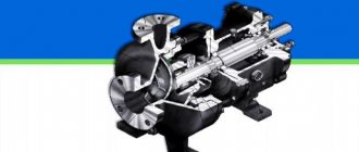
Let's look at how a hydraulic pump for a muscle-driven press is designed. A piston is installed in the cylindrical cavity of the pump housing, rigidly connected to the rod. The rod is pivotally connected to the drive lever. An intermediate valve is installed in the piston, connecting the piston and rod cavities of the pump.
The piston cavity is connected to the hydraulic tank through the inlet valve. In such pumps, the hydraulic tank is usually an integral part of their design. A suction filter is often installed in the tank in front of the inlet valve. The rod cavity is connected through the outlet valve to the outlet port of the pump. Special seals are installed in the pump housing cover, which also serves as a rod guide. A screw valve located in the bypass channel of the pump serves to return the working fluid to the hydraulic tank. A plug is provided in the housing for oil changes and maintenance.
Diagram of a hand pump for pumping out oil
To pump out large quantities of oil, a durable hydraulic cylinder is required (a diagram of a manual hydraulic pump is shown below). As a rule, it is reinforced with a small support. As a result, it is possible to secure it more tightly. Additionally, bolts are used for this.
Among other things, the hand pump is equipped with a hydraulic tube. Its main task is to supply pressure to the cylinder. For this purpose, a tee is installed in the device. It is mounted on a special cushion, which is fixed on a washer. It is also secured with nuts. A rubber band is used for the holder in the hand pump. In this case, the fitting is located at the very bottom.
What types of manual hydraulic pumps are there?
There are several design types of equipment. The simplest of all designs is a hydraulic hand pump, which is operated by hand.
We will introduce you to their features, advantages and disadvantages below:
| Hand pump designs | Features, characteristics |
| The main working body of such a pump is the diaphragm (membrane), which is why it got its name. It is movable and driven by a hydraulic drive. Although, there are both pneumatic and electromechanical options. A diaphragm pump is capable of pumping not only clean water, but also liquids with a high content of abrasive substances, so they can be used, for example, for drainage or pumping sewage.
Diaphragm pumps are classified as positive displacement mechanisms. That is, they have a chamber that forcibly changes its volume, sucking and expelling liquid. In this case, the membrane contributes to this: it makes oscillatory movements along the shaft, bending either towards the suction pipe or towards the outlet. Thus, the operating cycle of the mechanism is represented by successive stages: suction, injection, displacement.
|
| The operation of piston pumps is also based on the reciprocating movements of the working body, only in this case it is not a diaphragm, but a piston. It is driven by mechanical force and displaces water from the discharge chamber to the outlet pipe.
Uneven flow caused by cyclic suction and injection of liquid is eliminated by creating several working chambers in the pump housing. The design of a piston-type manual hydraulic pump, which has a multi-chamber design, allows for pumping in each chamber sequentially, thereby increasing the total flow.
|
| The operating principle of the rod pump is similar to the previous version. The only difference is that the piston cylinder has a considerable length and is more like a rod. The principle of its operation is to create a vacuum in the working chamber, which raises water to the surface.
|
| This pump design is initially oriented to work with a manual drive, and is intended for pumping water at low pressure. In fact, the design of a vane hand pump is an analogue of a piston mechanism, only instead of a cylinder, the working body here is a wing. Its movement occurs due to the mechanical force exerted on the handle extended outward.
|
When purchasing a manual hydraulic pump, you should take into account some indicators:
- External dimensions and weight.
- Viscosity level in the working fluid.
- Efforts on the handle.
- Pressure of stages (first and second).
- Volume of the tank.
- Cost of goods.
Advice. Before purchasing equipment, it is recommended to familiarize yourself with the operational properties and technical characteristics.
The tool is selected depending on the power supply to the entire system and the equipment as a whole to which the manually driven hydraulic pump is connected.
Pump repair
In order to repair a hydraulic hand pump, you need to find out as much as possible about the breakdown. First of all, you should look at the pressure gauge readings. If the pressure deviates from the norm, this is due to the central reservoir, the tightness of which may be compromised. In order to replace it, you will need a standard set of tools. First of all, unscrew the upper bushing and disconnect the hydraulic pump handle. Next, you need to carefully remove the protective washer.
After this, it is possible to disconnect the plug. Directly below it is a reservoir. If external inspection does not show obvious deformation, the shut-off valve must be unscrewed from it. After this, experts advise checking the functionality of the valve. If it is quite tight, you need to lubricate it. After this, the mechanism should be folded and checked for functionality.
The second common problem with pumps is considered to be abrasion of the rubber plug. In this case, you can simply replace it. In this case, it is necessary to find out its exact diameter and thickness. After completing the repair work, the entire mechanism also needs lubrication.
How are homemade models created?
Today, homemade devices of this type are quite rare. However, you can make a hydraulic pump (manual) with your own hands. First of all, a steel tank is used as a body. It requires a valve to control the pressure. It is secured at the top with a washer. A lever is used to adjust the shut-off valve. In this case, you can use a cast iron pipe. To control the pressure, a pressure gauge should be installed.
You will need a sleeve with a pipe that will prevent the valve from twisting. As a result, you can fold a device that can withstand a pressure of no more than 4 atm. A distinctive feature of homemade hand pumps is their large dimensions. And to bring the lever into operation, great efforts must be made. Considering all of the above, such devices are considered ineffective and are rarely used in industry.
Hydraulic pumps NRG
HP pumps are reliable pressure sources. Moreover, they can be connected to various hydraulic systems. The manual hydraulic pump NRG-7007 has a nominal tank volume of 0.7 liters. At the same time, its useful volume is 0.6 liters, and this modification can withstand a pressure of 1.3 MPa. Overall its performance is pretty good. If we consider high-pressure pumps, then the NRG-7110 device deserves attention.
Its nominal tank volume is 1 liter. In this case, the maximum pressure is maintained at 2.7 MPa, and the force on the handle must be applied at 50 kgf. The dimensions of this modification are as follows: width - 310 mm, height - 320 mm, and length - 750 mm. The hydraulic pump (manual) NGR-7016 has a nominal tank volume of 16 liters. At the same time, its useful volume is 14 liters. The pressure at the first stage is maintained at 2.7 MPa, and the system capacity is 113 cubic meters. see in one move. This hydraulic (manual) pump weighs as much as 29 kg.
NRG pumps with distributors
Hand pumps of the NRG series are produced in some cases with distributors. These models have the letter “P” in their names, so anyone can recognize them. A distinctive feature of these devices is considered to be high maximum pressure. Moreover, their tanks are installed in a variety of diameters. If we consider the modification NRG-7020R, then the useful volume of the chamber is exactly 2 liters, and the pressure is maintained at around 3 MPa.
The productivity of the device at the second stage is 113 cubic meters. see the move. In this case, the force on the handle should be applied at 55 kgf. This hydraulic (manual) pump weighs 22 kg. If we consider the NRG-67016R model, then its nominal tank volume is 14 liters, the “maximum” pressure is maintained at 4 MPa. The capacity of the mechanism at the second stage is 115 cubic meters. cm per move. The assembled device weighs exactly 30 kg.
Symbols of hydraulic drive elements on hydraulic diagrams
Conventional graphic symbols serve to functionally represent hydraulic drive elements and consist of one or more basic and functional symbols. In accordance with the standards DIN ISO 1219-91, GOST 2.781-96 and 2.782-96, the following basic symbols are used:
- continuous line - main hydraulic line (suction, pressure, drain), electrical line;
- dotted line - control line, drainage, indicating an intermediate position;
- dash-dotted line - combining several components into a single block;
- double line - mechanical connection (shaft, rod, lever, rod);
- circle - pump or hydraulic motor, measuring device (pressure gauge, etc.), check valve, swivel joint, hinge, roller (with a point in the center);
- semicircle - rotary hydraulic motor;
- square (with a connection perpendicular to the sides) - hydraulic device, drive unit (except for the electric motor);
- square (with connection at the corners) - air conditioner of the working environment (filter, heat exchanger, lubricator);
- rectangle - hydraulic cylinder, hydraulic device, setting element;
- a rectangle open at the top - a tank;
- oval - battery, gas cylinder, supercharged tank.
Functional symbols include triangles (black for hydraulics, white for pneumatics), various arrows, lines, springs, arcs (for throttles), and the letter M for electric motors.
Hydraulic distributor symbols
In the designation of hydraulic valves, several squares are located nearby (in accordance with the number of positions, i.e. fixed positions of the spool relative to the body), and hydraulic lines are connected to one of the positions (initial): P - pressure, T - drain, A and B - for connection hydraulic motor. The number of hydraulic lines can be different: P, T, A and B - for four-line devices; P, T and A - for three-line; P, T1 (TA), T2 (TV), A and B - for five-line, etc.
Examples of symbols for hydraulic valves
In Fig. 1.6, a shows the symbol of a four-line three-position device (4/3 hydraulic valve) with electrical control from two pushing electromagnets (Y1 and Y2) and spring return to the original position 0, in which all lines are locked. When the Y1 electromagnet is turned on, the spool moves to the right, and you can determine the option of connecting the lines by mentally moving the square corresponding to position a to the place of the square at position 0. As you can see, lines P-B and A-T are connected. When the electromagnet Y2 is turned on in position b, a connection occurs between P-A and B-T. If it is necessary to show the connection of lines in intermediate positions at the moment of switching from one position to another, dotted squares are added between the main positions (Fig. 1.6, b). In hydraulic valves controlled, for example from a proportional electromagnet Y3 (Fig. 1.6, c), many different intermediate positions are possible, and two horizontal lines are added to the symbol. Conventional graphic symbols of the main elements of the hydraulic drive are given in table. 1.1.
Conventional graphic symbols of the main elements of the hydraulic drive
Example of a hydraulic circuit
Conventional graphic symbols of the main elements of the hydraulic drive
Letter position designations of the main elements of the hydraulic circuit:
- A - Device (general designation)
- AK - Hydraulic accumulator (pneumatic accumulator)
- AT - Heat exchanger
- B - Hydraulic tank
- VD - Moisture separator
- VN - Valve
- VT - Hydraulic displacer
- G - Pneumatic silencer
- D — Hydraulic motor (pneumatic motor) rotary
- DP - Flow Divider
- DR - Hydro throttle (pneumatic throttle)
- ZM - Hydraulic lock (pneumatic lock)
- K - Hydrovalve (pneumatic valve)
- KV - Hydraulic valve (pneumatic valve) time delay
- KD - Pressure hydraulic valve (pneumatic valve)
- KO - Hydrovalve (pneumatic valve) reverse
- KP - Hydraulic valve (pneumatic valve) safety
- KR - Hydrovalve (pneumatic valve) reducing
- KM - Compressor
- M - Hydraulic motor (pneumatic motor)
- MN - Pressure gauge
- MP - Hydrodynamic transmission
- MR - Oil sprayer
- MS - Oil Can
- MF - Hydrodynamic coupling
- N - Pump
- NA - Axial piston pump
- NM - Pump-motor
- NP – Vane pump
- HP - Radial piston pump
- PG - Pneumatic-hydraulic converter
- PR - Hydraulic converter
- P - Hydraulic distributor (pneumatic distributor)
- RD - Pressure switch
- RZ - Spool valve hydraulic device (pneumatic device)
- RK - Valve hydraulic device (pneumatic device)
- RP - Flow regulator
- PC - Receiver
- C - Separator
- SP - Flow adder
- T - Thermometer
- TR - Hydrodynamic transformer
- UV - Air bleeder device
- US - Hydraulic booster
- F - Filter
- C - Hydraulic cylinder (pneumatic cylinder)
Conventional and graphic symbols are used to depict various elements and devices on hydraulic diagrams - All sizes of conventional graphic symbols specified in the standards can be changed proportionally.
In addition, you can use other graphic symbols - Graphic symbols are made with lines of the same thickness as the communication lines.
To simplify the diagram drawing (reducing kinks and intersections of communication lines), conventional graphic symbols can be depicted rotated by an angle multiple of 90 or 45 degrees, as well as mirrored - Elements and devices of hydraulic, pneumatic and thermal circuits are shown in their original positions (check valve closed, springs in a state of compression).
On diagrams it is allowed to place various technical data, the nature of which is determined by the purpose of the diagram - They can be located near the graphic (on the right or top) or on the free field of the diagram (preferably above the main inscription).
Near the graphic designations of elements, their alphanumeric designations are indicated, and in the free field of tables, diagrams, text instructions - An alphanumeric designation consists of a letter designation (BO) and a serial number placed after the BO - BO schemes are determined by GOST 2.704-76 [50] - For designations, capital letters of the alphabet are used, which are initial or characteristic of the name of the element - Letters and numbers in positional designations on the diagram are made in a font of the same size - Sequence numbers must be assigned in accordance with the sequence of arrangement of elements or devices on the diagram from top to bottom in direction from left to right.
Technical data about the elements of the circuits must be written down in the list of elements - In this case, the connection of the list with the conventional graphic designations of the elements should be carried out through positional designations - For simple circuits, it is allowed to place all information about the elements near the conventional graphic designations on the shelves of leader lines - The list of elements is drawn up in in the form of a table and placed on the first sheet of the diagram above the main inscription, the distance between them must be at least 12 mm - The list can also be made in the form of an independent document in A4 format.
The main inscription indicates the name of the product and the name of the document - The following data is indicated in the columns of the list: in the column - the position designation of an element, device or designation of a functional group on the diagram; in column - the name of the 26th element in accordance with the document on the basis of which it was applied and the designation of this document - If it is necessary to indicate the technical data of the element, it is recommended to indicate them in the column.
The diagram may indicate the parameters of flows in communication lines: pressure, flow, temperature, etc., as well as parameters to be measured at control taps.
Double acting hydraulic system
A double-acting hydraulic system requires a standard adapter as well as a pump. In this case, the coupling half is used from the BRR series. It should also be noted that the rod can be connected to the system, and this is done to return the stroke. By default, it is assumed that there is one hydraulic pipe, but several can be connected. In order to connect the pump to the actuator, a special hydraulic lock is used. It is installed on two connectors at once. In this case, the pressure can jump to 3 MPa.
In this case, you should constantly monitor the pressure gauge readings. After installing the hydraulic lock, you need to tighten all the bolts and check the rod for functionality. Additionally, it should be noted that protective bushings in this system can only be used of the UGZ class. This is due to the fact that it is necessary to connect to the actuator with exactly two connectors.
Symbols on hydraulic diagrams adopted in the USSR
The method of depicting lines in the hydraulic systems of machine tools is not standardized - The most convenient seems to be the following method, adopted by many organizations and used in the technical literature:
- highways connecting various devices - with thick solid lines;
- highways made inside the devices are thin solid lines;
- drainage lines - with thin dashed lines - Symbols of devices are drawn with contour solid lines of normal thickness - The connection points of the lines are indicated by a line and a dot (pos - 43, fig - 4); intersections without connections should be marked with a contour sign (pos. 44, fig. 4).
Figure 4 shows the main symbols on hydraulic diagrams adopted in the USSR:
Hydraulic circuit designations
- general designation of an unregulated pump without specifying the type and type;
- general designation of an adjustable pump without indicating the type and type;
- double-acting, unregulated, vane (rotary vane) pump, types G12-2, G14-2;
- twin vane (rotary vane) pumps with different capacities;
- unregulated gear pump type G11-1;
- unregulated radial piston pump;
- adjustable radial piston pump type PPR, NPM, NPChM, NPD and NPS;
- pump and hydraulic motor are axial piston (with swashplate), unregulated;
- pump and hydraulic motor axial piston (with swashplate) adjustable types 11D and 11P;
- general designation of an unregulated hydraulic motor without specifying the type;
- general designation of an adjustable hydraulic motor without indicating the type;
- plunger hydraulic cylinder;
- telescopic hydraulic cylinder;
- single-acting hydraulic cylinder;
- double-acting hydraulic cylinder;
- hydraulic cylinder with double-sided rod;
- hydraulic cylinder with differential rod;
- single-acting hydraulic cylinder with piston return with spring rod;
- servomotor (torque hydraulic cylinder);
- apparatus (main symbol);
- spool types G73-2, BG73-5 controlled by an electromagnet;
- manually controlled spool type G74-1;
- spool with controls from a cam type G74-2;
- check valve type G51-2;
- pressure spool type G54-1;
- pressure spool type G66-2 with check valve;
- two-way spool type G74-3 with check valve;
- safety valve type G52-1 with overflow valve;
- pressure reducing valve type G57-1 with regulator;
- four-way valve, type G71-21;
- four-way three-position valve type 2G71-21;
- three-way valve (three-channel);
- two-way valve (through);
- damper (unregulated resistance);
- choke (unregulated resistance) types G77-1, G77-3;
- throttle with regulator types G55-2, G55-3;
- general designation of the filter;
- plate filter;
- mesh filter;
- pressure switch;
- pneumatic hydraulic accumulator;
- pressure gauge;
- pipe connection;
- pipe intersections without connection;
- plug in the pipeline;
- reservoir (tank);
- drain;
- drainage.
How do hand pumps operate from a station?
The hand pump can only be connected to the station using an adapter of the ШП series. In this case, the standard connection diagram provides for the presence of a drain pipe. It is produced with the “T” marking. Additionally, you will need a valve that will regulate the pressure. The coupling half of the device is directly attached to the second hose. In this case, the central rod is not used. This is due to the lack of a hydraulic lock.
Ultimately, the system must be closed on the actuator. In order to check the functionality of the pump, the valve should be fully screwed in until it stops. Next, the actuator is turned on. At this time, the pressure gauge should not show pressure. If any problems occur, you should completely check the circuit for integrity.
Design of pumps with half-coupling
A feature of pumps with a half-coupling is considered to be volumetric cylinders. At the same time, they are attached to the camera using special clamps that are fixed with bolts. Additionally, there is a protective washer that locks the central rod. Directly below this is a small tee that connects to the hand pump sleeve.
For its stability, as a rule, a small pillow is used. It is attached to the body with two bolts and washers. Immediately behind it is the first air tube. In this case, the pressure regulator is further away. The second tube in many modifications is connected to a tee. In this case, a spring washer is installed on it. In this case, it gives her the ability to change position when pressing the handle. The coupling half is directly screwed to the fitting of the hand pump.
Diagram of the device from the electric petrol drive
In this case, a jack or a puller can act as an actuator. In this case, the station is attached directly to the pump. For this purpose, only rubber clamps are used, which provide high grip. The pressure gauge is installed as standard near the actuator.
The tap should be mentioned. For a hand pump to work properly, it must be a two-way pump. In this case, the air tank will withstand any load. The safety valve in this system is mounted immediately above the high pressure hose.
Example of a hydraulic circuit for a grinding machine
Example of a hydraulic circuit for a grinding machine
Features and benefits of hydraulic drive
Hydraulic drive is a set of devices (which includes one or more volumetric hydraulic motors) designed to drive mechanisms and machines using working fluid under pressure. Hydraulic drives are one of the most rapidly developing sub-sectors of modern mechanical engineering [13, 21]. Compared to other known drives (including electromechanical and pneumatic), hydraulic drives have a number of advantages. Let's look at the main ones.
- Possibility of obtaining large forces and powers with limited sizes of hydraulic motors. Thus, a hydraulic cylinder with a piston diameter of 100 mm at a pressure of 70 MPa, which can be created by a hand pump, develops a force of about 55 tons, so using special jacks you can manually lift bridges.
- High performance while ensuring the required quality of transient processes. Modern hydraulic drives, for example test benches, are capable of processing a given impact with a frequency of up to several hundred hertz.
- Wide range of stepless speed control with good smoothness of movement. For example, for hydraulic motors the control range reaches 1:7000.
- Possibility of protecting the hydraulic system from overload and precise control of acting forces. The force developed by a hydraulic cylinder is determined by the area of its piston and the operating pressure, the value of which is set by adjusting the safety valve and controlled by a pressure gauge. For a hydraulic motor, the amount of torque developed is proportional to the working volume (overall dimensions of the hydraulic motor) and the effective pressure of the working fluid.
- Obtaining linear motion using a hydraulic cylinder without kinematic transformations (an electromechanical drive usually requires a gearbox, screw or rack and pinion gear, etc.). By selecting the areas of the piston and rod chambers, it is possible to ensure a certain ratio of forward and reverse stroke speeds. An important circumstance is the ideal protection of hydraulic cylinders from external contaminants, which allows the successful operation of hydraulic drives, for example, in mining equipment, excavators and other machines operating in conditions of increased environmental pollution, and in some cases under water.
- An extensive range of control mechanisms , ranging from manual control to direct control from a personal computer, makes it possible to optimally use hydraulic drives to automate production processes in various fields of technology, successfully combining the exceptional power and dynamic qualities of hydraulics with the ever-expanding capabilities of microelectronics and complex control systems.
- The extensive possibilities for energy storage and recovery provide a good basis for the development of modern energy-efficient hydraulic drive mechanisms.
- The layout of hydraulic drives mainly from standardized products , mass-produced by specialized factories, reduces manufacturing costs, improves quality and reliability, facilitates the placement on a machine of a large number of compact hydraulic motors (hydraulic cylinders or hydraulic motors) powered by one or more pumps, opens up wide opportunities for repair and modernization.
- Avrutin Handbook on hydraulic drives of metal-cutting machines, 1965
- Biryukov B.N. Hydraulic equipment for metal-cutting machines, 1979
- Leshchenko V.A. Hydraulic servo drives of machine tools with program control, 1975
- Sveshnikov V.K Machine-tool hydraulic drives: reference book, 6th ed. reworked and additional 2015
- Smirnov Yu.A. Malfunctions of hydraulic drives of machine tools, 1980
- Kucher A.M. , Kivatitsky M.M., Pokrovsky A.A., Metal-cutting machines (Album), 1972
Bibliography:
High pressure pump
A distinctive feature of high pressure pumps is their durable hose. In this case, the valve is installed as a plunger type. It is attached to the body with two bolts. So the connection is quite rigid. There is a large lever to adjust the operation of the device. The rear cover of the hand pump is secured using a clamping rod. It, in turn, is connected to an air reservoir.
The manual hydraulic high-pressure pump “Hansa-014T” is capable of withstanding a maximum load of up to 700 bar. However, it is intended exclusively for mineral oil. It is also allowed to use distilled water. Adjusting this modification is quite simple. For this purpose, the sample is equipped with a rotary valve. Additionally, a durable hose 1 meter long should be noted.
In turn, the manual hydraulic high-pressure pump “Khansa-015T” is a more powerful prototype. It can withstand a maximum load of 800 bar.
An additional nut is provided to protect the system. The tank of this model is made of aluminum. In this case, the central rod is made of copper. It should also be noted that the entire body is made of stainless steel. In this case, the handle is rubberized and very comfortable, and this unit weighs about 25 kg when assembled.
Classification
Extensive experience in the creation and operation of various hydraulic drives has shown that only limited types of pumps can develop high pressure. These include piston and plunger types. The hydraulic pump drive comes in three design types:
- manual (muscular);
- mechanical;
- pneumatic.
The use of hydraulic drives with ultra-high pressure (over 70 MPa) makes it possible to significantly reduce the dimensions and weight of equipment and increase its specific performance. The development of high-pressure systems is one of the key factors in the creation of compact, powerful hydraulic drives and mini-equipment for various sectors of the economy.

