Review of existing options
Based on the advantages and disadvantages of all types of hand pump models, you can choose ready-made equipment in a store or make a similar design yourself.
Ready-made models
Among the ready-made options, several models are popular.
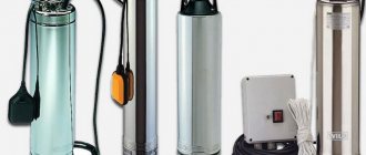
- Downhole hand pump NR-3M. This model is made of impact-resistant polymers; it also contains parts made of rubber and primed steel. For a full cycle, the device produces 1500 ml of liquid. The well depth for such a pump can be from two to five meters (in the latter case, it is necessary to install a check valve at the lower end). The weight of the device is 4600 grams, and its cost is only 2500 rubles.
- Pump design RN-01 NZh. Its body is made of stainless steel, other parts are made of brass, as well as primed and painted steel. The depth of the well can be from 6 to 9 meters. Productivity per cycle is 1000 ml. The device weighs 8 kg and costs 6,500 rubles.
- A special variety is the BSD type cast iron pump. It has an open spout design made in the form of a trough. The permissible well depth is from 6 to 9 meters. In one cycle, the pump circulates 500 ml of water. Its weight is 7 kg, and its cost is 3200 rubles.
Handicraft production: methods
There are a number of DIY techniques that will allow you to make your own hand pump. So that any of the methods can be carried out correctly, it is recommended to draw up drawings for the future design in advance. There are several methods of artisanal production.
First option
The product for pumping a well is made from a casing pipe and is used as a backup option in case of a power outage. To cut metal parts, you should use a grinder, and you will also need a drill to drill holes for fasteners. The metal part for the frame should have a cylindrical shape, for example, a part of a sediment pipe will do.
This type of work can only be performed by those who have experience in welding.
The structure, in addition to the sediment pipe, must be equipped with the following elements:
- bottom cover;
- two check valves on the pipes;
- rubber gasket;
- a piston mounted on a rod;
- round lid (for cylinder);
- a metal lever connected to the lid;
- metal connecting pins.
Second option
It is possible to create a pump using a used fire extinguisher as a pump tank. Such a device will be indispensable for cleaning a well from dirty water and can be installed at a fairly large depth - up to 15 meters.
To make the device, you also need to use a welding machine and a metal cutting tool. Using a fire extinguisher as a body and other spare parts, it is necessary to build a structure with all the elements:
- a special stand to install the pump in the ground;
- pipe (at the top of the body);
- a spout to supply water;
- collection of water;
- a handle with which to drag the structure;
- a special seal located between the body and the frame;
- the rod on which the housing is attached.
PREPARATION FOR OPI
Suction rod pumps (SRP): design, principle of operation, varieties.
Immediately before the transfer of sucker rod pumps to operation using a linear drive, for the purpose of subsequent evaluation of the technology, a set of studies was carried out, including taking a dynamogram of the pump operation using a clamp-on sensor, performing a set of measurements of liquid flow rate at the AGZU and determining the dynamic fluid level in the well using echo sounding. In addition, an analysis of the water cut of products based on wellhead samples was carried out and electricity consumption was measured using an AR.5 energy quantity and quality indicator analyzer.
Rice. 3. GMC control and monitoring system
During the tests, the operation of the installation was controlled according to the readings of the LRP control system and, to a greater extent, remotely through the GMC system (Fig. 3). For example, dynamometer testing was performed remotely to obtain wattmeterograms; the loads on the polished rod, the level above the pump inlet, etc. were measured.
The GMC system allows you to monitor parameters both in the form of a report at a certain point in time, and in the form of trends over time. Electricity consumption was measured instrumentally using the AR.5 device immediately after converting the well to LRP and changing the pump from НН-44 to НН-57 after geological and technical work.
Rice. 4. Installation of a USP with a LP in a well
The time spent on supervising the installation of the LRP, which included the initial assembly of components, pouring oil into the gearbox and rack and pinion mechanism, setting up and putting it into operation, amounted to only four hours (Fig. 4). A truck crane was used during installation. When changing the pump, the dismantling and re-installation of the LRP was carried out by the installation department of the production department. At the same time, a team of three people installed and launched the equipment in just 35 minutes
During this stage of work, a very important advantage of dismantling the LRP was noted: the drive can be dismantled and installed on the floor in a vertical position: in this case, there is no need to drain the oil from the rack and pinion mechanism. If the drive is installed in a horizontal position, it will be necessary to drain the oil from the rack and pinion mechanism and refill it before installing the LRP
There is no need to drain and refill the oil into the gearbox due to its complete sealing.
Electric motor installation
The performance of the rod CV drive depends on the operation of the electric motor, controlled by a special control unit. This equipment plays a special role, since emergency situations may arise when using the installation. For example, breakage of rods, breakdown of the gearbox, break of the pipeline, poor quality of the pump, self-start of the SC after a sudden interruption of the electricity supply. SK has a lifting capacity of 2-20 tons on the head of the balancer.
Squirrel-cage asynchronous electric motors are used as a source of electricity to operate the pumping unit. 3-phase models of the AO series are characterized by the property of moisture and frost resistance. This also applies to modifications of electric motors AO2 and AOP2.
The purpose of 3-phase general industrial asynchronous electric motors of the AO2-9 repair series is associated with the duration of the mains operation. These types of electric motors can transmit energy to drive various mechanisms. They power mills, fans, pumps, smoke exhausters, machine tools, crushers, etc.
AO series electric motors are indispensable in the oil and gas industry and other industries. They are produced for different climatic regions, including the tropics, the north, etc. Modifications of electric motors can be completely different.
Types of electric motors are divided according to various criteria, including power, installation method, placement, etc. Enterprises that produce electric motors modify products at the request of the client. As a result, the operating mode of the power source of standard or non-standard form can be changed.
Plug-in pump with top mechanical fastening (according to 11AX-API)
| Mounting version | Inner diameter of the pump, mm | Tubing diameter, mm | Pump marking | Anchor shoe (support) | Analogue pumps according to OST |
| upper mechanical according to 11AX-API | 27,0 | 60,3; 73,0 | 20-106-RHAM | 40116-ZUS, 40116-M-ZUS | NV1B-29 |
| 31,8 | 60,3; 73,0 | 20-125-RHAM | 40116-ZUS, 40116-M-ZUS | NV1B-32 | |
| 38,1 | 73,0 | 25-150-RHAM | 40117-ZUS | NV1B-38 | |
| 44,5 | 73,0 | 25-175-RHAM | 40117-ZUS | NV1B-44 | |
| upper mechanical in the OM support according to OST 26.16.06-86 | 27,0 | 60,3 | 20-106-RHAM | OM-60 | NV1B-29 |
| 31,8 | 60,3 | 20-125-RHAM | OM-60 | NV1B-32 | |
| 38,1 | 73,0 | 25-150-RHAM | OM-73 | NV1B-38 | |
| 44,5 | 73,0 | 25-175-RHAM | OM-73 | NV1B-44 | |
| upper special (cone to cone) | 27,0 | 73,0 | 25-106-RHAM | 32001-M | |
| 31,8 | 25-125-RHAM | 32001-M | |||
| 38,1 | 25-150-RHAM | 32002-M | |||
| 44,5 | 25-175-RHAM | 32002-M | |||
| upper cuff according to 11AX-API | 27,0 | 60,3; 73,0 | 20(25)-106-RHAC | 32521;32522 | |
| 31,8 | 60,3; 73,0 | 20(25)-125-RHAC | 32521;32522 | ||
| 38,1 | 73,0 | 25-150-RHAC | 32522 | ||
| 44,5 | 73,0 | 25-175-RHAC | 32522 | ||
| lower mechanical according to 11AX-API | 27,0 | 60,3; 73,0 | 20(25)-106-RHВM | 32756; 32757 | |
| 31,8 | 60,3; 73,0 | 20(25)-125-RHВM | 32756; 32757 | NV2B-32 | |
| 38,1 | 73,0 | 25-150-RHВM | 32757 | NV2B-38 | |
| 44,5 | 73,0 | 25-175-RHВM | 32757 | NV2B-44 | |
| 57,2 | 88,9 | 30-225-RHBM | 32758 | NV2B-57 | |
| lower cuff according to 11AX-API | 27,0 | 60,3 | 20-106-RHВC | 32521 | |
| 31,8 | 60,3 | 20-125-RHВC | 32521 | ||
| 38,1 | 73,0 | 25-150-RHВC | 32522 | ||
| 44,5 | 73,0 | 25-175-RHВC | 32522 | ||
| upper mechanical according to 11AX-API, installed in the lower part of the pump | 38,144,5 | 73,0/60,3 | 25/20-150-RHM-T25/20-175-RHM-T | 40116-MT-ZUS | |
| lower mechanical according to OST 26.16.06-86 | 44,0 | 73,0 | 25-175-RHTM | OM-73 |
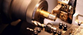
What technologies are used in metal processing
Rod borehole pumping unit
Purpose of laser machines, where they are used and why they are needed
A rod borehole pumping unit (SHPU) receives energy through a string of rods that performs a reciprocating motion caused by the operation of the pumping machine. Electric submersible centrifugal and screw pumps are driven by electric current, which is supplied through a cable from the surface. Energy can be transferred through periodic compression of the liquid, as occurs when operating wells with hydraulic piston pumps.
Rod pumping units are widely used for extracting oil from wells due to their simplicity and efficiency. Suffice it to say that over 70% of the existing well stock are equipped with self-propelled pumping units, and there is a tendency to increase their absolute number. This places great demands on the reliability of the equipment.
The block diagram of a sucker rod pumping unit (SHPU) is shown in Fig. 1.14. The installation consists of a drive, sucker rods, a deep-well pump, auxiliary underground equipment, and tubing.
| Pump screw. |
The disadvantage of rod well pumping units (SSPU) and submersible centrifugal electric pump units (ECP) is the difficulty of maintenance, instability in operation when extracting liquids with a high content of mechanical impurities and gas, as well as a low degree of reliability when working in cluster wells.
Electric motors of sucker rod pumping units are equipped with protection against multiphase short circuits, overcurrent overloads and minimum voltage protection.
In hydraulically driven rod borehole pumping units (SHPU), seals operate with movement speeds reaching 2 m/s in the presence of significant inertial loads caused by the mass of liquid, rod strings and pipes, and the pressure in the hydraulic system is 16 - 20 MPa.
A properly designed downhole sucker rod pumping unit should be capable of lifting the required amount of fluid from a given depth.
Replacing the mechanical drive of sucker rod pumping units with a hydraulic drive allows for a sharp increase in the stroke length of the rod pump, improves the characteristics of the law of motion of the rod suspension unit and reduces the metal consumption and weight of the drive part of the sucker rod pump.
One of the main disadvantages of a sucker rod pumping unit is the cyclic nature of its operation with a short cycle period and large load asymmetry at a high upper limit. All elements of the installation are subjected to cyclic action - from the engine to the intake valve of the deep-well pump.
One of the main disadvantages of a sucker rod pumping unit is the cyclic nature of its operation with a short cycle period and large load asymmetry at a high upper limit. All elements of the installation from the engine to the inlet valve of the deep-well pump are subject to cyclic influences. The intensity of accumulation of fatigue phenomena in the elements of the rod installation is 7,200 - 21,600 cycles per day.
Laboratory experiments for the model of a sucker rod pumping unit were also carried out by researchers at the Ufa Petroleum Institute, who also confirmed the presence of a spiral-shaped bend in the bottom of the tubing string during the upward stroke. The reasons for the breakdown of the plunger cells due to loading by a bending moment due to loss of stability of the tubing pipes above the pump were explained experimentally. It was shown that the cause of wire breakage when lowering instruments into the annulus is its entanglement in the coils of the tubing spiral in the lower part of the hanger.
In difficult operating conditions, the operating efficiency of sucker rod pumping units, which are equipped with over 70% of the total well stock and almost 100% of the low-yield well stock, is low and does not ensure profitability.
An adjustable energy-saving drive complex for sucker rod pumping units has been developed, which makes it possible to regulate the pump supply according to the conditions of the well's production capabilities.
The parameters found above allow us to calculate the operating parameters of a sucker rod pumping unit.
DRIVES OF DOWNLOAD ROD PUMPS
A downhole rod pump is (Figure 11) a piston type pump 1, the rod of which is a long string of rods 2, moving in a string of tubing (tubing) 3. The pump cylinder 4 is suspended from the tubing, and the plunger 1 is suspended from the rods.
Since piston pumps operate with reciprocating rods, therefore, the rod string must be imparted with reciprocating motion. For this purpose, drives for downhole rod pumps (SSP), called pumping units (SK), have been created and are used everywhere.
At each well in which a pumping pump is operated, an SS is installed, i.e. in this case, the drive is separate for each well and is called individual.
Previously, group drives were used in the fields of Azerbaijan (Figure 12). Their purpose is to impart reciprocating motion, not to one, but to a whole group of sucker rod pumps (up to 24).
The drive consists of an electric motor 1, a belt drive 2, bevel gears 3 and 4, an eccentric 5 and a yoke 6. The rods 7 of the SShN drive are attached to the yoke. The eccentric 5 and the yoke 6 are in contact with each other, therefore, when the eccentric rotates, the yoke makes a reciprocating movement, causing the rods to move.
Group drives could be used where wells are located close to each other, have a shallow depth, and the characteristics of each well can be taken into account.
At the same time, the fishing area is blocked by moving rods, difficulties are created for the movement of vehicles and people, and dangerous working conditions are created. The efficiency of the group drive is very low. Group drives were used in the fields of Bashkiria - in Ishimbay (1936-1940).
1-pump; 2-column rods; 3-column tubing; 4-cylinder pump
Figure 11 - Scheme of a deep-well pumping installation
1-electric motor; 2-belt drive; 3,4 - bevel gears; 5-eccentric; 6-yoke; 7-traction
Source
Types of wellhead equipment
A wellhead rod, which is a special rod, is necessary to connect the rod column to the rope suspension. It has a polished surface and is produced without heads with the type of thread provided by the standard. To protect the polished rod from corrosion, painting, galvanizing, and inhibition are carried out. The functions performed by the PS wellhead equipment are as follows:
- ensuring sealing of the annulus;
- well production withdrawal;
- tubing suspension.
The pumping unit is equipped with wellhead equipment, including:
- Wellhead seal. Provides sealing of the outlet of the wellhead rod due to the stuffing box head.
- Tee. It is screwed into the tubing coupling; it is necessary for the removal of well products.
- Cross. Allows you to hang the tubing string on a cone in order to correctly position it relative to the well axis.
- Shut-off valves and check valves.
A ball joint is provided for self-installation of the stuffing box head. This is ensured in case of misalignment of the stuffing box rod and tubing, whose axes do not coincide
This is important to prevent wear of the sealing packing and to make it easier to change the special packing. The presence of a cross allows the instruments to be lowered into the annulus through a wellhead pipe with a valve
Complete set of pumping machine
Among the components of the pumping machine the following stand out:
- Frame.
- A stand in the form of a truncated 4-sided pyramid;
- Balancer equipped with a rotating head.
- Traverse with connecting rods.
- Gearbox.
The SK package includes a set of pulleys that allow you to change the number of swings by discrete regulation. Changing and tensioning engine belts occurs quite quickly using a rotating frame-slide. The pumping machine is installed on a frame mounted on a reinforced concrete foundation. To fix the pump balancer, a pulley is used, which is called a brake drum. The head ensures the passage of the pumping unit during the process of repairing a well underground.
The movement of the balancer head in an arc involves its connection with the rods and the wellhead rod due to a flexible rope suspension that regulates the fit of the pump plunger into the CH cylinder. The amplitude of movement of the head of the balancer is adjusted by changing the area of the articulation of the crank with the connecting rod relative to the axis of rotation. Moving weights onto the balancer balances the action of the pumping machine. The process is considered as a balancing, rotary or combined rod balancing.
Rod deep-well pumps: design, principle of operation, varieties
Rod deep hydraulic equipment is used to service very deep wells.
An example of an industry in which the use of such hydraulic equipment is quite widespread is the oil production industry. Rod pumps are often used for pumping out oil.
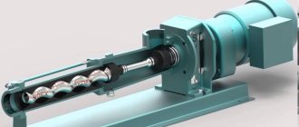
Design and principle of operation of sucker rod pumps
- A special cylindrical body, inside of which there is a plunger.
- Special discharge valve.
- Suction valve.
- Sucker rods connected to each other by a special device.
The operating principle of sucker rod pumps is very simple. With the help of a plunger, which creates a certain vacuum pressure, liquid is sucked in.
As this device begins to move downwards, liquid begins to enter the system using lifting pipes. If deep equipment operates non-stop, the liquid fills all the lifting pipes and only then enters the system on the surface.
Types of deep-rod equipment
The design allows submersible pumping equipment of this type to be divided into several types:
- Inserted rod pumps. Such pumps are immersed in the source shaft and removed from it only in assembled form. Such equipment serves deep wells with a very small flow rate of pumped liquid. Carrying out repair work on rod pumps of this type does not cause difficulties, which also acts as their advantage. Inserted rod pumps can also be divided into 2 types depending on the location of the lock: below or above.
- Non-insertable rod pumps. Installation of this pumping equipment requires complex steps. Immersion and removal of a non-insert rod pump is carried out in 2 stages. Such equipment is also divided into several types:
- pumping unit without a special catcher;
- non-insert deep well pump with gripping rod;
- non-insert deep well pump with catcher.
In addition to differences in design, sucker rod pumps can have very large differences in size, due to the specific application of the device and the requirements for it.
It is also possible to manufacture sucker rod pumps to special order, which makes it possible to create a device that provides the ability to work in special conditions.
- Non-insert pumping equipment with a catcher is very popular due to the fact that it has a simple design and a high level of reliability during use.
- The choice of sucker rod pumping equipment is influenced by specific application conditions and fluid characteristics.
- The rod pump category and technical characteristics are indicated in the form of special markings on the product, which reflect all the main characteristics and parameters of the device.
Construction details
The level of efficiency and degree of operability during the use of deep-well pumping equipment depend on various special devices.
During the operation of deep hydraulic equipment, rods experience very strong loads, which dictates special requirements for their production.
They must be made of high quality steel followed by normalization annealing. HDTV hardening is also performed. The category of pumping rod equipment depends on the type of plunger and cylinder installed and the location of the anchor shoe.
Pros and cons of sucker rod pumps
Compared to other types of various pumping equipment, rod pumps have certain advantages and disadvantages.
Advantages:
- High efficiency.
- Ease of maintenance and repair work.
- You can use different types of motors for operation.
- Can be used for servicing sand-producing sources, pumping oil with gas components.
Flaws:
- Inability to use in wells of varying depths. The risk of rod breakage increases depending on the depth of the well.
- Low flow level provided by these pumps.
- It cannot be used for servicing various wells with a large slope and a high degree of curvature.
- Cannot be used to service horizontal sources.
The choice of suitable deep-rod hydraulic equipment depends on many factors and parameters, which largely influence the efficiency and durability of its use.
How to read labels
In order to determine which category a deep-well sucker rod pump belongs to, as well as to find out what characteristics such a device has, it is enough to decipher its markings. This marking, which is not very difficult to decipher, looks like this:
The letters and numbers present in such markings consistently indicate the following parameters:
- type of sucker rod pump, which, as mentioned above, can belong to one of the following categories: HB1, HB2, NN, HH1, HH2;
- type of design of the cylinder and design features of the device as a whole;
- nominal diameter of the plunger, measured in mm (modern models of sucker-rod deep-well pumps according to this parameter can belong to devices of the following categories: 29, 32, 38, 44, 57, 70, 95 and 102 mm);
- the maximum stroke that the plunger can make (in order to find out how far in mm the plunger moves, the value in the marking must be divided by one hundred);
- head in m of water Art., which is capable of providing the presented deep-well pump (this value in the marking must also be divided by one hundred);
- landing group (according to the degree of increase in the distance between the plunger and the inner walls of the cylinder, the devices in question can correspond to one of the following landing groups: 0, 1, 2, 3).
Groups of pump landings depending on the size of the gap between the cylinder and the plunger
LAYOUT OF SCP-SCP WITH HOLLOW RODS
In 2012, as part of the System of New Technologies, we tested two different configurations of this type in the wells of OJSC Udmurtneft (together with LLC PKTB Tekhproekt) and LLC ELKAM (Fig. 5).
Rice. 5. Layout of SRP-SRP with hollow rods
In these configurations, a double sucker rod pump consists of upper and lower pumps connected in series. The lower pump takes fluid from the formation located under the packer and delivers it to the surface through hollow rods, after which the fluid passes through a tee, valve, flexible hose, flow meter, check valve into a tee that combines two streams of formation fluid. The upper pump takes fluid from the formation located above the packer and delivers it to the surface through the cavity between the hollow rod strings and tubing-73. The packer is designed to isolate oil layers during production. Also, these arrangements are equipped with heating cable lines (GCL), designed to heat the tubing in order to prevent the formation of paraffin, and can be additionally equipped with capillary tubes for supplying chemical reagents.
Advantages and disadvantages of chain drive
Model PC-80x6.1 in our country is produced by Izhneftemash JSC. Domestic equipment was created based on the development of the American company Weatherford called Rotaflex. The drive structure is equipped with a frame, which is placed on a separate base. During the equipment assembly process, the following parts are installed on the frame:
- electric motor;
- gearbox;
- belt drive;
- driving and driven sprockets;
- carriages with counterweight;
- rod columns
To connect the elements, flexible links of a continuous type are used. In the oil industry, not only balancer drives, which are considered traditional, are widely used, but also non-balancer drives, i.e. chain drives. The advantages of a chain drive for a downhole sucker rod pump can be as follows:
- The dimensions of unbalanced drives and their weight depend less on the stroke length than the parameters of these elements of a balancing-type pumping machine.
- The speed of movement of the chain drive rods is 1.6-1.7 times less in part of the stroke than the column lifting speed parameter per cycle for balancing-type pumping machines.
- Equipment productivity increases, and energy costs for lifting well product are reduced.
- The power utilization factor (PUF) increases because the electric motor load on the rod pump drive is uniform.
The load of various types placed on the rods is reduced under conditions of quiet pumping of well fluid over a long stroke. The listed advantages make it possible to harmonize the following types of indicators characterizing the operation of the equipment:
- pumping out a composition with a high degree of viscosity;
- the number of accidents that occurred with the rods;
- wear of pipes, including rods;
- well pump filling factor;
- the service life of the wellhead seal and its performance.
Despite all the reliability of the device, the balance drive has the following disadvantages:
Short life of the gearbox. Destruction of parts included in the transforming mechanism. Complicated rearrangement of connecting rod pins. High level of labor intensity in the movement of goods when achieving their equilibrium. Mass imbalance. The importance of arranging a foundation for installation, which has a high cost.
Modifications of Russian-made pumps differ in connection parameters.
Terms of use of ShSN
Manufactured types of downhole sucker rod pumps lift liquid. The state standard provides for the division of tubing columns according to the fastening method into 2 types:
- Plug-in (NSV).
- Non-insertable (NSN).
A pipe pump or pump, having a VC (suction valve) seat, is equipped with a cylinder, which is lowered into the well on the tubing. The plunger, which contains valves, must be lowered into the well before the suction, and then enters the cylinder. This is done through rods. To ensure the connection of the installation plungers with the balls of suction-type valves, special rods are used.
The disadvantage of the NSN is not only the complexity of the assembly process, but also the long time it takes to lift the device to the surface. Eliminating structural faults is difficult. Insert pumps are assembled on the surface, and then they are lowered underground on rods inside the tubing columns to a certain depth of the well.
A pipe well pump requires that when lifting the pump cylinder of the installation from underground, it must be removed entirely. This condition is considered the main distinguishing feature of NSN from NSV. Insert pumps increase the speed of hoisting operations by 2-2.5 times, which facilitates the work of workers carrying out well repairs.
An insert pump has a lower flow rate than a non-insert pump. This is due to the presence of pipes of a given diameter. The descent of the NSV is carried out on rods, and the strengthening or compaction of the element, if there are landings, is carried out on the locking support of the cylinder. It should descend onto the tubing.
The lifting of the pump from the oil well using the NSV should be carried out simultaneously with the removal of the rod string at a significant depth of descent. Operation of the NSV is carried out if the well has a low flow rate. The movement of the NSN plunger is vertical, since the descent and ascent are carried out through the rods.
Structure of the full designation of the main pump according to the API
| Nominal tubing diameter 15-1.9″ (48.3 mm) 20-2 3/8″ (60.3 mm) 25-2 7/8″ (73.0 mm) 30-3 1/2″ (88. 9 mm)40-4 1/2″ (114.3 mm) Int. pump diameter (nominal size)106-1 1/16″ (27.0 mm)125-1 1/4″ (31.8 mm)150-1 1/2″ (38.1 mm)175-1 3/ 4″ (44.5 mm)225-2 1/4″ (57.2 mm)275-2 3/4″ (69.9 mm)375-3 3/4″ (95.25 mm) | Total length of extension cords, feet Nominal Plunger Length, Feet Cylinder length, in feet Fastening type: M mechanical C lip Lock location: A upper B lower T lower, with a movable cylinder Cylinder type: W thin-walled H thick-walled Pump type: R insert T tube |
Special versions of suction valves for pipe pumps
| Non-removable valve with a built-in aeration-type drain device (TNM-S pumps). The suction valve is enlarged. There is no fishing device. | Special (cone) with a bayonet-type fishing device (TNM-K pumps). | Non-removable valve (TNM-T pumps). The suction valve (seat-ball) of pumps Zh32, 44, 57 is enlarged compared to the standard version. There is no fishing device. The pump is used in conjunction with a drain valve (such as SKOK or another design). |
| See also: Insertable deep-rod sucker rod pumps GShN Spare parts for deep-well sucker rod pumps GShN Conformity table for GShN deep-well sucker rod pumps according to API and OST standards GShN service center GShN training class |
CONCLUSIONS AND RECOMMENDATIONS
The main advantage of the technology is the unique mobility of the drug, which has been confirmed in practical conditions. The intelligent algorithm of the control station controller, based on the analysis of wattmetergrams, has demonstrated the ability to maintain the maximum pump flow within the technical characteristics of underground and surface equipment. The ability of the control station to transmit not only current information, but also the history of events in real time made it possible to optimize the process of injecting a chemical reagent to break the emulsion. The need to conduct a well study using a dynamograph and echo sounder has completely disappeared. An important advantage is that almost all moving mechanisms of LRP are closed, which increases the level of safety when operating this equipment.
However, disadvantages of the drug were also discovered. The main one, and quite serious, was the short stroke length of the drive, due to which it was necessary to switch to modes with an increased number of swings or use a plunger with an increased diameter. Such operating modes of SRP significantly increase the fatigue loads on the rods, which increases the likelihood of their breakage and reduces the service life. In turn, an increase in the number of double strokes of the rod during the operation of inclined wells would lead to increased wear of rods and tubing and, accordingly, to an increase in the frequency of equipment failures. As the LRP test example described above showed, an increase in the number of double strokes of the rod complicates the operation of wells complicated by the formation of emulsions. It should be noted that the designers of the manufacturing company UNICO are well aware of the problems associated with the design shortcomings of LRP, and based on the results of the experimental testing, they began to develop a drive with a longer stroke length, which should make this equipment more competitive.
Of course, based on the results of the operation of one installation for six months, it would be wrong to draw a conclusion about the need for widespread replication of the technology. But based on the fact that during this time it was possible to achieve all the set goals and evaluate the undeniable advantages of LRP at a real field, as well as taking into account the successful experience of operating pipelines abroad (which the company’s specialists had the opportunity to verify), the feasibility of replicating this technology is obvious. Perhaps at the first stage in a limited volume.
The scope of application for this equipment could be wells with unstable or decreasing inflow (after geological and technical measures), wells in trial operation, for which it is necessary to assess the feasibility of development; deposits in remote areas where cargo delivery is difficult (LRP weight – 1.7 tons); low-yield wells complicated by solid impurities; wells of frequently repaired stock.
The testing process was carried out under the constant supervision of representatives of the manufacturer and supplier. It became obvious that this equipment needs the control of highly qualified personnel, for the most part this concerns the settings of the control station. The overwhelming majority of manipulations with the installation were carried out by company representatives remotely from other regions and even states at any time of the day.
INSTALLATIONS OF SCREW ROD PUMPS FOR OIL PRODUCTION
Another type of sucker rod pumping units for oil production are screw rod pumping units (SSPU) with a surface drive. Their history begins in the 50s of the 20th century from the installations of screw artesian pumps of the VAN type produced in the USSR for pumping water from shallow (up to 100 m) wells with a drive through a transmission shaft assembled from rods, rotating in radial rubber-metal supports inside the pressure pipeline.
VSNU for selecting formation fluids from deep oil wells appeared on the oilfield market in the early 80s in the USA and France. Currently, a large number of standard sizes of VShNU have been created with a flow range from 0.5 to 1000 m3/day and pressure from 6 to 30 MPa.
The reason for the fairly widespread use of VPU is their technical and economic advantages compared to other mechanized methods of oil production:
compared to SSHNU.
• simplicity of design and low weight of the drive;
• no need to build foundations for the installation drive;
• ease of transportation, installation and maintenance;
• a wide range of physical and chemical properties of pumped formation fluids (the ability to pump high-viscosity fluids and high gas content);
• balanced drive, constant loads acting on the rods, uniform fluid flow, reduced energy consumption and power of the drive motor, minimal emulsifying effect on the pumped liquid;
• lack of valves in the well pump;
compared to UEVN:
• simplicity of pump design (no swivel joints, starting couplings, radial or axial bearings);
• ground location of the drive electric motor, which leads to a reduction in its cost and the absence of expensive hydraulic protection and long armored cables.
The rational area of application of VSHNU are
vertical wells or wells with low rates of curvature development with high-viscosity formation fluids with a high content of gas and mechanical impurities. Most often, VShPU are used for flow rates from 3 to 50-100 m3/day with a head of up to 1000-1500 m, however, as already noted, some standard sizes of VShPU can have much greater production capabilities.
COMPOSITION OF THE INSTALLATION AND ITS FEATURES
VSHNU (Fig. 7.128) will include surface and downhole equipment.
The surface equipment of the VSHNU is installed on the well tubing head and is designed to convert the energy of the drive motor into the mechanical energy of the rotating rod string.
Ground equipment consists of:
— tee for draining formation fluid;
— drive head;
— frames for mounting the drive motor;
— transmissions;
— drive motor with control device;
— devices for clamping (suspension) of a polished rod. Drive head
designed to transmit torque
moment of the rod string, perception of axial loads from the weight of the rods and hydraulic force in the working parts of the pump, sealing the wellhead. Structurally, the drive head is made on the basis of a housing mounted on a tee-outlet via a flange or threaded connection. Inside the housing filled with oil, on rolling bearings, there is a drive shaft connected to the driven pulley of the power transmission. Tapered or spherical roller bearings are used as a thrust bearing that absorbs axial load. To seal a rotating drive shaft or polished rod, a single or dual packing device using O-rings or soft packing is used.
Rice. 7.128. Installation of a screw rod pump
1 - drive head; 2 —
drive head;
3
- preventer;
4 -
pipe head;
5 — polished rod; 6 —
rod;
7 -
centralizer;
8 -
rotor;
9 —
stator,
10 —
finger; 11 - electric motor
To prevent reverse rotation of the rod string after stopping the drive motor, the drive head is equipped with a mechanical or hydraulic brake device. This device is necessary to perceive the torsional moment from the sucker rod string and does not allow the rod threads to turn away and reverse rotation of both the rod string itself and the elements of the drive head and transmission.
In some VSHNU layouts, for ease of installation maintenance, an additional oil seal or ram preventer is installed under the drive head. The first is used to replace the main seal without stopping the pump, which is especially important in winter operating conditions of the VShNU, the second is to seal the wellhead when repairing surface equipment.
In a number of VSHNU models from foreign companies, the drive head is equipped with a torque limiter.
When using a V-belt power transmission, the frame for the drive motor is equipped with a belt tensioning device.
The polished rod is clamped, as a rule, by two half-clamps, the inner cylindrical surface of which is secured to the rod using four or six bolts, and the outer profiled surface (for example, rectangular) is inserted into the drive shaft hub.
Downhole equipment VSHNU consists of a tubing string, in the lower part of which a pump stator is installed, and a rod string rotating in centralizers, the lower end of which is connected to the pump rotor.
The layout of the bottom of the tubing string, depending on the operating conditions of the well, may include the following elements: filter; gas and sand separators; dynamic anchor (anchor); centralizer or stator lantern; check and circulation valves; pump thrust pin.
A dynamic anchor, installed below the stator, fixes the tubing relative to the production string in the radial direction, while allowing their vertical movement. The inclusion of an anchor in the well equipment of the VSHNU is due to the fact that during the right (clockwise) rotation of the rod string, the reactive torque arising on the pump stator housing works to turn the threads of the stator and tubing. The anchor is made on the basis of a friction mechanism that activates the rams when a torque occurs. It is advisable to use an anchor at high torques due to the diameter of the screw or pump pressure. If there is no anchor when installing the overhead pumping unit, it is necessary to ensure the required fastening torques of the tubing threaded connections.
The thrust pin in the pump serves to correctly adjust the length of the rod string when installing a screw pump. Non-rotating rod centralizers, which serve as intermediate radial supports, can be presented in two designs:
— non-separable, placed directly on a full-size or shortened rod using special technology and factory conditions;
— collapsible, installed between the couplings of standard rods.
It is most rational to use rod centralizers, ensuring their immobility relative to the tubing string, which leads to a reduction in energy consumption and tubing wear. Centralizers are made of plastics or composite materials that can operate in various environments and temperature conditions.
Several lower rods located in close proximity to the eccentrically rotating rotor are not equipped with centralizers.
The reliability of the VSHNU operation largely depends on the accuracy of the axial fit of the rotor into the stator, determined by the unloading of the weight of the rod column using a weight indicator on the lifting unit or by the rotation of the rod column when the rotor moves in the stator. For axial adjustment of the rotor, the rod column arrangement, as well as in the SSNU, includes a rod offset with a length of 1 to 3 m. Precise fit, as in the SSNU, is ensured by gripping the polished rod (in the SSPU called polished or drive shaft) with special half-clamps anywhere on the surface.
When the VSP installation is operating, the lifted formation fluid moves in the annular gap between the tubing strings and rods and then through the side branch of the tee enters the field reservoir.
At VShNU, tubing and sucker rods with a diameter of 73 and 22 mm, respectively, are most widely used. The installations use standard polished rods with a diameter of 31 and 36 mm.
VSHNU CLASSIFICATION
In foreign and domestic practice, a large number of schemes and standard sizes of VShNU are known, which can be classified as follows:
— by drive type
There are installations with electric drive, volumetric hydraulic drive, internal combustion engine drive and gas engine drive. The most widely used are VSHNU with an asynchronous AC electric drive with a rated speed of 1000 rpm. The power of the electric motor, depending on the flow and pressure of the pump, varies from 3 to 100 kW and above;
— according to the kinematic drive diagram
There are VSHNU with one and two-stage transmission.
The simplest VSHNU scheme, excluding the power transmission, in which the engine is directly connected to the drive head shaft, is not used in practice, since it requires the use of low-speed motors, which is ineffective.
A single-stage transmission scheme can be implemented on the basis of a belt, chain or gear (cylindrical or conical, built into the support housing of the drive head, which in this case also serves as a gearbox).
The two-stage scheme (the first stage is a belt, the second stage is a gear drive) makes it possible to use high-speed drive motors with reduced weight and size parameters, as well as a reduction in the gear ratio of the first stage, which allows for wide regulation of the rotation speed of the rods by changing the belt drive pulleys.
In some cases, to simplify the transmission, it is advisable to use a gear motor as a drive motor.
The most widespread are drive schemes with a single-stage belt transmission;
— by belt drive type
There are drives with V-belts and toothed belts.
Most often, conventional multi-row V-belt drives are used in VSHNU. Some designs use serpentine and timing belts. The latter ensure the transmission of high torques without slipping, do not require pre-tensioning or periodic tightening, and are compact and highly efficient.
The gear ratio of a V-belt drive usually does not exceed 5, therefore, when using a single-stage transmission with a rated motor speed of 1000 rpm, the minimum possible rotation speed of the rods is 200 rpm, which does not always meet the operating requirements;
— according to shaft design
The drive head is available in solid and hollow shaft configurations.
The solid shaft arrangement, which does not require the use of a polished rod, is difficult to adjust the axial position of the pump rotor relative to the stator during installation of the rod string. In this regard, the drive shaft, as a rule, is made hollow, which makes it possible to pass a polished rod inside it and adjust the position of the latter in the axial direction;
— according to the location of the drive motor
There are layouts with vertical and horizontal engine axis.
The vertical layout of the engine is typical for single-stage belt transmissions, the horizontal (when the axis of the drive motor is located perpendicular to the axis of the well) is for drives with bevel gears;
— according to speed control method
drive shaft VSHNU distinguish between drives with an adjustable drive motor (electric or hydraulic) and with an adjustable transmission ratio, carried out by changing belt pulleys or introducing a mechanical variator into the kinematic diagram.
The most promising is the use of installations with a frequency-controlled AC electric drive, which provides a full range of speed control (from 0 to 100%) and the ability to maintain the optimal operating mode of the reservoir-pump-drive system under given conditions. Another function of the adjustable electric drive is smooth start and stop of the installation, which increases the reliability of its operation. The control station for an adjustable electric drive includes a monitoring and registration system, which allows you to monitor the operating mode of the drive and make the necessary control actions;
— according to the kinematic relation of the working bodies of the screw pump
There are pumps with a single-throw rotor (with a kinematic ratio of 1:2) and multi-threaded working bodies (with a kinematic ratio of 2:3; 3:4; 4:5, etc.).
The choice of kinematic ratio of the working parts of the pump is determined by the required operational parameters (diameter, flow, pressure, rotation speed) and the technological capabilities of screw pair manufacturers (see below);
— according to the stator fastening scheme
A distinction is made between pipe pumps (the stator is secured to a thread at the end of the tubing string) and plug-in pumps (the stator is lowered on rods assembled with the rotor and secured to the tubing using a special lock) screw pumps.
The areas of application and efficiency of the plug-in pump circuit, which allows replacing the working parts of the pump (if they wear out or in case of switching to a new pumping mode) without lifting the tubing string, are discussed in detail in Section 7.2.11. this book;
— according to the scheme for securing the bottom of the tubing
Regarding the casing, there are arrangements with a free and anchored bottom;
— according to the kinematic diagram of the pump
It is possible to implement two options: with a rotating internal element (screw) and with a rotating external element (clip).
The typical design with a rotating propeller is the simplest and most economical both in design and during installation and operation. It has found widespread use in foreign and domestic practice.
A scheme with a rotating cage, in which the flow of formation fluid rises through the internal channel of rotating hollow rods or pipes, is proposed to prevent the deposition of paraffin on the tubing and reduce hydraulic friction losses by creating a water ring on the walls of the hollow rods. This scheme is more complex, requires the use of hollow rods of increased diameter and a wellhead swivel to drain fluid from the well, and has not found industrial application.